Page is loading ...

MAINTENANCE MANUAL
Site Master™ S120A, S235A, S250A, S251A
Antenna and Cable Analyzers
1. INTRODUCTION
This manual provides maintenance instructions for
Site Master S120A, S235A, S250A, S251A Antenna
and Cable Analyzers. It describes the product and
provides performance verification procedures, parts
replacement procedures, and a replaceable parts list.
2. DESCRIPTION
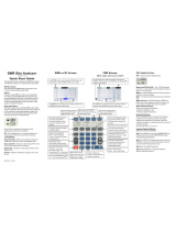
The Site Master (Figure 1) is a hand held S
21
(trans
-
mission gain or loss), SWR/RL (standing wave ra
-
tio/return loss), and Distance-To-Fault measurement
instrument. It combines a synthesized source, VSWR
Bridge, and receiver on a single printed circuit board
(PCB). An optional power monitor is also available. A
block diagram is shown in Figure 2.
3. PERFORMANCE VERIFICATION
Paragraphs 4 through 9 contain tests that can be
used to verify the performance of the Site Master
models S120A, S235A, S250A, and S251A having
any version of firmware.
3.1. Initial Setup for Testing
1. Press and hold the ESCAPE/CLEAR key,
then press the ON/OFF key to turn on
the Site Master. (This sets the instru
-
ment to the factory preset state.)
2. Release the ESCAPE/CLEAR key and use
the Up/Down Arrow key to adjust the
contrast to give a readable display.
Site Master S251A
Figure 1. Site Master S251A
490 JARVIS DRIVE ¨ MORGAN HILL, CA 95037-2809
P/N: 10580-00019
REVISION E
PRINTED: OCTOBER 2001
COPYRIGHT 1999-2001 ANRITSU CO.
Anritsu Site Master S120A Specs
Provided by www.AAAtesters.com

4. FREQUENCY ACCURACY
The following test can be used to verify the CW fre
-
quency accuracy of the Site Master. Measurement
calibration of the Site Master is not required for this
test.
a. Equipment Required:
·
Spectrum Analyzer
Anritsu Model MS2602A
b. Procedure:
1. Press and hold the ESCAPE/CLEAR key,
then press the ON/OFF key to turn on
the Site Master. (This sets the instru
-
ment to the factory preset state.)
NOTE
Before continuing, allow a five
minute warm up for the internal
circuitry to stabilize.
2.
Press the MODE soft key.
3. Use the Up/Down Arrow key to highlight
RF SOURCE, then press ENTER.
4.
Press the FREQ soft key.
5. Using the keypad or Up/Down Arrow key
enter 1000.0 MHz (S120A and S251A) or
2000.0 MHz (S235A and S250A), then
press the ENTER key.
6. Connect the RF cable from the Site Mas
-
ter Refl Test Port to the RF Input on the
MS2602A.
7. Set up the Spectrum Analyzer as follows:
(a) Press Preset.
(b) Press Center and enter 1 GHz
(S120A and S251A) or 2 GHz (S235A
and S250A).
8. If the Site Master has gone into the hold
mode, press the RUN/HOLD key to make
the measurement.
2 Site Master MM
Figure 2. Site Master Block Diagram

9. Use the Spectrum Analyzer marker to
measure the center of the response. The
frequency should be:
q
S120A: 1000 MHz ±75 kHz
q
S235A: 2000 MHz ±150 kHz
q
S250A: 2000 MHz ±150 kHz
q
S251A: 1000 MHz ±75 kHz
5. TRANSMISSION/ISOLATION
VERIFICATION
The following test can be used to verify transmission
test port isolation and the accuracy of transmission
measurements. Measurement calibration of the Site
Master is required for this test.
a. Equipment Required:
· 10 dB Attenuator, Weinshel 1R-10
· 30 dB Attenuator, Weinshel 1R-30
· Open/Short, Anritsu 22NF50
· 50 Ohm Terminations,
Anritsu SM/PL or 28N50-2
Anritsu SM/PLNF or 28NF50-2
· Armored Test Port Extension Cable,
1.5 Meter, N(m) to N(m),
Anritsu 15NN50-1.5A
b. Procedure:
1. Press and hold the ESCAPE/CLEAR key,
then press the ON/OFF key to turn on
the Site Master. (This sets the instru
-
ment to the factory preset state.)
NOTE
Before continuing, allow a five
minute warm up for the internal
circuitry to stabilize.
2.
Press the MODE soft key.
3. Use the Up/Down Arrow key to highlight
GAIN/INSERTION LOSS, then press
ENTER.
4.
Press the SCALE soft key.
5.
Press the TOP soft key.
6. On the keypad, press “0”, then press EN
-
TER. (Verify the bottom limit is set to
–120 dBm.)
7.
Press the MAIN soft key to return to the
Main Menu.
8.
Press the OPT soft key.
9.
Press the B2 soft key to turn the limit
beep ON.
10.
Press the MORE soft key, then the
MAIN soft key to return to the Main
Menu.
11.
Press the SCALE soft key.
12.
Press the LIMIT soft key.
13. Use the keypad or Up/Down Arrow key
set the limit to –85 dB (S120A) –80 dB
(S251A) or –75 dB (S235A and S250A),
then press ENTER.
14.
Press the MAIN soft key to return to the
Main Menu.
15. Press the START CAL key.
16. Follow the instructions on the display to
perform a OSL-THRU-ISOL calibration
using a 22NF50 Open/Short, 28NF50-2
or SM/PLNF Terminations, and
15NN50-1.5A Test Port Extension Cable
(refer to Figure 3).
Site Master MM 3
Figure 3. OSL-THRU-ISOL Calibration Setup

17. Connect a Load (28N50-2 or SM/PL) to
the Trans Test Port and verify that the
noise floor (isolation) is below –85 dB
(S120A) –80 dB (S251A) or –75 dB
(S235A and S250A).
18. Press the MARKER key.
19.
Press the M1 soft key, then the EDIT
soft key.
20. Using the keypad or the Up/Down Arrow
key, enter 1000.0 MHz (S120A and
S251A), or 1250 MHz (S235A) or
2000.0 MHz (S250A), then press ENTER.
21.
Press the BACK soft key, then the
MAIN soft key to return to the Main
Menu.
NOTE
For the following steps in the pro
-
cedure, use only attenuators that
have Type N connectors. The use
of attenuators with other type con-
nectors and adapters will cause
measurement errors.
22. Connect the 10 dB attenuator to the
Trans Test Port (refer to Figure 4) and
verify that the reading is:
q
S120A:10dB±2.25 dB @1000 MHz
q
S235A:10dB±2.25 dB @1250 MHz
q
S250A:10dB±2.25 dB @2000 MHz
q
S251A:10dB±2.25 dB @1000 MHz
23. Connect the 10 dB and 30 dB attenuators
in series to the Trans Test Port and
verify that the reading is:
q
S120A:40dB±3.25 dB @1000 MHz
q
S235A:40dB±3.25 dB @1250 MHz
q
S250A:40dB±3.25 dB @2000 MHz
q S251A:40dB±3.25 dB @1000 MHz
6. RETURN LOSS VERIFICATION
The following test can be used to verify the accuracy
of return loss measurements. Measurement calibra-
tion of the Site Master is required for this test.
a. Equipment Required:
· 20 dB offset, Anritsu SC5270
·
6 dB offset, Anritsu SC5237
·
Open/Short, Anritsu 22N50
·
50 Ohm Termination,
Anritsu 28N50-2 or SM/PL
b. Procedure:
1. Press and hold the ESCAPE/CLEAR key,
then press the ON/OFF key to turn on
the Site Master. (This sets the instru
-
ment to the factory preset state.)
NOTE
Before continuing, allow a five
minute warm up for the internal
circuitry to stabilize
2.
Press the MODE soft key.
4 Site Master MM
Attenuator
Figure 4. Test Setup

3. Use the Up/Down Arrow key to highlight
RETURN LOSS, then press ENTER.
4. Press the START CAL key.
5. Use the Up/Down Arrow key to highlight
OSL, then press ENTER.
6. Follow the instructions on the screen to
perform a calibration using a 22N50
Open/Short and 28N50-2 or SM/PL Ter
-
mination.
7. Connect the 20 dB offset to the Refl Test
Port and verify that the reading is:
q
S120A:20dB±1.7 dB
q
S235A:20dB±1.7 dB
q
S250A:20dB±1.7 dB
q
S251A:20dB±1.7 dB
8. Connect the 6 dB offset to the Refl Test
Port and verify that the reading is:
q S120A:6dB±1.2 dB
q S235A:6dB±1.2 dB
q S250A:6dB±1.2 dB
q S251A:6dB±1.2 dB
7. POWER MONITOR VERIFICATION
If the Power Monitor (Option 5) is installed in the
Site Master, the following test can be used to verify
the accuracy of the power measurements. Measure
-
ment calibration of the Site Master is not required
for this test.
a. Equipment Required:
·
RF Detector, 10 MHz to 20 GHz,
Anritsu 560-7N50B
·
10 dB Attenuator, Weinshel 1R-10
·
30 dB Attenuator, Weinshel 1R-30
·
RF Reference Source, 0.050 GHz,
Anritsu MA2418A
·
DC Power Supply, Anritsu 2000-933
b. Procedure
1. Connect the DC power supply to the
MA2418A Reference Source. (Refer to
Figure 5.)
2. Connect the MA2418A Reference Source
to the input of the 560-7N50B RF detec-
tor.
3. Connect the RF Detector output to the
RF Detector input of the Site Master.
4. Connect the DC power supply to the ap
-
propriate line voltage to supply power to
the MA2418A Reference Source.
5. Press and hold the ESCAPE/CLEAR key,
then press the ON/OFF key to turn on
the Site Master. (This sets the instru
-
ment to the factory preset state.)
6.
Press the MODE soft key.
7. Use the Up/Down Arrow key to highlight
POWER MONITOR, then press ENTER.
8.
Press the ZERO soft key to zero the
power monitor.
When complete, ZERO ADJ:ON is dis
-
played in the message area.
9. Verify that the power monitor reading is
0.0 dBm ±1 dB.
10. Connect the output of the MA2418A Ref
-
erence Source to the two attenuators so
as to add 40 dB of attenuation (Figure 5).
Site Master MM 5

11. Connect the MA2418AReference Source
and the attenuators to the input of the
560-7N50B RF detector.
12. Verify that the power monitor reading is
now –40.0 dBm ±2 dB.
8. BIAS T (OPTION 10) VERIFICATION
a. Equipment Required:
·
AC-DC Adapter Power Supply 40-115
·
Open/Short, Anritsu 22NF50
·
100 Ohm, 1 Watt load (100 Ohm, 1 Watt
resistor soldered from the center pin to
ground of an N-type connector.)
b. Procedure:
1. Connect the AC-DC Adapter Power Sup
-
ply to the battery charging port on the
Site Master (Option 10 only works with
the AC-DC Adapter).
2. Apply AC power to the power supply.
3. Press and hold the ESCAPE/CLEAR key,
then press the ON/OFF key to turn on
the Site Master. (This sets the instru
-
ment to the factory preset state.)
4.
Press the OPT soft key.
5.
Press the B3 soft key to activate the Bias
Tee option.
6. Verify that the display shows BIAS ON,
15.0 V, 0 mA.
7. Connect the 22NF50 short to the Trans-
mission test port.
8. Verify that the display shows BIAS ON,
Fault, and the test port voltage relay
clicks on and off.
9. Remove the short and install the 100
Ohm load.
CAUTION
The 100 Ohm resistor will get hot.
Verify the readings and remove
the 100 Ohm load immediately.
10. Verify that the display shows BIAS ON,
with a reading of 14.8 to 15.3 Volts, and
120 to 160 milliamps.
6 Site Master MM
Figure 5. Power Monitor Verification

9. TERMINATION VERIFICATION
This test verifies the accuracy of the Site Master
SM/PL termination using the precision return loss
mode of the 541XXA Scalar Measurement System.
Measurements of terminations using this mode pro
-
vide results that are traceable to the NIST (National
Institute of Standards and Technology) standards for
the precision airline.
a. Equipment Required:
·
Scalar Measurement System,
Anritsu 541XXA
·
Offset SWR Autotester,
Anritsu 560-97A50-20
·
Precision Airline, Anritsu 18N50
·
Open/Short, Anritsu 22N50
·
50 Ohm Termination, Anritsu 26N50
· Source Adapter, Anritsu 34NN50A
b. Procedure
1. Connect the test equipment as shown in
Figure 6.
2. Press the Power key on the 541XXA to
On.
3. Press the System Menu key.
4. Using the Menu up-down keys: Highlight
RESET, then press the Select key.
5. At the RESET MENU display, use the
Menu up-down keys to highlight RESET
TO FACTORY DEFAULTS, then press
the Select key.
6. Set the signal source for the frequency
range as follows:
(a) Press the Frequency key.
(b) Using the Data Entry Keypad or
Data Entry Knob, set the START
frequency to 0.01 GHz. Press the
Enter key.
(c) Using the Data Entry Keypad or
Data Entry Knob, set the STOP fre
-
quency to 4.0 GHz. Press the Enter
key.
7. Press the Channel 2 Display On/Off key to
Off.
8. Press the Channel 1 Menu key.
Site Master MM 7
541XXA Scalar Measurement System
Connect Dashed Line Connections
When Directed By Procedure
Precision
Air Line
Open/Short
Source
Adapter
50 Ohm
Termination
Offset SWR
Autotester
Termination
under Test
A
B
Beadless
End
Figure 6. 541XXA Precision Return Loss Setup

9. Using the Menu up-down keys: Highlight
PRECISION RL, then press the Select
key.
10. At the PRECISION RETURN LOSS
menu display, use the Menu up-down
keys to highlight FINAL, then press the
Select key.
11. Press the Calibration key.
12. At the CALIBRATION menu display, use
the Menu up-down keys to highlight
START CAL, then press the Select key.
13. At the PRECISION RETURN LOSS
CALIBRATION menu display prompt,
connect the Offset SWR Autotester to
Input A, if you have not done so yet.
14. Connect the precision air line to the Off
-
set SWR Autotester test port. Position
the air line pointing vertically upward.
Downward or horizontal positions make
connector pin alignment difficult.
NOTE
Ensure that the beadless end of
the precision airline is at the
measurement connection point.
15. Press the Select key when ready.
16. At the PRECISION RETURN LOSS
CALIBRATION menu prompt, connect
the Open to the beadless end of the air
-
line. Press the Select key to start the
calibration.
17. Verify that the display resembles that
shown in Figure 7.
CAUTION
During both calibration and
measurement, be sure to properly
align the beadless connector of the
airline. When the connectors are
mis-aligned, a spike will usually
be visible on the display.
18. At the next menu prompt, remove the
Open and connect the Short to the
beadless end of the airline. Press the Se
-
lect key to start the calibration process.
19. At the next menu prompt, remove the
Short and connect the 50 Ohm Termina
-
tion to the beadless end of the air line.
Press the Select key to start the calibra
-
tion process.
20. When the calibration is complete, remove
the 50 Ohm Termination.
21. Connect the SM/PL termination to the
beadless end of the air line and press the
Select key to begin the measurement.
22. Observe that the waveform displayed re-
sembles that shown in Figure 8.
23. Press the Cursor On/Off key to On.
24. Observe the CURSOR menu readout.
The minimum return loss reading for the
SM/PL termination should be 42 dB.
8 Site Master MM
10.0 dB/DIV OFFSET1: PRECSN RL (A)
2: OFF
+0.0dB
2 GHz/DIV
START: 0.0100 GHz
401 pts
STOP: 20.0000 GHz
LEVEL +7.0 dBm
54147A
PRECISION
RETURN LOSS
CALIBRATION
CONNECT OPEN
TO AIRLINE
PRESS SELECT
WHEN READY
1
Figure 7. Example of a Good Connection
10.0 dB/DIV OFFSET1: PRECSN RL (A)
2: OFF
+0.0dB
2 GHz/DIV
START: 0.0100 GHz
401 pts
STOP: 20.0000 GHz
LEVEL +7.0 dBm
54147A
CURSOR
1: -46.02 dB
PRESS SELECT
FOR
CURSOR MENU
10.0050 GHz
1
Figure 8. Direct Readout of the Precision Return Loss

10. BATTERY PACK REMOVAL
This procedure provides instructions for removing
the battery pack. Refer to Figure 9 during this proce
-
dure.
1. Place the Site Master face up on a work sur
-
face.
2. Remove the four corner rubber bumpers (1).
3. Remove the four screws (PN 900-811) (2).
4. While holding the two halves of the Site Mas
-
ter together, turn it over and set it face down
on the work surface.
CAUTION
In the next step, the Main RF PCB
assembly (3) and test port panel (4)
must stay with the front panel.
5. Remove the bottom half (5) and fold it over to
lay upside down on the work surface.
6. Disconnect the battery connector from J6 (6)
of the Main RF PCB assembly (3).
7. Remove the four screws (7) holding the bat
-
tery bracket (8) in place and lift the bracket
clear.
8. Remove the battery assembly (9).
Site Master MM 9
Te st
Ports
2 (4 places)
1 (4 places)
RF Det
Refl
Trans
CAUTION
+20 dBm MAX
40 VDC MAX
AVOID STATIC
DISCHARGE
12.5-15V DC
(850 mA)
Serial
Interface
Ext Pwr
Batt Chg
N274
Raised
Wedge
Detail A
9
7
(4 places)
6
5
8
4
3
10
Figure 9. Site Master Battery Removal

11. BATTERY PACK REPLACEMENT
This procedure provides instructions for replacing
the battery pack. Refer to Figure 9 during the proce
-
dure.
1. Install the new battery assembly (9).
2. Replace the battery bracket (8) and insert
the four screws (7) to hold the battery
bracket in place.
3. Reattach the battery connector to J6 (6) on
the main RF PCB assembly (3).
4. Set the bottom half in place.
5. While holding the two halves together, turn
the Site Master over and lay it face up on the
work surface.
6. Reinstall the four screws (2).
7. Install the rubber bumpers (1) on all four
corners of the instrument.
NOTE
Corner bumpers can only mount one
way. That is, the raised-wedged area
on the bumper inside (Detail A) at-
taches to the front cover.
12. BATTERY DISPOSAL
The battery used in the Site Master is a recharge
-
able nickel-cadmium (NiCd) battery and is covered
by the Battery Directive (91/157/EEC). As such, the
battery is marked as follows to indicate controlled
disposal.
This marking indicates that
the battery is a recyclable
product.
This marking indicates that
the battery requires separate
collection and shows the
chemical system (Nickel/
Cadmium).
This marking indicates the
heavy-metal component
concentration as a percentage
of battery cell weight.
Spent nickel-cadmium batteries are valuable re
-
sources. Because they are reusable, do not throw
them away. Arrange for proper return for recycling
in your locality. If you do not have access to proper
disposal methods, return the battery pack to your
Anritsu service center. Service centers will dispose of
the unit at no charge. Anritsu service centers are
listed in Table 2 on page 13.
13. KEY PAD MEMBRANE REPLACEMENT
This procedure provides instructions for replacing
the key pad membrane. Refer to Figure 9 during the
procedure.
1. Place the Site Master face up on a work sur
-
face.
2. Remove the four corner rubber bumpers (1).
3. Remove the four screws (PN 900-811) (2).
4. While holding the two halves of the Site
Master together, turn it over and set it face
down on the work surface.
CAUTION
In the next step, the PCB assembly
(3) and test port panel (4) must stay
with the front panel.
5. Remove the bottom half (5) and fold it over to
lay upside down on the work surface.
6. Disconnect the battery connector from J6 (6).
7. Remove the screw (10) located on the bottom
side of the main PCB assembly next to the
RF Bridge assembly.
8. Pull the PCB Assemblies clear from the top
half of the case.
9. Lift the damaged keypad membrane clear
from the keypad assembly.
10. Install a new membrane.
10 Site Master MM
Component
% of Cell
Weight
Nickel 19 to 26%
Cadmium 17 to 22%

NOTE
Carefully use pliers to pull the rub
-
ber tabs tight to ensure that the
membrane is flush with the PCB.
14. LCD REPLACEMENT
This procedure provides instructions for replacing
the Liquid Crystal Display (LCD). Refer to Figure 9
during the procedure.
1. Place the Site Master face up on a work sur
-
face.
2. Remove the four corner rubber bumpers (1).
3. Remove the four screws (PN 900-811) (2).
4. While holding the two halves of the Site Mas
-
ter together, turn it over and set it face down
on the work surface.
CAUTION
In the next step, the PCB assembly
(3) and test port panel (4) must stay
with the front panel.
5. Remove the bottom half (5) and fold it over to
lay upside down on the work surface.
6. Disconnect the battery connector from J6 (6).
7. Remove the screw (10) located on the bottom
side of the main PCB assembly next to the
RF Bridge assembly.
8. Pull the PCB Assemblies clear from the top
half of the case.
9. Remove the grey/brown cable from the con
-
nector J8.
10. Remove the four screws from the LCD PCB
assembly.
11. Carefully remove the 20-way ribbon cable
from the connector on the keypad PCB as
-
sembly.
12. Install the new LCD PCB Assembly.
15. MAIN RF PCB ASSEMBLY
REPLACEMENT
This procedure provides instructions for replacing
the main RF PCB. Refer to Figure 9 during this pro
-
cedure.
1. Place the Site Master face up on a work sur
-
face.
2. Remove the four corner rubber bumpers (1).
3. Remove the four screws (PN 900-811) (2).
4. While holding the two halves of the Site
Master together, turn it over and set it face
down on the work surface.
CAUTION
In the next step, the PCB assembly
(3) and test port panel (4) must stay
with the front panel.
5. Remove the bottom half (5) and fold it over to
lay upside down on the work surface.
6. Disconnect the battery connector from J6 (6).
7. Remove the screw (10) located on the bottom
side of the main PCB assembly next to the
RF Bridge assembly.
8. Pull the PCB Assemblies clear from the top
half of the case.
9. Remove the four screws holding the LCD as
-
sembly, but do NOT disconnect the 20-way
connector from the keypad PCB assembly.
10. While using pliers to gently squeeze the nine
plastic spacer heads to release them from the
Keypad PCB assembly, carefully pull the
keypad PCB with the LCD from the main RF
PCB assembly.
11. Remove the four standoffs and the EMI
Shield cloth.
12. Remove the three screws holding the main
RF PCB assembly to the test port panel.
Site Master MM 11

NOTE
Take care to not lose the Mylar pad
under Q5.
13. Remove the two hex standoff screws and
nuts holding the serial interface connector to
the test port panel.
14. Using a 5/16 wrench, loosen the SMA connec
-
tors for the Refl and Trans test ports and re
-
move the test port panel.
NOTE
If the Power Monitor (Option 5) is in
-
stalled, remove the two screws hold
-
ing the Power Monitor PCB assembly
to the test port panel and lift it clear
of the connector on the main RF PCB
assembly.
15. Reverse the above procedure to install the re
-
placement RF PCB assembly.
16. REPLACEABLE PARTS
Part Number Description Qty
Accessories
10580-00016
User's Guide, Site Master
S120A, S235A, S250A
1
10580-00020
User's Guide, Site Master
S251A
1
10580-00007
Battery Replacement and
Disposal Guide
1
2300-211 Software Tools, Site Master 1
40-115 Power Supply 1
SM/STS Connector, RF Short, N Male 1
SM/PL Connector, RF Termination 1
806-62 Cable Assy, Cig Plug, Female 1
800-441 Serial Interface Cable Assy 1
D41955 Carrying Case 1
Replaceable Parts
B45009-1 N-Connector, Modified 1
B45009-2 N-Connector, Modified 1
B42893 EMI Shield 1
C41761 Liquid Crystal Display Assy 1
Part Number Description Qty
ND45417 Battery Pack Kit 1
ND45292
Main PCB Assy, S120A with RF
module and cables
1
ND45296
Main PCB Assy, S235A with RF
module and cables
1
ND45353
Main PCB Assy, S250A with RF
module and cables
1
ND48761
Main PCB Assy, S251A with RF
module and cables
D41766-3 Keypad PCB Assy 1
D40864-2 Membrane Keypad, Main 1
C41767 Membrane, Soft Keys 1
Hardware
790-171 Silicon Pad 1
761-10
Cap Vinyl, Black, round, 0.625
ID
1
790-52 Washer, #4, Shoulder, Nylon 1
900-257 Pan Head Screw, 0.312 4
790-445 Spacer PCB, 0.625, Self Mount 9
900-800 Pan Head Screw, #4, 0.312 1
900-811 Pan Head Screw, #4 4
900-326 Nut, Kep, 4-40, 0.312 4
900-697 Pan Head Screw, 4-40, 0.312 3
900-138
Screw, Pan, 2-56/patchlock,
0.18
4
B41753 Gasket, LCD 1
Case Parts
D40861-3 Case 1
C40863 Bumper 4
B45018 ID, Model S120ALabel 1
B45017 ID, Model S235ALabel 1
B46687 ID, Model S250ALabel 1
48161 ID, Model S251A Label 1
12 Site Master MM

Site Master MM 13
UNITED STATES
ANRITSU COMPANY
685 Jarvis Drive
Morgan Hill, CA 95037-2809
Telephone: (408) 776-8300
1-800-ANRITSU
FAX: 408-776-1744
FRANCE
ANRITSU S.A
9 Avenue du Quebec
Zone de Courtaboeuf
91951 Les Ulis Cedex
Telephone: 016-44-66-546
FAX: 016-44-61-065
JAPAN
ANRITSU CORPORATION
1800 Onna Atsugi-shi
Kanagawa-Prf. 243 Japan
Telephone: 0462-23-1111
FAX: 0462-25-8379
ANRITSU COMPANY
10 New Maple Ave., Unit 305
Pine Brook, NJ 07058
Telephone: (201) 227-8999, 1-800-ANRITSU
FAX: 201-575-0092
GERMANY
ANRITSU GmbH
Grafenberger Allee 54-56
D-40237 Dusseldorf, Germany
Telephone: 0211-68550
FAX: 0211-685555
SINGAPORE
ANRITSU (SINGAPORE) PTE LTD.
3 Shenton Way #24-03
Shenton House
Singapore 0106
Telephone: 2265206
FAX: 2265207
ANRITSU COMPANY
1155 E. Collins Blvd
Richardson, TX 75081
Telephone: 1-800-ANRITSU
FAX: 972-671-1877
INDIA
MEERA AGENCIES (P) LTD.
A-23 Hauz Khas
New Delhi 110 016
Telephone: 011-685-3959
FAX: 011-686-6720
SOUTH AFRICA
ETECSA
12 Surrey Square Office Park
330 Surrey Avenue
Ferndale, Randburt, 2194
South Africa
Telephone: 011-27-11-787-7200
FAX: 011-27-11-787-0446
AUSTRALIA
ANRITSU PTY. LTD.
Unit 3, 170 Foster Road
Mt Waverley, VIC 3149
Australia
Telephone: 03-9558-8177
FAX: 03-9558-8255
ISRAEL
TECH-CENT, LTD.
Haarad St. No. 7, Ramat Haahayal
Tel-Aviv 69701
Telephone: (03) 64-78-563
FAX: (03) 64-78-334
SWEDEN
ANRITSU AB
Botivid Center
S-1585
Stockholm, Sweden
Telephone: (08) 534-717-00
FAX: (08) 534-717-30
BRAZIL
ANRITSU ELECTRONICA LTDA.
Praia de Botafogo, 440, Sala 2401
CEP22250-040, Rio de Janeiro, RJ, Brasil
Telephone: 021-28-69-141
FAX: 021-53-71-456
ITALY
ANRITSU Sp.A
Roma Office
Via E. Vittorini, 129
00144 Roma EUR
Telephone: (06) 50-22-666
FAX: (06) 50-22-4252
TAIWAN
ANRITSU CO., LTD.
8F, No. 96, Section 3
Chien Kuo N. Road
Taipei, Taiwan, R.O.C.
Telephone: (02) 515-6050
FAX: (02) 509-5519
CANADA
ANRITSU INSTRUMENTS LTD.
215 Stafford Road, Unit 102
Nepean, Ontario K2H 9C1
Telephone: (613) 828-4090
FAX: (613) 828-5400
KOREA
ANRITSU CORPORATION LTD.
#901 Daeo Bldg. 26-5
Yeoido Dong, Youngdeungpo
Seoul Korea 150 010
Telephone: 02-782-7156
FAX: 02-782-4590
UNITED KINGDOM
ANRITSU LTD.
200 Capability Green
Luton, Bedfordshire
LU1 3LU, England
Telephone: 015-82-41-88-53
FAX: 015-82-31-303
CHINA
ANRITSU BEIJING SERVICE CENTER
Beijing Fortune Building
416W, 5 Dong San Huan Bei Lu
Chaoyang qu, Beijing 100004, China
Telephone: 011861065909237
FAX: 011861065909236
Table 1. Anritsu Service Centers

NOTES


/