Maytag MCD2257HEB - 21.6 cu. Ft User guide
- Category
- Fridges
- Type
- User guide

MAYI:AG LAYI:A(;
® performa TM
Side by Side
....... 18-20
le Tips ..................... 21-23
Temperature Controls ................... 8-9 Care and Cleaning .................... 24-27
Fresh Food Features ................. 10-13
Operating Sounds ........................... 28
Freezer Features .............................. 14
Troubleshooting ......................... 29-32
Ice and Water ............................. 15-17
Warranty & Service ......................... 33
Form No. A/01/04 Part No. 12842103
www.maytag.com
Guide d'utilisation et d'entretien. 34
Guia de uso y cuidado ................... 70
Litho U.S.A.

ImportnntSnfetyInstructions
;;;;;;;;;;;;;;;;;;;;;;;;;;;;;;;;;;;;;;;;;;;;;;;;;;;;;;;;;;;;;;;;;;;;;;;;;;;;;;;;;;;;;;;;;;;;;;;;;;;;;;;;;;;;;;;;;;;;;;;;;;;;;;;;;;;;;;;;;;;;;;;;;;;;;;;;;;;;;;;;;;;;;;;;;;;;;;;;;;;;;;;;;;;;;;;;;;;;;;;;;;;;;;;;;;;;;;;;;;;;;;;;;;;;;;;;;;;;;;;;;;;;;;;;;;;;;;;;;;;;;;;;;;;;;;;;;;;;;;;;;;;;;;;;;;;;;;;_!!
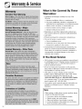
What You Need to Know About
Safety Instructions
Warning and Important Safety Instructions appearing in
this guide are not meant to cover all possible
conditions and situations that may occur. Common
sense, caution and care must be exercised when
installing, maintaining or operating appliance.
Always contact the manufacturer about problems or
conditions you do not understand.
Recognize Safety Symbols, Words,
Labels
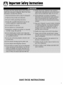
This appliance is equipped with a three-prong
grounding plug for your protection against possible
electrical shock hazards. It must be plugged into a
grounding receptacle. Where a standard two-prong
wall receptacle is encountered, it is the personal
responsibility and obligation of the customer to have it
replaced with a properly grounded three-prong wall
receptacle. Do not under any circumstances, cut or
remove the third (ground) prong from the power cord.
Do not use an adapter plug.
Power supply cord with
three-prong grounding plug
Grounding type
wall receptacle

ImportnntSnfetyInstructions
SAVE THESE INSTRUCTIONS

Installation
Location
• Do not install refrigerator near oven, radiator or other
heat source. If not possible, shield refrigerator with
cabinet material.
• Do not install where temperature falls below 55° F
(13° C) or rises above 110° F (43° C). Malfunction
may occur at this temperature.
• Refrigerator is designed for indoor household
application only.
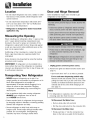
Door and Hinge Removal
Some installations require door removal to get
refrigerator to final location.
Measuring the Opening
When installing your refrigerator, allow '/2"space at top
and '/2' space behind machine compartment cover
(located in the rear) for proper air circulation. If the
refrigerator is placed with the door hinge side against
a wall, you may want to allow additional space so the
door can be opened wider.
Subflooring or floor coverings (i.e. carpet, tile, wood
floors, rugs) may make your opening smaller than
anticipated.
Some clearance may be gained by using the leveling
procedure under Leveling.
IMPORTANT: If refrigerator is to be installed into a
recess where the top of the refrigerator is completely
covered, use dimensions from floor to top of hinge cap
to verify proper clearance.
Transporting Your Refrigerator
• NEVER transport refrigerator on its side. If an
upright position is not possible, lay refrigerator on its
back. Allow refrigerator to sit upright for
approximately 30 minutes before plugging it in to
assure oil returns to the compressor. Plugging
refrigerator in immediately may cause damage to
internal parts.
• Use an appliance dolly when moving refrigerator.
ALWAYS truck refrigerator from its side or
back-NEVER from its front.
• Protect outside finish of refrigerator during transport
by wrapping cabinet in blankets or inserting padding
between the refrigerator and dolly.
• Secure refrigerator to dolly firmly with straps or
bungee cords. Thread straps through handles when
possible. Do not overtighten. Overtightening
restraints may dent or damage outside finish.
1. Unplug power cord from power source.
2. Remove toe grille and bottom bracket covers (see
page 7).
• Open both doors 180°, or as wide as possible.
For ice and water dispensing models only:
Remove the left side bracket cover by carefully
pulling the water line to pry the cover loose. Then
continue to maintain downward pressure to the
notched side of the cover while swinging it off
(see page 7).
Note
• For refrigerators in operation, shut off water before
removing water line from the door.
To Disconnect the Water Line:
• Push in white collar (A) and hold.
• Pull the door-side tube from the connector (B).
To Reconnect the Water Line:
• Firmly push tube "_8"into the connector. Use
lines on the tube as a guide for full insertion.

Installation
• If tube end is damaged, cut off %" before
reconnecting.
• If leaking occurs, reconnect the line.
3. Close doors.
4. Remove top hinge covers by
removing Phillips screws.
5. Unscrew _.;' hex head screws from
top hinges.
For water dispensing
models only:
Do ROt remove screw
connecting green ground
wire.
6. For ice and water
dispensing models only: Detach main wire
connector harness and red wire harness.
To detach main wire
harness, use a flat blade
tool or fingernail to press
junction point between two
connectors to release.
To detach red wire harness,
press tab on underside of
connector to release.
7. Remove top hinges along with
doors.
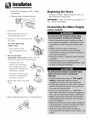
Replacing the Doors
• To replace the doors, follow the steps in Door and
Hinge Removal in reverse order.
IMPORTANT: If water line tube end is damaged, cut
off 5/8"before reconnecting.
Connecting the Water Supply
([select models)
8. Remove bottom hinges with a %" hex head driver.

Installation
Materials Needed
• '/4"outer diameter flexible copper tubing
• Shut-off valve (requires a '/4"hole to be drilled into
water supply line before valve attachment)
• Adjustable wrench
• '/_"hex nut driver
Note
• Add 8' to tubing length needed to reach water
supply for creation of service loop.
1. Create service loop with copper
tubing (minimum 2' diameter).
Avoid kinks in the copper tubing
when bending the service loop.
2. Remove plastic cap from water valve
inlet port.
3. Place brass nut (A) and
sleeve (B) on copper
tube end as illustrated.
(Do not use old sleeve.)
A
=_=* @
4. Place end of copper tubing into water
valve inlet port. Shape tubing slightly. Do
not kink - so that tubing feeds straight
into inlet port.
5. Slide brass nut over sleeve and screw nut
into inlet port. Tighten nut with wrench.
IMPORTANT: Do not overtighten. Cross
threading may occur.
.
Pull on tubing to confirm connection is
secure. Connect tubing to frame with
water tubing clamp (C) and turn on
water supply. Check for leaks and
correct if necessary. Continue to
observe the water supply connection
for two to three hours prior to moving
the refrigerator to its permanent
location.
7. Monitor water connection for 24 hours.
Correct leaks, if necessary.
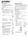
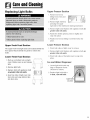
Handle Installation
If not installed, the handle is located in the interior of the
fresh food section or attached to the back of your refrig-
erator. Remove and discard handle packaging and tape.
Handle design varies from refrigerator to refrigerator.
Please reference the appropriate instructions for your
model.
Front Mount Handle with Extensions
Materials Needed
• Gloves to protect hands
• Phillips screwdriver
• Plastic door handle removal card (or '/_2"thick plastic
card), retain the card
Attach Extensions to Handle:
1.
Align handle and
extension as shown.
Place extension in
handle opening.
Apply slight pressure
to both sides of the extension piece.
Slide extension until it stops on inside edge of
handle.
To Install:
1. The handles are to be oriented
as shown.
Align front mount door handle
clip with the door tabs.
Ensure the handle clips are
positioned slightly above the
door tabs.
i
_ndle
Tab
/4. Rotate the handle so that the
handle is flat against the door.

Installation
5. Push the handle down against the upper
door tab just enough to allow it to hang
unsupported.
6. Align bottom of handle with lower door
tab. Press upper handle end to door
surface and firmly grasp lower end of
handle. Gently slide handle upward until
bottom of handle settles on door surface,
then reverse direction, sliding down-
ward to almost engaging tab with clip. ,]1';"_
7. Grasp the handle firmly and slide down
until it clicks. The audible click indicates --
fastening clips are securely interlocked.
To Remove: Ill
1. Flex the handle away from the door panel. ,
Simultaneously place door handle removal
card underneath the base of the lower
handle. Insert the card to the line or until
it stops.
2. Grasp the lower part of the handle firmly
and lift to remove.
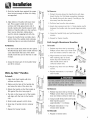
Wide-by-Side TM Handles
To Install:
1. Align fresh food handle with trim
retainer and door clip.
2. Make sure the tabs of the handle clip
are below the tabs of the door clip.
3. Rotate the handle so that the handle is
flat against the door (see page 5).
/4. The tab on the lower part of the handle
will align with the hole in the handle
cap.
5. Slide handle upward until it clicks.
6. Snap top of handle into trim retainer
clip.
7. Repeat for freezer handle.
To Remove:
.
3.
Protect the area above the handle trim with tape.
Insert the tip of a flat blade screwdriver between
the handle trim and door panel. Carefully pry the
trim away from the door panel.
Pull trim free from the trim retainer.
Insert door removal card (or '/_2"thick plastic card_}_)
between the handle and door panel (approximately
1'/_').
Grasp the handle firmly and pu[[ downward to
remove.
5. Repeat for freezer handle.
Full-Length ARurninurn HandJes
To UnstaJJ:
1. Release top door trim by removing
Phillips screws from top of fresh food
door and retain screws for later use.
Align notches on back of handle
with retaining clips on doors.
Insert clips into notches and
slide handle down until it
contacts bottom trim.
Replace top door trim and Phillips
screws.
Repeat instructions 1-3 to install
other handle.
To Remove:
1. Release top door trim by removing
Phillips screws from top of fresh food
door and retain screws for later use.
Grasp handle firmly with both hands.
Slide handle upward
approximately 3/4"to release.
Repeat instructions 1-3 to
remove other handle.
To Reinstall:
1. Repeat in reverse order.

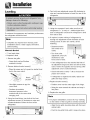
Installation
Leveling
4. Turn both rear adjustment screws (B) clockwise to
raise and counterclockwise to lower the rear of the
refrigerator.
To enhance the appearance and maintain performance
the refrigerator should be level.
Note
• Complete any required door reversal, panel
installation and/or a water supply connection,
before leveling.
Materials Needed
• 3/8"hex head driver
• Carpenter's level
1. Remove toe grille.
• Grasp firmly and pull bottom
outward to unclip.
2. Remove bottom bracket cover(s).
• Place the eraser end of a pencil or similar blunt
tool in the cover notch.
Notch
Location
• Use slight pressure to pry the
cover loose.
• Continue to maintain
downward pressure to the
notched side of the cover while
swinging it off.
3. Using hex head driver, turn both of the front
adjustment screws (A) clockwise to raise and
counterclockwise to lower the front of the
refrigerator.
Using the carpenter's level, make sure front of
refrigerator is '/4"(6 ram) or '/2bubble higher than
back of refrigerator and that the refrigerator is level
from side to side.
If required, correct rocking of refrigerator by
turning rear adjustment screw clockwise to raise
rocking corner. If doors are uneven, do the
following:
• Determine which
door needs to be
raised.
Turn front roller
adjustment screw (A)
clockwise to raise
front corner of door.
O
• If one refrigerator door has reached the limit of
its adjustment range and doors are still not level,
raise or lower the opposite door by turning roller
adjustment screw counterclockwise.
• Check with level to verify '/4"tilt to the back for
proper door closure.
• If refrigerator is aligned and stable, replace toe
grille and hinge covers.
7. Replace bracket cover(s).
• Position cover into the outer edge of the hinge.
• Swing the cover toward the cabinet and snap it
into place.
8. Replace the toe grille.
Note
• For proper reinstallation, ensure the "top" marking
on the interior of the toe grille is oriented correctly.
• Align the toe grille mounting clips with the lower
cabinet slots.
• Push the toe grille firmly until it snaps into place.

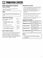
TemperatureControls
Dial Temperature Controls
Cselect models)
The controls are located at the back left of the
refrigerator compartment.
Note
• The freezer control turns the cooling system on.
Neither section will cool if freezer control is set to
OFE
Initial Control Settings
After plugging the refrigerator in,
set the controls.
• To adjust the controls, turn the
control knob to the left or right
as desired.
• Set the freezer control on 4.
• Set the refrigerator control on 4.
• Let the refrigerator run at least 8
to 12 hours before adding food.
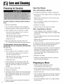
Warm Cabinet Surfaces
DuJ L"oo/
Freezer
Refride_ator /
At times, the front of the refrigerator cabinet may be
warm to the touch. This is a normal occurrence that
helps prevent moisture from condensing on the
cabinet. This condition will be more noticeable when
you first start the refrigerator, during hot weather and
after excessive or lengthy door openings.
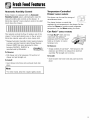
Adjusting the Controls
24 hours after adding food, you may decide that one
or both compartments should be colder or warmer. If
so, adjust the control(s) as indicated in the
Temperature Control Guide table below. See page 21
for instructions on checking compartment
temperature.
• Except when starting the refrigerator, do not change
either control more than one number at a time.
• Allow 24 hours for temperatures to stabilize.
• Changing either control will have some effect on the
temperature of the other compartment.
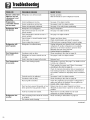
Temperature Control Guide
Refrigerator too warm Turn the refrigerator control
to next higher number.
Refrigerator too cold Turn the refrigerator control
to next lower number.
Freezer too warm Turn the freezer control to
next higher number.
Freezer too cold Turn the freezer control to
next lower number.
Turn refrigerator OFF Turn the freezer control to
OFE
Note
• Turning freezer control to OFF stops cooling in
both compartments. It does not shut off power to
the refrigerator.

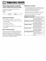
TemperatureControls
Touch Temperature Controls
Cselect models, style varies by model)
The controls are located at the top front of the
refrigerator compartment.
Control
Adjusting the Controls
24 hours after adding food, you may decide that one
or both compartments should be colder or warmer. If
so, adjust the control(s) as indicated in the
Temperature Control Guide table below.
• Except when starting the refrigerator, do not change
either control more than one number at a time.
Initial Control Settings
After plugging the refrigerator in, set the controls.
............................ads adjusts the controls to
• Pressing the _ or p
the desired setting.
• Set the freezer control on 4.
• Set the refrigerator control on 4.
• Let the refrigerator run at least 8 to 12 hours before
adding food.
Warm Cabinet Surfaces
At times, the front of the refrigerator cabinet may be
warm to the touch. This is a normal occurrence that
helps prevent moisture from condensing on the
cabinet. This condition will be more noticeable when
you first start the refrigerator, during hot weather and
after excessive or lengthy door openings.
• Allow 24 hours for temperatures to stabilize.
Temperature Control Guide
Refrigerator too warm
Refrigerator too cold
Freezer too warm
Freezer too cold
Turn refrigerator OFF
Set the refrigerator control
to next higher number by
pressing the pad.
Set the refrigerator control
to next lower number by
Set the freezer control to
next higher number by
Set the freezer control to
next lower number by
pressing the pad.
Press the freezer or
refrigerator :_ pad until a
dash "-" appears in the
display.

FreshFoodFemures
Shelves
Your refrigerator has either Spill-Catcher TM or non-
sealed shelves. Spill-Catcher TM shelves have a spill
retainer edge which allows for easier clean up and
some are equipped with the Easy-Glide slide out
feature. To slide out (select models), grasp the front of
the shelf and pull forward. Push in the shelf to return
to the original position.
To Remove a Shelf:
• Slightly tilt up the
front and lift up the
rear of the shelf, then
pull the shelf straight
out.
To Lock the Shelf Into Another Position:
• Tilt up the front edge of the shelf.
• Insert the hooks into the desired frame openings and
let the shelf settle into place.
• Be sure the shelf is securely locked at the rear.
The Crisper Top serves as the lower fresh food shelf.
To Remove the Crisper Top:
• Remove drawers as indicated (see page 12).
• Place hand under the frame to push up the glass. Lift
glass out.
To Install:
• Repeat above instructions in reverse order.
Elevator TM Shelf Cselect models)
The Elevator TM Shelf is equipped with a spill-retaining
edge and the Easy-Glide TM slide-out feature. It can be
adjusted up or down without unloading.
To Slide Out Elevator TM Shelf:
• Grasp the front of the shelf and pull forward.
• Push the shelf in to return to original position.
To Adjust the Elevator TM Shelf:
• Pull out the knob on the crank handle.
• Rotate the crank clockwise to raise the shelf, and
counterclockwise to lower the height of the shelf.
To Remove Elevator TM Shelf:
• Completely unload the shelf and pull the shelf
forward.
Pull until the shelf stops.
Press up on the tabs located underneath its outside
edges and continue pulling forward until the shelf is
clear of the frame.
To Replace Elevator TM Shelf:
• Align the shelf to the frame and push it all the way
back. It is not necessary to press up on the tabs for
reinstallation.
In ordinary use, the Elevator TM Shelf frame assembly
does NOT require removal. Though unlikely, and not
recommended, the correct removal procedure is as
follows:
To Remove Frame Assembly:
• Unload the shelf completely.
• Slide the shelf forward about 2" and manually move
the two rear latches toward the shelf center.
• While supporting the entire shelf and frame from
underneath, lift slightly and rotate the assembly
approximately 30° to allow the rear mechanism to
clear the vertical rear side rails.
• The entire assembly can then be moved forward
and clear of the refrigerator compartment.
To Reinstall Frame Assembly:
• Reverse the removal procedure. Be sure the shelf
is in a level position. When the sliding shelf is
pushed to the rear, it will reposition the rear latches
to their correct operating position.
10

FreshFoodFemures
Dairy Center
The Dairy Center provides convenient
door storage for spreadable items such
as butter and margarine. On select
models, this compartment can be
moved to several different locations to
accommodate storage needs.
To Remove:
, Slide dairy center up and pull out.
To [nstall:
, Slide assembly in and down so that the hooks are
firmly seated on the door liner.
To Remove Dairy Door:
Press in sides of dairy door and pui[ out.
To [nstaH Dairy Door:
Slide sides of dairy door inside dairy center until
hinge points snap into place.
Adjustable Deep THt-Out Door Buckets
(select modems)
The AdjustaMe Deep Timt-Out Door Bucket provides
easy access to food items stored in the door.
To Remove Bucket:
, Tilt bucket out.
,PuI[ straight out of the bracket.
To [nstall Bucket:
, Tilt the front of the bucket down slightly.
, Slide into bracket and tip upright.
To Move Bucket Frame to Another Location:
, Remove bucket.
/
, Lift bracket up and pull straight [
out.
Place the bracket in a new
location.
Door Buckets
Door Buckets can be moved to meet
individual storage needs.
To Remove:
• Lift bucket up and pull straight
out.
To Install:
• Place bucket in desired door liner retainer, push
down until bucket stops.
Storage Drawers
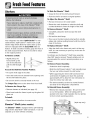
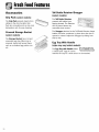
Humidity-Controlled Crisper Drawers
The Crisper Drawers provide a higher humidity
environment for fresh fruit and vegetable storage.
Controls
The crisper controls regulate the amount of humidity in
the crisper drawer. Slide control toward the Fruit
setting for produce with outer skins. Slide control
toward the Vegetables setting for leafy produce.
I
HUMIDITY CONTROLLED
11

FreshFoodFeutures
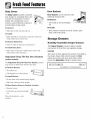
Automatic Humidity Control
Some crispers are equipped with an Automatic
Humidity Control system, eliminating the need for
manual humidity slide controls on the drawer. A
fabric-like material* covers small air vents in the shelf
insert above the crispers.
/_; _ _<__ I
i
I
This material controls the flow of moisture out of the
crisper. If a food spill should occur on the air vent or
fabric-like material, wipe with a clean, damp cloth.
* Maytag Automatic Humidity Control system features
a unique, patented material called Shape Memory
Polymer (SMP) that when laminated to fabric,
becomes DIAPLEX. DIAPLEX is
manufactured by Mitsubishi.
The Ir_teHigent _extu re
To Remove:
• Pull drawer out to full extension. Tilt up front of
drawer and pull straight out.
To Install:
• Insert drawer into frame rails and push back into
place.
i Note
• For best results, keep the crispers tightly closed.
Temperature-Controlled
Drawer (select models)
This drawer can be used for storage of
miscellaneous items.
The drawer features a control that
regulates the air temperature in the drawer. Set the
control to Cheese to provide normal refrigerator
temperature. Use the Meats setting for meats.
Can Rack TM (select models)
The Can Rack TM slides out from
underneath the Spillsaver TM
stationary shelf. The Can RackTM
holds up to twelve 12-ounce
beverage cans.
To Remove:
• Empty contents of Can RackTM. Pull forward to full
extension and lift front to release from shelf rail
assembly. Pull straight out to remove.
To install:
• Insert drawer into frame rails and push back into
place.
12

FreshFoodFeutures
Accessories
Grip Pads (select models)
The Grip Pads prevent objects from
sliding in the door buckets. Grip
Pads are removable and are top-rack
dishwasher safe for easy cleaning.
Covered Storage Bucket
(select models)
The Storage Bucket has a lid and
removable egg tray. When tray is
removed, bucket will accept items
such as a standard egg carton, ice,
etc.
Tall Bottle Retainer/Snugger
(select models)
The Tail Bottle Retainer
prevents tall bottles from
tipping forward. The Retainer
can be placed above any
removable door bucket.
The Snugger attached to the Tall Bottle Retainer keeps
bottles and other containers in place when the door is
opened or closed. Adjust the Snugger by sliding from
side to side.
Egg Tray With Handle
(style may vary/select models)
The Egg Tray with Handle holds
a "dozen-plus" eggs. It can be
removed to carry to a work area or to be washed.
13

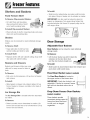
FreezerFeatures
Shelves and gaskets
Fixed Freezer Shelf
To Remove Clip-mounted Shelves:
, Lift shelf from wall mounting
clips and pull left side of shelf
out of wall mounting holes.
To Install Clip-mounted Shelves:
, Place left side of shelf in mounting holes and press
down into wall mounting clips.
Shelves
Shelves can be removed to meet individual storage
needs.
To Remove Shelf:
, Snap right side of shelf up from
cabinet railing and slide to right.
To [nstaH Shelf:
Replace shelf in left side cabinet railing. Snap shelf
into right side cabinet railing.
Baskets and Drawers
Baskets and drawers (style may vary}
slide out for easy access to items in
back.
To Remove:
, Pull out to its full extension. Lift up front of basket
and remove.
To Install:
, Slide basket or drawer into cabinet railing. Lift up
front of basket or drawer, and slide to the back of
refrigerator.
Ice Storage Bin
The [co Storage Bin is located below the automatic
ice maker.
To Remove:
, Raise ice maker arm to deactivate ice maker. Lift
front of bin and pull out to its fuil extension. Lift up
front of bin and remove.
To [nstalh
Slide bin into railing below ice maker until bin locks
into place. Drop ice maker arm to activate ice maker.
IMPORTANT: Ice bin must be locked in place for
proper ice dispensing. Turn auger driver behind bin
counterclockwise (as shown} to properly align ice bin
with auger driver.
iiiiii/
Door Storage
Adjustable Door Buckets
Door Buckets can be moved to meet individual
storage needs.
To Remove:
• Lift the door bucket up until it clears the
retainers on the door liner, then
pull the door bucket straight out.
To Install:
• Slide bucket in above desired door liner retainer and
push down until bucket stops.
Fixed Door Bucket (select models)
The Fixed Door Bucket is located in
the upper section of the freezer door.
IMPORTANT: Fixed door bucket is not
adjustable. If bucket is removed, freezer
light will not deactivate when door is
closed.
Drop-Down Freezer Door Baskets
(select models)
These baskets provide
convenient storage space for
frozen food items that tend
to shift, such as bagged
vegetables.
14

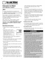
Iceu,dWuter
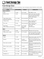
Automatic Ice Maker
Cnon-dispenser models)
Note
• Energy rating guides that are posted on the
refrigerator at the time of purchase do not include
optional ice maker energy usage.
Some models are automatic ice maker ready. The
number of the appropriate ice maker kit is IC10S. The
kit contains installation instructions and water
connection instructions.
Other models have a factory installed ice maker.
Connect the ice maker to the water supply as
instructed on page 5. Proper water flow and a level
refrigerator are essential for optimal ice maker
performance.
Operating Instructions
• Confim] ice bin is in place and ice maker arm is
down.
• After freezer section reaches
between 0° to 2° F (-18 ° to -17 ° C),
ice maker fills with water and
begins operating. You will have a
complete harvest of ice
approximately every three hours.
• Allow approximately 24 hours after installation to
receive first harvest of ice.
• Discard ice created within first 12 hours of operation
to verify system is flushed of impurities.
• Stop ice production by raising ice maker arm until
click is heard.
• Ice maker will remain in the OFF position until arm is
pushed down.
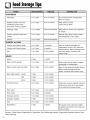
• The first one or two batches will probably contain
undersized and irregular cubes because of air in the
supply line.
• When the ice cubes are ejected it is normal for
several cubes to be joined together at the ends. They
can easily be broken apart. The ice maker will
continue to make ice until the supply of ice cubes
raises the sensor arm, shutting the ice maker off.
• Certain sounds may accompany the various cycles of
the ice maker. The motor may have a slight hum, the
cubes will rattle as they fall into an empty storage
pan and the water valve may click or "buzz"
occasionally.
If the ice is not used frequently, the ice cubes will
become cloudy, shrink, stick together and taste stale.
Empty the ice storage bin periodically and wash it in
lukewarm water. Be sure to dry the bin thoroughly
before replacing it.
Beverages and foods should not be placed in the ice
storage bin for quick chilling. These items can block
the sensor arm, causing the ice maker to
malfunction.
• Turn off (arm up) the ice maker when the water
supply is to be shut off for several hours.
To Remove the Ice Bin:
• Pull it forward, away from the ice maker. To avoid the
ice maker dumping ice while the bin is removed, turn
the ice maker off by raising the sensor arm.
To Install the Ice Bin:
• Reverse the above procedure. Turn the ice maker on
by lowering the sensor arm.
15

Iceu,dWuter
Dispenser Features
(select models)
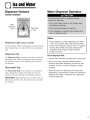
Water Dispenser Operation
Removable
/ Tray
Dispenser Light (select models)
A light activates within the dispenser area at full power
when dispensing ice or water with the main dispenser
pad.
Dispenser Pad
The Dispenser Pad is located on the back wall of the
dispensing area. When the dispenser pad is pressed,
the selection chosen on the dispenser control panel
will dispense.
RemovabRe Tray
The Removable Tray at the bottom of the dispenser
area is designed to collect small spills and may be
easily removed for cleaning and emptying purposes.
UMPORTANT: Removable tray does not drain. Do not
allow tray to overflow. If it does, remove tray and wipe
up overflow.
Note
• During initial use of water dispenser, there will be
a one- to two-minute delay while water tank fills
before water dispenses. Discard first 10-14 glasses
of water after initially connecting refrigerator to
household water supply and after extended
periods of nonuse.
To Use Dispenser Pad:
• Choose water selection from dispenser control panel.
Press sturdy, wide-mouthed container against
dispenser pad. When dispensing crushed ice, hold
container as close to chute as possible to reduce
spraying.
Release pressure on dispenser pad to stop water
dispensing. A small amount of water may continue to
dispense and collect in dispenser tray. Large spills
should be wiped dry.
16

I©eo,dWmer
17
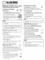
Dispenser Control (selectmodels)
(control features vary by model)
<c> c_
Ice Dispenser Operation
To Dispense Ice:
• Select Crush or Cube ice mode by pushing button
on dispenser control panel. A green light above
button indicates mode selection.
• Press container against dispenser pad
When dispensing crushed ice, hold
containerreducespraying,as close to chute as possible to
Notes
• Mode may not be changed while ice dispenser is
in operation.
• If dispenser (select models) is active for more than
five minutes, an automatic lock out sensor will
shut down power to dispenser area. See Dispenser
Lock for unlocking information.
Dispenser Lock (select models)
The Dispenser Lock prevents ice or water from
being dispensed.
To Lock Dispenser:
o
Press and hold the Lock button for three seconds. A
green indicator light above button will illuminate
when the dispenser is locked.
To Unlock Dispenser:
Hold the Lock button for three seconds. The green
indicator light above button will go out.
Water FHter Status indicator
O Water fltl_'r
Light (select models) : _o_o
The Water Filter Status Indicator Light serves as a
reminder to replace the water filter. A green light
indicates that the filter is in good condition. A red light
indicates the filter should be changed. Once light turns
red, it will remain red until function is reset.
To Reset Undicator:
Press and hold both the Lock and Water
buttons simultaneously for four seconds. The
green filter status indicator light will flash
three times when the function has
successfully reset.
o
o
Auto Light (select models) °
The Auto Light function activates the
dispenser light at half-power when the Light
Sensor detects that the light levels in room are low.
To Activate Auto Light:
• Press Auto Light button. A green indicator light
above button illuminates when the sensor is active.
To Deactivate Auto Light:
• Press Auto Light button. The green indicator light
will go out.
Note
• The dispenser light will operate when Auto Light is
ON or OFF.
Sabbath Mode (select models)
When activated, the Sabbath Mode deactivates the
control lights while leaving the control operational.
To Activate Sabbath Mode:
o
• Press and hold the Lock and Auto Light
buttons simultaneously for three to four k._
seconds. After three to four seconds, the o
dispenser lights will turn off.
To Deactivate Sabbath Mode:
Press and hold both the Lock and Auto Light
buttons simultaneously for three to four seconds.
After three to four seconds, the dispenser lights will
activate.
Notes
• Dispenser light will not activate during dispensing
while in this mode.
• If the power fails, the control will remain in
Sabbath Mode when power returns.

WaterFilter
Water Filter Removal and
Installation ([select models)
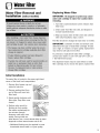
Replacing Water Filter
IMPORTANT: Air trapped in system may cause
water and cartridge to eject. Use caution when
removing.
1. Turn filter counterclockwise until it releases from
filter head.
2. Drain water from filter into sink, and dispose in
normal household trash.
3. Wipe up excess water in filter cover and continue
with Initial Installation, steps 2 and 4.
The filter should be changed at least every 12 months.
IMPORTANT: Condition of water and amount used
determines life span of water filter cartridge. If water
use is high, or if water is of poor quality, replacement
may need to take place more often.
To purchase a replacement water filter cartridge,
contact your dealer or call 1-877-232-6771 U.S.A. or
1-800-688-8/408 Canada.
The dispenser feature may be used without a water
filter cartridge. If you choose this option, replace filter
Initial Installation
The water filter is located in the upper right-hand
corner of the fresh food compartment.
1. Remove blue bypass cap and
retain for later use.
2. Remove sealing label from
end of filter and insert into
filter head.
3. Rotate gently clockwise until
filter stops. Snap filter cover
closed.
/4. Reduce water spurts by
flushing air from system.
Run water continuously for
two minutes through
dispenser until water runs
steady. During initial use,
allow about a one- to two-minute delay in water
dispersal to allow internal water tank to fill.
• Additional flushing may be required in some
households where water is of poor quality.
18

WaterFilter
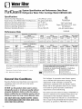
System Specification and Performance Data Sheet
Refrigerator Water Filter Cartridge Model U KF8001AXX
Specifications
Service Flow Rate (Maximum) .............................................0.78 GPM (:2.9 L/rain)
Rated Service Life UKF8001AXX-750 (Maximum) ......750 gallons/2839 liters
Maximum Operating Temperature .....................................100° F/38 ° C
Minimum Pressure Requirement ........................................35 psi/241 kPA
Minimum Operating Temperature ......................................33° F/1 ° C
Maximum Operating Pressure .............................................100 psi/689 kPA
1000 Apollo Road
Eagan, Minnesota 55121-2240
651.450.4913
EPA EST #35917-MN-1
Performance Data
Parameter
Clllorine
T&O
Particulate**
100834/B
USEPA
MCL
Standard No. 42: Aesthetic Effects
Influent
Challenge Concentration
2.0 mg/L ± 10%
Min. Required
Reduction
50%
Influent
Average
1.88 mg/L
5,700,000 #/ml
Effluent
Average Maximum
<0.05 mg/L 0.06 mg/L
30,583 #/ml 69_000 #/ml
% Reduction
Average Minimum
>9726% 96.84%
99.52% 98.94%
at least 1O,000 particles/ml 85%
Standard No. 53: Health Effects
InfluentUSEPA
MCL
1 NTU _*
99.5% Reduction
99% Reduction
0.015 mg/L
0.015 mg/L
0.002 mg/L
0.002 mg/L
0.0002 mg/L
0.003 mg/L
0.003 mg/L
Influent
Effluent
Parameter Challenge ConcentmUon Average Average Maximum Average
Turbidi b, 11 ± 1 NTU*** 10.73 NTU 0.36 NTU .049 NTU 9709%
Cysts Minimum 5O,000/L 220,000 #/L <1 <1 >99.99o/o
Asbestos 107108 fibers/L; fibers >10 nlicrz)meters in length 155 MF/L <1 <1 >99.99%
Lead at pH 6.5 0.15 mg/L ± 10% 0.153 mg/L <.001 <.001 >99.35%
Lead at pH 8.5 0.15 mg/L ± 10% 0.150 mg/L <.001 <.001 >99.35%
Mercury at pH 5.5 .006 mg/L ± 10% 0.006 mg/L 0.00026 0.0005 98.72%
Mercury at pH 8.5 .006 mg/L ± 10% 0.006 mg/L 0.0008 0.0015 98.72%
Lindane 0.002 mg/L ± 10% 0.002 mg/L 0.000025 0.00007 98.72%
Toxaphene 0.015 mg/L ± 10% 0.015 mg/L <0.001 <0.001 92.97%
Atrazine 0.009 mg/L ± 10% .00873 mg/L <0.002 <0.002 76.99%
% Reduction
Minimum
95.20%
>99.99%
>99.99%
>99.35%
>99.35%
90.910/o
75.930/o
96.500/o
91.67%
75.310/o
Mini Required
Reduction
0.5 NTU
>99.95%
99%
0.10 mg/L
0.10 mg/L
0.002 mg/L
0.002 mg/L
0.0002 mg/L
0.003 mg/L
0.003 mg/L
* Tested using a flow rate of 0.78 GPM; pressure of 60 psig; pH of 7.5 ± 0.5; temp. of
68 ° ± 5° F (20 ° ± 3 ° C] under standard laborato W conditions, however, actual
performance may vaiy. Health Clainl Perfornlance tested and certified by NSF
International
** Measurement in Particles/ml. Particles used were 0.5 - 1 microns
*** NTU - Nephelometric Turbidity units
Tested and certified by NSF International against ANSI/NSF Standards 42 & 53
in models UKFSOO1AXX-750 for the reduction of:
Standard No. 42: Aesthetic Effects | Standard No. 53: Health Effects
Taste and OdoT Reduction I Chenlical Reduction Unit
Chlorine Taste & Odo[ Lead, Atrazine, Lindane+ Mercury &
Mechanical Filtration Unit Toxaphene Reduction
Particulate Reduction Class 1 Mechanical Filtration Unit
CysL Turbidity and Asbestos Reduction
General Use Conditions
Read this Performance Data Sheet and compare the
capabilities of this unit with your actual water
treatment needs.
DO NOT use this product where water is micro-
biologically unsafe or of unknown quality without
adequate disinfection before or after the system.
System certified for cyst reduction may be used on
disinfected water that may contain filterable cysts.
USE ONLY WITH COLD WATER SUPPLY. CHECK
FOR COMPLIANCE WITH THE STATE AND LOCAL
LAWS AND REGULATIONS.
The PuriClean :_II retractable water filtration system
uses a UKF8001AXX replacement cartridge. Timely
replacement of filter cartridge is essential for
performance satisfaction from this filtration system.
Please refer to the applicable section of your Use &
Care Guide for general operation, maintenance
requirements and troubleshooting.
This system has been tested according to ANSI/NSF 42
and 53 for reduction of the substance listed above. The
concentration of the indicated substances in water
entering the system was reduced to a concentration less
than or equal to the permissible limit for water leaving
the system, as specified in ANSI/NSF 42 and 53.
19
Page is loading ...
Page is loading ...
Page is loading ...
Page is loading ...
Page is loading ...
Page is loading ...
Page is loading ...
Page is loading ...
Page is loading ...
Page is loading ...
Page is loading ...
Page is loading ...
Page is loading ...
Page is loading ...
Page is loading ...
Page is loading ...
Page is loading ...
-
 1
1
-
 2
2
-
 3
3
-
 4
4
-
 5
5
-
 6
6
-
 7
7
-
 8
8
-
 9
9
-
 10
10
-
 11
11
-
 12
12
-
 13
13
-
 14
14
-
 15
15
-
 16
16
-
 17
17
-
 18
18
-
 19
19
-
 20
20
-
 21
21
-
 22
22
-
 23
23
-
 24
24
-
 25
25
-
 26
26
-
 27
27
-
 28
28
-
 29
29
-
 30
30
-
 31
31
-
 32
32
-
 33
33
-
 34
34
-
 35
35
-
 36
36
-
 37
37


Maytag MCD2257HEB - 21.6 cu. Ft User guide
- Category
- Fridges
- Type
- User guide
Ask a question and I''ll find the answer in the document
Finding information in a document is now easier with AI
Related papers
-
Maytag MCS 67002813 Owner's manual
-
Maytag MBR2556KES Owner's manual
-
-
-
-
-
Amana GB2026PEKB Owner's manual
-
Amana MBF2256HEQ Owner's manual
-
-
Other documents
-
Admiral LTF2112ARZ Owner's manual
-
Jenn-Air JSD2789HEW Owner's manual
-
Jenn-Air JCB2285KES Owner's manual
-
Dometic NRX Clip Installation guide
-
AGA fridge Side by Side manual Owner's manual
-
Whirlpool ETZOZK User manual
-
Hettich 9243084 User manual
-
ATEN EA1442 Quick start guide
-
-
Whirlpool 6ED25DQ User manual