Patton electronic Switch 2701/I User manual
- Category
- Network switches
- Type
- User manual
This manual is also suitable for

USER
MANUAL
MODEL 2701/I
G.703/G.704 NTU with
10Base-T Ethernet
Interface
SALES OFFICE
(301) 975-1000
TECHNICAL SUPPORT
(301) 975-1007
Part# 07M2701I-UM
Doc# 08609U2-001
Rev. I
Revised 2/18/08
An ISO-9001Certified
Company
Important—This is a Class A device and is
intended for use in a light industrial environ-
ment. It is not intended nor approved for use
in an industrial or residential environment.

2
CONTENTS
1.0 Warranty & Compliance Information ........................................ 4
1.1 Compliance................................................................................... 4
EMC Compliance.......................................................................... 4
Safety Compliance: ...................................................................... 4
PSTN Regulatory Compliance:..................................................... 4
1.2 CE Notice...................................................................................... 5
1.3 Authorized European Representative........................................... 5
1.4 Service.......................................................................................... 5
1.5 Safety When Working With Electricity .......................................... 6
2.0 General Information.................................................................... 7
2.1 Features........................................................................................ 7
2.2 Description.................................................................................... 7
3.0 PPP Operational Background.................................................... 9
3.1 Applications .................................................................................. 9
4.0 Configuration ............................................................................ 11
4.1 DIP Switch Configuration............................................................ 11
Switch SW1 ................................................................................ 12
Switch SW-1 through SW1-5 ............................................... 12
SW1-6 and SW1-7 Clock Modes ......................................... 13
Switch SW2 ................................................................................ 14
Switch SW2-1 Line Coding: HDB3 (default) ........................ 14
Switch SW2-2: CRC-4 Multiframe ....................................... 15
Switch SW2-3 Data Inversion .............................................. 15
Switch SW2-4: Remote Digital Loopback Type ................... 15
Switch SW2-5 Front Panel Switches ................................... 16
Switch SW2-6: V.54 Response Disabled (default) .............. 16
5.0 Installation................................................................................. 17
5.1 Connecting to the G.703 Network............................................... 17
Connecting Dual Coaxial Cable (75 ohm) to the G.703 Network 17
Opening the Case....................................................................... 18
Connecting the Twisted Pair (120 ohm) to the G.703 Network .. 18
5.2 Connecting the 10Base-T Ethernet Port to a PC (DTE) ............. 19
5.3 Connecting the 10Base-T Ethernet Port to a Hub ...................... 19
5.4 Power Connection ...................................................................... 20
Universal AC Power (100–240 VAC).......................................... 20
DC Power ................................................................................... 20
6.0 Operation................................................................................... 21
6.1 Power-up .................................................................................... 21
6.2 LED Status Monitors................................................................... 21
6.3 Loop (V.54 & Telco) Diagnostics ................................................ 23
Operating Local Loopback (LL) .................................................. 23
Operating Remote Digital Loopback (RL)................................... 24
CSU Loop ................................................................................... 24
Using the V.52 (BER) Test Pattern Generator ........................... 25

3
A
Specifications ........................................................................... 26
A.1 Network Data Rate ...................................................................... 26
A.2 Network Connector ..................................................................... 26
A.3 Nominal Impedance ................................................................... 26
A.4 Line Coding ................................................................................ 26
A.5 Line Framing ............................................................................... 26
A.6 CRC-4 Multiframing .................................................................... 26
A.7 Clocking ...................................................................................... 26
A.8 Time Slot Rate ............................................................................. 26
A.9 Network Data Rates .................................................................... 26
A.10 Distance ...................................................................................... 26
A.11 Power Supply .............................................................................. 26
A.12 Humidity ...................................................................................... 27
A.13 Temperature ............................................................................... 27
A.14 Dimensions ................................................................................. 27
B
Ethernet 10Base-T Specifications........................................... 28
B.1 DTE Interface .............................................................................. 28
B.2 DTE Data Rates .......................................................................... 28
B.3 LAn Connection .......................................................................... 28
B.4 Protocol ....................................................................................... 28
B.5 MAC Address Table Size ............................................................ 28
B.6 MAC Address Aging ................................................................... 28
B.7 Frame Buffer ............................................................................... 28
B.8 Frame Latency ............................................................................ 28
B.9 Diagnostics ................................................................................. 28
B.10 Indicators .................................................................................... 28
B.11 Configuration .............................................................................. 28
C
Factory Replacement Parts and Accessories........................ 29

4
1.0 WARRANTY & COMPLIANCE INFORMATION
Patton Electronics warrants all Model 2701/I components to be free from
defects, and will—at our option—repair or replace the product should it
fail within one year from the first date of shipment.
This warranty is limited to defects in workmanship or materials, and does
not cover customer damage, abuse, or unauthorized modification. If this
product fails or does not perform as warranted, your sole recourse shall
be repair or replacement as described above. Under no condition shall
Patton Electronics be liable for any damages incurred by the use of this
product. These damages include, but are not limited to, the following:
lost profits, lost savings and incidental or consequential damages arising
from the use of or inability to use this product. Patton Electronics specif-
ically disclaims all other warranties, expressed or implied, and the instal-
lation or use of this product shall be deemed an acceptance of these
terms by the user.
1.1 COMPLIANCE
EMC Compliance
• EN55022, Class A
• EN55024
Safety Compliance:
• EN 60950-1
• AS/NZS 60950-1
PSTN Regulatory Compliance:
• TBR 12 & 13
• AS/ACIF S016:2001

5
1.2 CE NOTICE
We certify that the apparatus identified in this document conforms to the
requirements of Council Directive 1999/5/EC on the approximation of the
laws of the member states relating to Radio and Telecommunication Ter-
minal Equipment and the mutual recognition of their conformity.
The safety advice in the documentation accompanying this product shall
be obeyed. The conformity to the above directive is indicated by the CE
sign on the device.
1.3 AUTHORIZED EUROPEAN REPRESENTATIVE
D R M Green
European Compliance Services Limited.
Oakdene House, Oak Road
Watchfield, Swindon, Wilts SN6 8TD, UK
1.4 SERVICE
All warranty and nonwarranty repairs must be returned freight prepaid
and insured to Patton Electronics. All returns must have a Return Mate-
rials Authorization number on the outside of the shipping container. This
number may be obtained from Patton Electronics Technical Services at:
• Tel: +1 (301) 975-1007
• Email: [email protected]
• URL: http://www.patton.com
Note Packages received without an RMA number will not be
accepted.
Patton Electronics' technical staff is also available to answer any ques-
tions that might arise concerning the installation or use of your Patton
Model 2701/I. Technical Service hours: 8AM to 5PM EST, Monday
through Friday.

6
1.5 SAFETY WHEN WORKING WITH ELECTRICITY
• This device contains no user serviceable parts. The
equipment shall be returned to Patton Electronics for
repairs, or repaired by qualified service personnel.
• The external power adapter shall be a listed Limited
Power Source. Ensure that the power cable used meets
all applicable standards for the country in which it is to
be installed, and that it is connected to a wall outlet
which has earth ground. The mains outlet that is uti-
lized to power the devise shall be within 10 feet (3
meters) of the device, shall be easily accessible, and
protected by a circuit breaker.
• Hazardous network voltages are present in WAN ports
regardless of whether power to the unit is ON or OFF. To
avoid electric shock, use caution when near WAN ports.
When detaching the cables, detach the end away from
the device first.
• Do not work on the system or connect or disconnect
cables during periods of lightning activity.
In accordance with the requirements of council direc-
tive 2002/96/EC on Waste of Electrical and Electronic
Equipment (WEEE), ensure that at end-of-life you sepa-
rate this product from other waste and scrap and deliver
to the WEEE collection system in your country for recy-
cling.
This device is not intended to be connected to the public
telephone network.
WARNING
WARNING

7
2.0 GENERAL INFORMATION
Thank you for your purchase of this Patton Electronics product. This
product has been thoroughly inspected and tested and is warranted for
One Year parts and labor. If any questions or problems arise during
installation or use of this product, please do not hesitate to contact Pat-
ton Electronics Technical Support at (301) 975-1007.
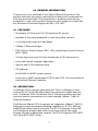
2.1 FEATURES
• Terminates G.703 and G.704, E1/fractional E1 service
• Available in low-cost standalone or rack-mountable versions
• n x 64 kbps data rates to 2.048 Mbps
• 10Base-T Ethernet bridge
• PPP (Point to Point Protocol, RFC 1661) with Bridge Control Protocol
(RFC 1638)
• 75-ohm dual coax and 120-ohm twisted-pair G.703 connections
• Local and remote loopback diagnostics
• Internal and G.703 network timing
• CE approval
• 90-260VAC & 48VDC power options
• Conforms to ONP requirements CTR 12 and CTR 13 for connection to
international Telecom networks
2.2 DESCRIPTION
The Model 2701/I receives channelized G.704 (n x 64kbps) or clear
channel E1/G.703 (2.048-Mbps) data from the telco's digital data net-
work. The Model 2701/I terminates the G.703 telco interface and con-
verts the data for transmission to a user-oriented 10Base-T (802.3)
Ethernet interface.
The Ethernet (Model 2701/I) supports an integrated 10Base-T (802.3)
Ethernet port with transparent bridging capability for IP, IPX, DECnet,
NetBIOS and other layer-3 protocols. The 2701/I attaches to the LAN
and intelligently bridges data traffic to the large central site router
through the telco's leased line network. The 2701/I supports PPP (RFC
1661) and BCP (RFC 1638).

8
The Model 2701/I is a 10Base-T bridge that operates over G.703/G.704
lines. It uses MAC learning and forwarding to provide seamless LAN-to-
LAN connectivity. As a result, corporate enterprises can connect their
servers to a pair of NTUs and automatically forward data packets that are
meant for the remote network. Local packets are filtered and passed only
to the local LAN.

9
3.0 PPP OPERATIONAL BACKGROUND
PPP is a protocol used for multi-plexed transport over a point-to-point
link. PPP operates on all full duplex media, and is a symmetric peer-to-
peer protocol, which can be broken into three main components: 1. A
standard method to encapsulate datagrams over serial links; 2. A Link
Control Protocol (LCP) to establish, configure, and test the data-link con-
nection; 3. A family of Network Control Protocols (NCPs) to establish and
configure different network layer protocols.
In order to establish communications over a point-to-point link, each end
of the PPP link must first announce its capabilities and agree on the
parameters of the link’s operation. This exchange is facilitated through
LCP Configure-Request packets.
Once the link has been established and optional facilities have been
negotiated, PPP will attempt to establish a network protocol. PPP will
use Network Control Protocol (NCP) to choose and configure one or
more network layer protocols. Once each of the network layer protocols
have been configured, datagrams from the established network layer
protocol can be sent over the link. The link will remain configured for
these communications until explicit LCP or NCP packets close the link
down, or until some external event occurs.
The PPP Bridging Control Protocol (BCP), defined in RFC 1638, config-
ures and enables/disables the bridge protocol on both ends of the point-
to-point link. BCP uses the same packet exchange mechanism as the
Link Control Protocol (LCP). BCP is a Network Control Protocol of PPP,
bridge packets may not be exchanged until PPP has reached the net-
work layer protocol phase.
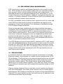
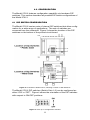
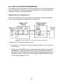
3.1 APPLICATIONS
In situations where a routed network requires connectivity to a remote
Ethernet network, the interface on a router can be configured as a PPP
IP Half Bridge. The serial line to the remote bridge functions as a Virtual
Ethernet interface, effectively extending the routers serial port connec-
tion to the remote network. The bridge device sends bridge packets
(BPDU's) to the router's serial interface. The router will receive the layer
three address information and will forward these packets based on its IP
address.
Figure 1 shows a typical Cisco router with a serial interface configured
as a PPP Half Bridge. The router serial interface uses a remote device
that supports PPP bridging to function as a node on the remote Ethernet
network. The serial interface on the Cisco will have an IP address on the
same Ethernet subnet as the bridge.

10
Figure 1. Cisco router with serial interface, configured as PPP Half Bridge.
For example, the customer site is assigned the addresses 192.168.1.0/
24 through 192.168.1.1/24. The address 192.168.1.1/24 is also the
default gateway for the remote network. The above settings remove any
routing/forwarding intelligence from the CPE. The associated Cisco con-
figuration will set serial interface (s0) to accommodate half bridging for
the above example.
Authentication is optional under PPP. In a point-to-point leased-line link,
incoming customer facilities are usually fixed in nature, therefore authen-
tication is generally not required. If the foreign device requires authenti-
cation via PAP or CHAP, the PPP software will respond with default Peer-
ID consisting of the units Ethernet MAC address and a password which
consists of the unit’s Ethernet MAC address.
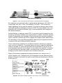
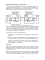
Some networking systems do not define network numbers in packets
sent out over a network. If a packet does not have a specific destination
network number, a router will assume that the packet is set up for the
local segment and will not forward it to any other sub-network. However,
in cases where two devices need to communicate over the wide-area,
bridging can be used to transport non-routable protocols.
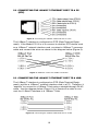
Figure 2 illustrates transparent bridging between two routers over a
serial interface (s0). Bridging will occur between the two Ethernet Inter-
faces on Router A (e0 and e1) and the two Ethernet Interfaces on Router
B (e0 and e1).
Figure 2. Transparent bridging between two routers over a serial interface

11
4.0 CONFIGURATION
The Model 2701/I features configuration capability via hardware DIP
switches. This section describes all possible DIP switch configurations of
the Model 2701/I.
4.1 DIP SWITCH CONFIGURATION
The Model 2701/I has two sets of internal DIP switches that allow config-
uration for a wide range of applications. The sets of switches are
accessed from the underside. Figure 3 shows the location of the DIP
switches on the bottom of the printed circuit board.
Figure 3. Underside of Model 2701/I, Showing Location of DIP Switches
The Model 2701/I DIP switches (Switch Sets 1-2) can be configured as
either “ON” or “OFF”. Figure 4 shows the orientation of the DIP switches
with respect to ON/OFF positions.
Figure 4. Close up of configuration switches

12
Switch SW1
A detailed description of each switch (SW1-1 through SW1-5) setting fol-
lows the summary table below:
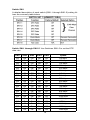
Switch SW-1 through SW1-5. Use Switches SW1-5 to set the DTE
data rate.
SW1 SW2 SW3 SW4 SW5 Speed
On On On On On 64 kbps
Off On On On On 128 kbps
On Off On On On 192 kbps
Off Off On On On 256 kbps
On On Off On On 320 kbps
Off On Off On On 384 kbps
On Off Off On On 448 kbps
Off Off Off On On 512 kbps
On On On Off On 576 kbps
Off On On Off On 640 kbps
On Off On Off On 704 kbps
Off Off On Off On 768 kbps
On On Off Off On 832 kbps
Off On Off Off On 896 kbps
On Off Off Off On 960 kbps
Off Off Off Off On 1024 kbps
On On On On Off 1088 kbps
Off On On On Off 1152 kbps
On Off On On Off 1216 kbps
Off Off On On Off 1280 kbps
On On Off On Off 1344 kbps

13
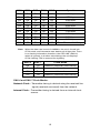
Note When the data rate is set to 2.048Mb/s, the unit is forced into
G.703 mode, and it transmits user data on all 32 time-lots. There
is no framing information; therefore, the CRC4 MF (SW2-2)
switch is ignored. In all other rate settings, the unit employs
G.704 framing; TS0 is reserved for signaling.
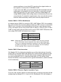
SW1-6 and SW1-7 Clock Modes.
Network Clock—Transmitter timing is derived using the received line
signal (received recovered) from the network.
Internal Clock—Transmitter timing is derived from an internal clock
source.
Off On Off On Off 1408 kbps
On Off Off On Off 1472 kbps
Off Off Off On Off 1536 kbps
On On On Off Off 1600 kbps
Off On On Off Off 1664 kbps
On Off On Off Off 1728 kbps
Off Off On Off Off 1792 kbps
On On Off Off Off 1856 kbps
Off On Off Off Off 1920 kbps
On Off Off Off Off 1984 kbps
Off Off Off Off Off Clear Channel 2048 kbps
SW1-6 SW1-7 Clock Mode
On On Network (Received Recovered)
On Off Internal
Off On Internal
Off Off Network (Received Recovered)
SW1 SW2 SW3 SW4 SW5 Speed

14
Switch SW2
A detailed description of each switch (SW1-1 through SW1-5) setting fol-
lows the summary table below:
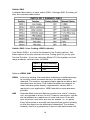
Switch SW2-1 Line Coding: HDB3 (default).
Use Switch SW2-1 to control the Network Line Coding options. Set
these options to be the same as the Line Coding given to you by your
Service Provider. If you are using two Model 2701/Is together as short
range modems, set both units to HDB3.
Options: HDB3, AMI
HDB3 In this line coding, the transmitter substitutes a deliberate bipo-
lar violation when excessive zeros in the data stream are
detected. The receiver recognizes these special violations and
decodes them as zeros. This method enables the network to
meet minimum pulse density requirements. Unless AMI is
required in your application, HDB3 should be used whenever
possible.
AMI Alternate Mark Inversion defines a pulse as a “mark,” a binary
one, as opposed to a zero. In an E1 network connection, signals
are transmitted as a sequence of ones and zeros. Ones are
sent as pulses, and zeros are sent as spaces, i.e., no pulse.
Every other pulse is inverted from the previous pulse in polarity,
so that the signal can be effectively transmitted. This means,
however, that a long sequence of zeros in the data stream will
SW2-1 Line Encoding
Off HDB3
On AMI

15
cause problems, since the NTU receiving the signal relies on
the signal to recover the 2.048 Mb/s clock.
If you must use AMI, you should ensure that the data terminal
equipment connected to the unit provides a minimally accept-
able pulse density. For this reason, there are advantages to
using HDB3 instead. AMI coding does not inherently account for
ones density. To meet this requirement, the user should ensure
that the data inherently meets pulse density requirements.
Switch SW2-2: CRC-4 Multiframe.
In framed mode, SW2-2 is used for CRC-4 MF. When CRC-4 is enabled,
the unit monitors the incoming data stream for CRC-4 errors. It transmits
CRC-4 error counts to the transmitting unit. When using timeslot zero
(TS0), excessive errors may cause loss of frame or loss of sync. If CRC-
4 MF is used, both units must be set for set for CRC-4 MF. Otherwise, the
one using CRC-4 MF will detect loss of sync.
Note When the data rate is set to 2.048Mb/s, then the unit is forced
into G.703 mode, and it transmits user data on all 32 time-lots.
There is no framing information; therefore, the CRC4 MF (SW2-
2) switch is ignored. In all other rate settings, the unit employs
G.704 framing; TS0 is reserved for signaling.
Switch SW2-3 Data Inversion.
Set Switch S2-3 to determine whether or not the data stream from the
local DTE is inverted within the Model 2701 before being passed to the
G.703/G.704 network. An inverted data stream may be required when
you use the Model 2701 to communicate with a G.703 device (that
inverts the data) on the remote end. In typical installations, data inversion
is not necessary.
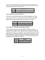
Switch SW2-4: Remote Digital Loopback Type.
The user can set this switch to select the type of remote loop that will be
initiated by the Model 2701. If set to V.54, the Model 2701 will initiate a
SW2-2 Option
Off CRC-4 Disabled
On CRC-4 Enabled
SW2-3 Option
Off Data not inverted
On Data inverted

16
V.54 loop when Remote Loop is selected by the front panel switches. If
set to CSU, the Model 2701 will initiate a CSU loop when Remote Loop
is selected by the front panel switches.
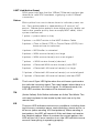
Switch SW2-5 Front Panel Switches.
As the Front Panel Switches may be inadvertently toggled, or in the
event that the end-user may not need to use the switches, the installer
may disable the front panel switches. Set Switch S2-5 to determine
whether the front-panel toggle switches are active or inactive.
Switch SW2-6: V.54 Response Disabled (default).
V.54 Response is a special in-band loopback facility that sends a
pseudo-random pattern over the data stream. This is the only loopback
that the unit can initiate. This is useful for campus applications when you
need to put a remote unit in loopback. The unit responds to the V.54 loop-
back command, and the whole process takes only a few seconds to com-
plete. When V.54 Loopback is disabled, the unit will not be able to send
or respond to V.54 loopback commands. The duration of the loopback is
limited by the loopback timeout setting.
S2-4 RDL Type
Off Initiate a V.54 RDL loop when selected
On Initiate a CSU loopback when selected
SW2-5 Option
Off Front Panel Switches Enabled
On Front Panel Switches Disabled
SW2-6 Option
Off V.54 Response Enabled
On V.54 Response Disabled

17
5.0 INSTALLATION
Once the Model 2701/I is properly configured, it is ready to connect to
the G.703/G.704 interface, to the Ethernet port, and to the power source.
This section describes how to make these connections.
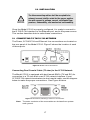
5.1 CONNECTING TO THE G.703 NETWORK
The Power, G.703/G.704 and Ethernet Line connections are located on
the rear panel of the Model 2701/I. Figure 5 shows the location of each
of these ports.
Figure 5. Model 2701/I Rear Panel
Connecting Dual Coaxial Cable (75 ohm) to the G.703 Network
The Model 2701/I is equipped with dual female BNCs (TX and RX) for
connection to a 75 ohm dual coax G.703 network interface. If your
G.703/G.704 network terminates via dual coaxial cable, use the diagram
below to make the proper connections. See Figure 6 below.
Figure 6. Rear Panel, Showing Location of Connectors.
Note The outer conductor of the coax cables are isolated from system
earth ground.
The Interconnecting cables shall be acceptable for
external use and shall be rated for the proper applica-
tion with respect to voltage, current, anticipated tem-
perature, flammability, and mechanical serviceability.
WARNING

18
When using the 75 Ohm interface, jumper straps JP2, JP6, and JP7
must be installed over the jumpers. The jumpers are located next to the
BNC connectors. Refer to the following section to open the case.
Opening the Case
Open the case by inserting a screwdriver into the slots and twist the
screwdriver head slightly. The top half of the case will separate from the
lower half of the case. Take caution not to damage any of the PC board
mounted components.
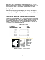
Connecting the Twisted Pair (120 ohm) to the G.703 Network
The Model 2701/I is equipped with a single RJ-48C jack for connections
to a 120 ohm twisted pair G.703/G.704 network interface. If your G.703/
G.704 network terminates via RJ-48C, use the connection diagram
(Figure 7) following the pinout and signals chart below to connect the
120 ohm G.703/G.704 network channel.
Figure 7. G.703/G.704 170 ohm Connection.
1
2
3
4
5
6
7
8
1
2
3
4
5
6
7
8
(RX) Receive (Ring)
(RX) Receive (Tip)
Shield
(TX) Transmit (Ring)
(TX) Transmit (Tip)
Shield
No connection
No connection
Signal NameRJ-48C Jack

19
5.2 CONNECTING THE 10BASE-T ETHERNET PORT TO A PC
(DTE)
Figure 8. Connecting the 10Base-T Ethernet Port to a PC
The 10Base-T interface is configured as DTE (Data Terminal Equip-
ment). If the Model 2701/I is to to connect to another DTE device such
as a 10Base-T network interface card, construct a 10Base-T crossover
cable and connect the wires as shown in the diagram below (Figure 9).
Figure 9. 10Base-T Cross-over Cable Connection
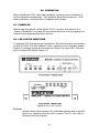
5.3 CONNECTING THE 10BASE-T ETHERNET PORT TO A HUB
The 10Base-T interface is configured as DTE (Data Terminal Equip-
ment), just like a 10Base-T network interface card in a PC. Therefore, it
“expects” to connect to a 10Base-T Hub using a straight-through RJ-45
cable. Use the diagram below (Figure 10) to construct a cable to con-
nect the 10 BaseT interface to a 10Base-T Hub.
Figure 10. Connecting the 10Base-T Ethernet Port to a Hub

20
5.4 POWER CONNECTION
Universal AC Power (100–240 VAC)
The Model 2701/I uses a 5VDC, 2A universal input 100-240VAC, power
supply (center pin is +5V). The universal input power supply has a male
IEC-320 power entry connector. This power supply connects to the
Model 2701/I by means of a barrel jack on the rear panel. Many interna-
tional power cords are available for the universal power supply.
The Model 2701/I powers up as soon as it is plugged into an AC outlet--
there is no power switch..
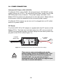
DC Power
The 36-60 VDC DC to DC adapter is supplied with the DC version of the
Model 2701/I. The black and red leads plug into a DC source (nominal
48VDC) and the barrel power connector plugs into the barrel power sup-
ply jack on the 2701/I. (See Figure 11).
Figure 11. Connecting DC Power to the 2701 DC Power Supply.
There are no user-serviceable parts in the
power supply section of the Model 2701. Con-
tact Patton Electronics Technical support at
(301)975-1007, via our web site at http://
www.patton.com, or by e-mail at support@pat-
ton.com, for more information.
To Power
Supply Jack
To -48VDC
Source
-Vin
+Vin
SWITCHING POWER SUPPLY
MODEL : SYD1106-0505
INPUT : 36-60V 0.2A MAX
OUTPUT : +5V 1.0A
OUTPUT POWER : 5W MAX
S/N: G01234567890
MADE IN CHINA BY SUNNY
Black lead (-V)
Red lead (+V)
Barrel power connector
WARNING
Page is loading ...
Page is loading ...
Page is loading ...
Page is loading ...
Page is loading ...
Page is loading ...
Page is loading ...
Page is loading ...
Page is loading ...
Page is loading ...
Page is loading ...
Page is loading ...
-
 1
1
-
 2
2
-
 3
3
-
 4
4
-
 5
5
-
 6
6
-
 7
7
-
 8
8
-
 9
9
-
 10
10
-
 11
11
-
 12
12
-
 13
13
-
 14
14
-
 15
15
-
 16
16
-
 17
17
-
 18
18
-
 19
19
-
 20
20
-
 21
21
-
 22
22
-
 23
23
-
 24
24
-
 25
25
-
 26
26
-
 27
27
-
 28
28
-
 29
29
-
 30
30
-
 31
31
-
 32
32


Patton electronic Switch 2701/I User manual
- Category
- Network switches
- Type
- User manual
- This manual is also suitable for
Ask a question and I''ll find the answer in the document
Finding information in a document is now easier with AI
Related papers
-
Patton electronic 2701/B User manual
-
Patton electronics 2701/B User manual
-
-
-
-
-
-
-
-
Other documents
-
Patton SmartNode 41 Series User manual
-
 Telstrat NTU-45 User manual
-
Patton 1088k User manual
-
-
 Telenetics DSP 9612 User manual
-
Keithley 2701 User manual
-
RAD Data comm RIC-E1 User manual
-
CTC Union ETU011U User manual
-
Kramer Electronics BCP-5X-SOLID-1000 Datasheet
-

