Page is loading ...

PRO35-115 & PRO35-115RD
115/230 Volt
PRO35-115AD Automatic Diesel Nozzle
PRO35-115MD Manual Diesel Nozzle
PRO35-115PO Pump Only
PRO35-115RD For Remote Dispensing Systems
PRO35-115PO/XTS Pump Only - Extreme Temperature Series
922108-01D11/14
To the owner...
Congratulations on receiving your GPRO™ Fuel Transfer
Pump. We are pleased to provide you with a system designed
to give you maximum reliability and efciency.
Your fuel pump is designed, tested, and approved for use with
gasoline, kerosene, and diesel fuel. Please take all due pre-
cautions when handling these ammable liquids. Your safety
is important to us.
Also, to assure the longest possible service life, it is important
that you follow the operation and maintenance procedures
outlined in this manual. We are proud to provide you with a
quality product and dedicated support. Together with your
conscientious use, we are sure that you will obtain years of
safe, dependable service.
Victor Lukic, President
Great Plains Industries, Inc.
TABLE OF CONTENTS
General Information .................................................... 2
Safety Instructions ...................................................... 2
Installation .................................................................. 2
Operation .................................................................... 4
Troubleshooting .......................................................... 5
Illustrated Parts Drawing ............................................ 6
Specications ............................................................. 7
Parts and Service ....................................................... 7
Warranty .......................................................See Insert
SAVE THESE INSTRUCTIONS
DO NOT RETURN THIS PRODUCT
TO THE STORE!
Please contact Great Plains Industries before returning any
product. If you are missing parts or experience problems with
your installation, our Customer
Support Department will
be happy
to assist you:
800-835-0113 or 316-686-7361
OWNER'S MANUAL

2922108-01D PRO35-115 / PRO35-115RD
GENERAL INFORMATION
Your pump is designed for use only with thin viscosity
petroleum fuels such as gasoline (up to 15% alcohol
blends such as E15), diesel fuel (up to 20% biodiesel
blends such as B20) and kerosene. Do not use this pump
for dispensing any uids other than those for which it was
designed. Using the pump with other fuels can damage
components and void the warranty. Use of alcohol blends
above 10% (E10) and biodiesel blends above 5% (B5)
have not been reviewed by UL.
Model Components
PRO35-115AD: Includes pump, hose and automatic
diesel nozzle.
PRO35-115MD: Includes pump, hose and manual diesel
nozzle.
PRO35-115PO: Includes pump only.
PRO35-115RD: Includes dedicated pump only for remote
dispensing systems.
PRO35-115PO/XTS: Includes pump only and compo-
nents to assemble to unit before use.
NOTE: Sufxes MD, AD, PO and PO/XTS are for order-
ing purposes only. Constructions described above are
covered as alternate constructions under the Part No.
PRO35 UL Listing.
How to Use This Manual
The purpose of this manual is to assist you in installing,
operating and maintaining your GPRO™ pump. If you
need additional assistance, contact your GPRO dealer or
the Great Plains Industries Customer Service Department.
SAFETY INSTRUCTIONS
The following safety alert symbols are used in
this manual. Obey all safety messages that follow
this symbol to avoid possible injury or death.
DANGER DANGER indicates an
imminently hazardous
situation which, if not avoid-
ed, will result in death or
serious injury.
WARNING WARNING indicates
a potentially hazardous
situation which, if not avoid-
ed, could result in death or
serious injury.
CAUTION CAUTION indicates
a potentially hazardous
situation which, if not avoid-
ed, may result in minor or
moderate injury.
CAUTION CAUTION used without
the safety alert symbol
indicates a potentially
hazardous situation which,
if not avoided, may result in
property damage.
There are inherent dangers wherever ammable fuel and
AC electrical sources are in close proximity.
Static electricity as a source of sparking is always a
concern and requires extreme care in the installation and
operation of your entire fuel transfer system.
Additional components such as meters, automatic nozzles
and lters must be listed for use with fuel transfer systems.
The ow of fuel through a hose and nozzle can generate
static electrical charges and dangerous sparking can
result in re or explosion. Hoses and nozzles must be
electrically conductive and bonded to ground.
It is your responsibility to:
• Know and follow applicable national, state and local
safety codes pertaining to installing and operating
electrical equipment for use with ammable liquids.
• Know and follow all safety precautions when handling
petroleum fuels.
• Ensure that all equipment operators have access to
adequate instructions concerning safe operating and
maintenance procedures.
INSTALLATION
Mechanical Connections
Coverplates protect the operator from moving parts. Never
operate the pump without coverplates in place. Never apply
electric power to the pump without coverplates in place.
Always disconnect power before repairing or servicing.
WARNING
All threaded fuel connections must be sealed with thread
tape or a pipe thread sealing compound approved for
use with petroleum fuels.
Your pump must be mounted on a vented tank. If the
tank is not vented, contact your GPRO distributor for
the correct vent cap.
This pump has a built-in check valve to keep the pump
primed. No additional check valve is required on suction
pipes shorter than 15 ft. (4.6 m). Make sure any check
valves or foot valves used are equipped with proper
pressure relief valves.
Your pump is designed to mount directly to a standard
2 in. female tank tting. For the suction pipe, a 1¼ in.
galvanized steel pipe cut to length and threaded on one
end may be used. Suction pipe should extend to within
3 inches of tank bottom. Apply thread tape to the suc-
tion pipe thread and securely tighten the suction pipe to
the tank adapter. Once suction pipe is attached to tank
adapter, insert suction pipe into tank and tighten tank
adapter to tank tting.

3922108-01D PRO35-115 / PRO35-115RD
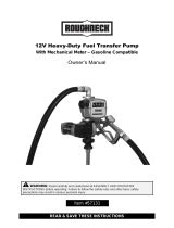
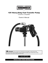
Install Nozzle Hanger
(Not applicable to pumps with -RD sufx)
Attention: The nozzle hanger for your pump was removed
before shipping to protect against damage.
To reinstall the nozzle hanger follow the steps below.
1. Remove the two ¼"-20 x ½" bolts and the two at
washers from the switch coverplate.
2. Place the two bolts through the nozzle cover and then
place the two at washers on the bolts. The washers
are used as spacers to set the nozzle hanger away
from the switch coverplate.
3. Align the bolts with the two threaded holes on the
switch coverplate; thread the bolts into the holes.
Torque bolts to 45-60 in/lb (Figure 1).
FIGURE 1
Switch Locking Lever
Attention: The PRO35-115RD remote dispenser pump
incorporates an external switch locking lever that locks the
pump switch in the “ON” position. The pump is typically
shut off using the remote dispensing device “ON-OFF”
mechanism.
Electrical Connections
Pump must be installed by a licensed electrician and conform
to National Fire Protection Association (NFPA) codes 30 and 70.
You, as the owner, are responsible for seeing that the installation
and operation of your pump complies with NFPA codes as well
as any applicable state and local codes. Rigid conduit must be
used to install wiring.
Failure to follow these wiring instructions may result in death or
serious injury from shock, re or explosion.
The pump must be properly grounded to avoid personal injury.
Operating an ungrounded or improperly grounded pump may result
in death due to electrical shock, re or explosion.
DANGER
Electrical wiring and connections must be made only by
a licensed electrician in accordance with national, state
and local electrical codes regarding Class I, Division 1,
Group D locations. Other codes may apply.
Thread for the conduit connection at the pump electrical
box is ½ in. FNPT.
A standard 15-amp breaker is recommended.
This pump is equipped with an auxiliary AC accessory
lead. The third wire (red) is to be used to energize a
control circuit that operates a device such as a signal
light or a solenoid operated valve. Maximum amp draw
on the control circuit is 1 amp. If you do not need this
feature, ensure that the wire is insulated and enclosed
within the electrical cavity of the pump.
Connect pump to the proper voltage source. PRO35 series pumps
are designed to operate on 115 VAC, 60 HZ or 230 VAC, 60 HZ.
Connection to improper voltage will damage pump. Pump is set
at factory for low voltage (115-volt). For high voltage applications
(230-volt) see wiring diagram located inside electrical coverplate.
CAUTION
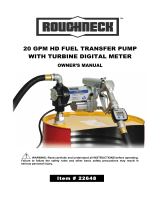
Wiring Details
1. Remove electrical coverplate (Figure 2). Install con-
duit and cable from switchbox to pump electrical box.
Wiring must be in accordance with Class I, Division 1
requirements in the applicable national electrical code.
A
DETAIL A
SCALE .75
FIGURE 2
2. Attach ground wire using the green ground screw lo-
cated inside the electrical box (Figure 3). Connect the
power cable to the pump wiring per the wiring diagram
located inside the electrical coverplate. Secure with
wire nuts.
FIGURE 3
3. Position wires inside the electrical box. Replace
electrical coverplate with all seven screws and tighten
securely.

4922108-01D PRO35-115 / PRO35-115RD
OPERATION
To prevent physical injury, observe precautions against re or
explosion when dispensing fuel. Do not operate the system in
the presence of any source of ignition including running or hot
engines, lighted cigarettes, or gas or electric heaters.
DANGER
Observe precautions against electrical shock when operating the
system. Serious or fatal shock can result from operating electrical
equipment in damp or wet locations.
WARNING
Avoid prolonged skin contact with petroleum fuels. Use protective
goggles, gloves and aprons in case of splashing or spills. Change
saturated clothing and wash skin promptly with soap and water.
CAUTION
To dispense fuel (for pumps with nozzle
hanger):
1. Remove the nozzle from the holder. Turn the pump
on by pulling the switch lever down.
2. Insert the nozzle into the receiving tank and squeeze
the handle to dispense fuel.
3. After dispensing fuel, push the switch lever up to turn
the pump off and return the nozzle to the holder. The
nozzle may be locked in place to prevent unauthorized
use.
The pump contains an automatic bypass valve to prevent
pressure buildup when the pump is on but the nozzle
is closed. Do not leave the pump on for more than 10
minutes with the nozzle closed.
Never leave the pump running without uid. Dry running
can damage the pump components.
The pump has a duty cycle of 30 minutes ON and 30
minutes OFF. Do not overheat. Allow the motor to cool
the same length of time it was in operation.
The fuel strainer and check valve assembly should be
cleaned on a regular basis or if low owrate is noticed.
If the pump becomes too hot, an internal temperature-
limiting device will automatically shut the motor off and
prevent operation until it cools.
Always turn the pump off if the temperature-
limiting
device trips. The Remote Dispenser pump (PRO35-115RD) turns
off at the dispensing device. If left on, the pump will automatically
reset when cool and start pumping.
CAUTION

5922108-01D PRO35-115 / PRO35-115RD
TROUBLESHOOTING – DONE CORRECTLY - - IN TABLES
SYMPTOM PROBABLE CAUSE CORRECTIVE ACTION
A. MOTOR DOES
NOT RUN
1. No electrical power to pump Check breaker, switchbox and wiring.
2. Auxiliary temperature-limiting
device tripped
Allow motor to cool. Auxiliary temperature-limiting device will automati-
cally reset.
3. Rotor or vanes jammed Remove coverplate and check for damage or obstruction.
B. MOTOR RUNS
BUT DOES NOT
PUMP FLUID
1. Tank level low Add fuel to tank.
2. Clogged lter assembly Remove and clean lter assembly.
3. Clogged or broken suction pipe Remove pump and clear suction pipe, replace as needed.
4. Broken shaft key Replace shaft key. Check rotor or vanes for obstruction
C. PUMP FAILS TO
PRIME
1. Air leak in system Check for air leaks at all joints
2. Bypass valve stuck open Remove bypass valve and clean or replace as needed.
3. Check valve stuck open Remove check valve and clean or replace as needed.
4. Rotor or vanes worn Check rotor and vanes for excessive wear.
D. LOW FLOWRATE 1. Low voltage Check incoming line voltage.
2. Clogged lter assembly Clean lter assembly.
3. Air leak in system Check for air leaks at all joints.
4. Bypass valve stuck open Remove bypass valve and clean or replace as needed.
5. Rotor or vanes worn Check rotor and vanes for excessive wear.
6. Outlet is blocked Check all accessories for blockage.
7. Clogged or broken suction pipe Remove pump and clear suction pipe, replace as needed.
D. MOTOR STALLS
WHEN NOZZLE IS
CLOSED
1. Bypass valve stuck closed Remove bypass valve and clean or replace as needed.
2. Rotor or vanes worn Check rotor and vanes for excessive wear.
3. Low voltage Check incoming line voltage.
B. FUEL LEAKAGE 1. Threaded joint loose Check and reseal threaded joint.
2. Insufcient bolt torque Retighten bolts.
3. Lost or damaged O-rings Check O-rings for damage. Replace as needed.
4. Shaft seal worn or damaged Fuel leaking from drain hole indicates shaft seal needs to be replaced.
D. MOTOR
OVERHEATS
1. Pumping high viscosity uids Pump only low viscosity uids
2. Clogged lter assembly Clean lter assembly.
3. Clogged or broken suction pipe Remove pump and clear suction pipe, replace as needed.

6922108-01D PRO35-115 / PRO35-115RD
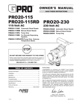
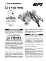
Kits and Accessories
133502-1 Vane Kit – O-Ring, 2 in. vanes, shaft key
133503-1 Shaft Seal Kit – Retaining ring, shaft seal,
spacer washer
133503-05 Shaft Seal Kit, Extreme Temperature Series
133504-1 Seal Kit
B
C
A
ILLUSTRATED PARTS DRAWING
121013-503 Check Valve Assembly Kit
504500-04 Spares, Base Assembly, 2" Inlet
504500-02 Kit, Switch, PRO35-115 / PRO95-230
504500-03 Vacuum Breaker Kit
1
2
3
4
5
16
6
7
8
34
910
12
15
13 23
14
33
22
17
23
18 19
D
28
36
34
25
24
35
31
32
30
29
Item
No. Part No. Description No. Req'd.
1 904006-38 Hex Head Screw 3
/
8 -16 x 1" ...................................2
2 133032-02 Coverplate ..............................................................1
3 901003-15 O-Ring (or Kit ) ...................................................1
4 121010-03 Shaft Key (or Kit ) ...............................................1
5 133041-1 Rotor .......................................................................1
6 904006-33 Retaining Ring (or Kit ) .......................................4
7 133027-1 Spacer Washer (or Kit ) ......................................1
8 906006-53 Shaft Seal (or Kit ) ..............................................1
9 904006-54 Socket Head Screw 3
/
8 -16 x 1"...............................3
10 133039-05 Housing ..................................................................1
11 133026-1 Slinger Washer .......................................................1
12 133521-01 Spares, Motor, ¾ HP, 115/230 V ............................1
13 13312401 Nozzle Cover ..........................................................1
14 13312301 Switch Lever ...........................................................1
15 904006-57 Spacer Washer .......................................................2
16 133042-1 Vanes (or Kit ) ....................................................8
Item
No. Part No. Description No. Req'd.
17 904006-49 Hex Head Screw 3
/
8 -16 x 3-¾" ...............................1
18 133033-1 Base End Plate .......................................................1
19 901001-90 O-Ring (or Kit ) ..................................................1
22 901002-89 O-Ring (or Kit ) ...................................................1
23 904001-37 Hex Head Screw 5
/
16 -18 x ¾" .................................4
24 133059-06 Poppet Plug ............................................................1
25 901002-50 O-Ring (or Kit ) ..................................................1
28 133141-01 Base .......................................................................1
29 133505-04 Poppet Assembly Kit...............................................1
30 906008-70 1" NPT Automatic Nozzle .......................................1
31 150100-01 Hose Assembly, 1" NPT x 1" x 18 ft. .......................1
32 906001-10 1" NPT Manual Nozzle ...........................................1
33 133419-02 Switch Locking Lever..............................................1
34 90400812 Plug, ¼" NPT ..........................................................3
35 90400823 Socket Head Screw 5
/
16-18 x 7
/
8" ............................4
36 133142-02 Tank Adapter, 2" NPT x ¼" NPT .............................1
GPRO™

7922108-01D PRO35-115 / PRO35-115RD
SPECIFICATIONS
The PRO35 series fuel pump is designed to safely trans-
fer low viscosity petroleum fuels such as gasoline (up to
15% alcohol blends such as E15), diesel fuel (up to 20%
biodiesel blends such as B20) and kerosene. The pump
is designed for permanent mounting on vented storage
tanks, either in-ground or above-ground. RAINPROOF
for outdoor use. Use of alcohol blends above 10% (E10)
and biodiesel blends above 5% (B5) have not been
reviewed by UL.
Performance
Pump Rate: Up to 35 GPM (132 LPM)
Duty Cycle: 30 minutes ON, 30 minutes OFF
Dry Prime: 15 ft. (4.6 m) maximum
Discharge Lift: 10 ft. (3 m) maximum
Operating Temperature
-20° F to +125° F (-29° C to +52° C)
XTS Operating Temperature
Extreme Temperature Series pumps are capable
of operation down to -40
°
F. Any pump operation
below -20
°
F has not been evaluated by UL.
Bypass Pressure
25 PSI
Electrical
Input: Factory set at 115 VAC, 60 Hz. Optional
to set at 230 VAC, 60 Hz.
Conduit: ½ in. FNPT
Current Draw: 9.8 amps at full load (at 115 VAC, 60
Hz)
Motor: ¾ HP, 1725 RPM induction type
provided with an internal auxiliary
temperature-limiting device
Mechanical Connections
Bung: 2 in. MNPT
Inlet: 1 ¼ in. FNPT
Outlet: 1 in. FNPT
Accessories
Hose: 1 in. NPT x 1 in. x 18 ft. (5.5m) Buna-N
electrically conductive
Nozzle: 1 in. NPT manual or 1 in. NPT auto-
matic diesel
Security: Nozzle can be padlocked
Ship Weight PRO35-115PO 67.0 lbs (30.4 kg)
PRO35-115MD 78.0 lbs (35.4 kg)
PRO35-115AD 80.2 lbs (36.4 kg)
PRO35-115RD 65.1 lbs (29.5 kg)
SAVE THESE INSTRUCTIONS
PARTS AND SERVICE
In order to preserve the UL Listing for pump safety, return
the entire pump to the factory for repair or replacement.
For products serviced outside the factory, the UL name-
plates must be defaced to indicate that the equipment
may no longer meet the requirements for UL Listing.
This does not apply to products serviced outside the
factory under the UL program for Rebuilt Motors for Use
in Hazardous Locations.
For warranty consideration, parts, or other service infor-
mation, please contact your local distributor. If you need
further assistance, contact the Great Plains Industries
Customer Service Department in Wichita, Kansas, during
normal business hours.
800-835-0113 or 316-686-7361
To obtain prompt, efcient service, always be prepared
with the following information:
1. The model number of your pump.
2. The manufacturing date code of your pump.
For the PRO35 series, the date code is located on the
motor nameplate.
For warranty work, always be prepared with your original
sales slip or other evidence of purchase date.
Please contact Great Plains Industries before returning
any pump. It may be possible to diagnose the trouble
and nd a solution with a telephone call. Great Plains
Industries can also inform you of any special requirements
you will need to follow for shipping.
Do not return the pump without authority from the Customer
Service Department. Due to strict government regulations, Great
Plains Industries cannot accept pumps unless they have been
drained and cleaned.
CAUTION
POWER OPERATED
PUMP FOR PETROLEUM
PRODUCTS
MOTOR FOR
HAZARDOUS LOCATIONS
Certied
Motor

922108-01D11/14
© 2014 Great Plains Industries, Inc. All Rights Reserved. Made in U.S.A. and GPROTM are trademarks,
and the electric gear pump design is a registered trademark of Great Plains Industries, Inc.
/