Page is loading ...

PRE-INSTALLATION GUIDE
DENTAL AIR SYSTEM
with Membrane Dryer
All Installations must conform to local codes!
This AirStar Model is being installed:
(AS CHECKED)
AS10 AS12 AS21 AS22
AS30 AS40 AS50 AS70 AS100
Doctor: __________________________________________________
Address: __________________________________________________
Phone#: __________________________________________________
Dealer: __________________________________________________
Dealer Address: __________________________________________________

Air System Plumbing Connection
- 3/8" FNPT Shut-off valve and a 6 ft. pressure hose (supplied)
- Air distribution piping for all models - 1/2", type "L" or type "K" copper
- If pipe volume is too great, more than 235 in3 or more than 100 ft. of 1/2"
diameter pipe, a pressure regulator should be installed between the main
tank and the distribution piping and set to 80 psi.
Service Clearance
- Allow 12" on all sides for all units
Ambient Temperature
- Must not exceed 105°F
- Must be above 41° F
Remote Air Intake Kits:
Model AS10 AS12 AS21 AS22 AS30 AS40 AS50 AS70 AS100
Part No. 85491 85491 85492 85492 85492 87361 85493 85494 85511
Air Techniques, Inc.
1295 Walt Whitman Road
Melville, New York, USA 11747- 3062
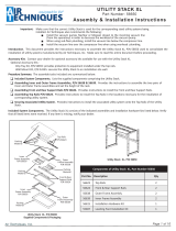
Equipment Room Layout
3/8” FNPT End fitting
1/2” Copper Main Air Line
Rear Clearance
12 inches minimum from wall
Maximum 24 inches from
main air line
Membrane Dryer Drain Valve
See Note 4
Notes:
1. Remote Air Intake Kit Manifold - Refer to the table below
listing the kit part number corresponding to the AirStar
model.
2. Remote Air Intake Drip Leg & Valve - A drip leg with drain
valve must be installed at lower end of the remote air intake
pipe to collect condensation during operation. Attach a drain
tube to the drip leg valve to allow drainage into oor drain/sink.
3. Air Pipe - Pipe can draw air from Inside or Outside. Drawing
air from cooler and drier environments is benecial to system
performance. If drawing from Inside, the pipe end should still
be protected from ingress of water and animals as appropriate.
Be aware that noise can emit from the pipe during compressor
operation; place end accordingly.
4. Membrane Dryer Drain Valve - Install the Drain Tube found
in either accessory kit P/N 87133 or P/N 87134 used to drain
moisture collected in the Membrane Dryer.
Control Cable 18 Gauge
4 Conductor Connect to
Pressure Switch.
See 24 Volt Circuit
Connections.
Remote 24 Volt Switch with
Pilot Light (sold separately)
Side Clearance
12 inches
36” max
2” Pipe & flexible
hose for Air Intake
supplied with Remote
Air Intake Manifold Kit.
13” max
Remote Air
Intake Manifold
(See Note 1 & Detail)
Air
Intake
Drip Leg
See Note 2
1
4
3
2
Air Intake Manifold Detail
Apply Teflon Tape to
Threads and Screw
Fitting Into Filter
Kit includes 70” of clear PVC
Tubing per Number of Cylinders
AIR PIPE
2-Inch Pipe for Air Intake.
Must be protected from rain
and animals See note 3.
Shroud &
Screen
Screen Shroud &
Screen
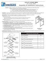
Building Power
Supply Panel
Buck/Boost
Transformer
(optional)
Type Style
AS10 5-20R
NEMA*
AS21
AS12
6-20R
NEMA*
AS22
AS30
AS40
AS50 Hard
Wired**
See Figure 3
for Connection
Details.
AS70
AS100
Green
Dot
Green
Dot
* Use Hospital Grade Receptacle Only
** Only AS100 Models use 3-Phase Power.
Disconnect Needed when Servicing.
36” max distance between
intake pipe & compressor
MEDICAL ELECTRICAL EQUIPMENT
WITH RESPECT TO ELECTRICAL SHOCK, FIRE, MECHANICAL AND OTHER SPECIFIED
HAZARDS ONLY IN ACCORDANCE WITH ANSI/AAMI ES60601-1: A1:2012, C1:2009/(R)2012
and A2:2010/(R)2012, CSA CAN/CSA-C22.2 NO.60601.14

AS10 AS12 AS21 AS22 AS30 AS40 AS50 AS70 AS100
Note 1: Install a buck or boost transformer if actual facility service is above or below the supply voltage fluctuation of ±10% of nominal voltage
ratings listed, install a buck/boost transformer with the corresponding part number as shown below.
Nominal Supply Voltage (VAC, see note) 120 220 120 220 220 220 220 220 3~220
Maximum Current (Amps) 8 4 15 8 8 12 16 24 20
Minimum Panel Breaker Rating (Amps) 20 10 20 20 20 20 20 40 30
Minimum Wire Size (AWG) 12 16 12 12 12 12 12 8 10
Maximum Watts 864 792 1,620 1,584 1,584 2,376 3,168 4,752 3,960
BTU/hr @ 50% 1,473 1,350 2,201 2,701 2,701 4,051 5,401 8,201 6,752
BTU/hr @ 75% 2,210 2,026 4,143 4,051 4,051 6,077 8,102 12,153 N/A
Note 2: The 220 volt 3-phase, 4.6 KVa transformer is not available from Air Techniques.
Buck/Boost Transformer Air
Techniques Part No. and Size
67006
2.5 KVa
67002
3.9 KVa
67006
2.5 KVa
67002
3.9 KVa
67002
3.9 KVa
67002
3.9 KVa
67002
3.9 KVa
67000-1
7.8 KVa
4.6 KVa
N/A
Site Requirements
All AirStar compressors comply with NFPA 99C level 3 requirements
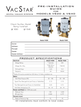
Electrical Connections
AS50 and AS70 Electrical Connections
L1
L2
GND
WHITE
GREEN
BLACK
WHITE
BLACK
GREEN
HARD WIRED
CONNECTED
AIRSTAR MODELS
AS50 & AS70
AS100 3-Phase Electrical Connections
BLUE
L1
L2
GND
L3
GREEN
BLACK
RED
RED
BLACK
BLUE
GREEN
HARD WIRED
CONNECTED
AIRSTAR MODEL
AS100
24V Circuit
Connections
AirStar Electrical Connection
Interconnect
Cable
Yellow 2
Brown 4
Orange 3
See Note 3
Future Use
Remote Panel
Yellow 2
Brown 4
Orange 3
White
White
See
Note 4
Connection
without
24V Switch
4 BRN
3 ORG
2 YEL
Notes:
1. Use 18 Gauge, 4 conductor, interconnect cable between the
AirStar unit and Remote Switch Panel.
When any 24V circuit exceeds 150 feet, use #16 AWG.
2. As shown, 3 conductors of the 24V circuit cable from each compressor
connect via the user-supplied interconnect cable.
3. The fourth conductor of interconnect cable to be used for future
equipment options/enhancements.
4. Leave with factory connection, without a 24V Switch, or connect
the associated interconnect cable directly to remote switch.
Please note that one switch is used for each compressor.
Pressure Switch
From
Electrical Box
2
4
3ORN
YEL
BRN
BLU
BLK
BRN
YEL
BLK
BRN
BLU
ORN
To Remote
Panel
YEL
ORN ORN
YEL

AirStar is a trademark of Air Techniques, Inc. 2009 Air Techniques, Inc. • PN 87104 Rev. P May 2021
www.airtechniques.com
Corporate Headquarters
1295 Walt Whitman Road Melville, New York 11747- 3062
Phone: 800-247-8324 Fax: 888-247-8481
Product Specifications - Dimensions
AS10 AS12 AS21 AS22 AS30 AS40 AS50 AS70 AS100
Input Voltage Phase 11111 1 1 13
System Power
HP
(kW)
0.75
(0.56)
0.75
(0.56)
1.5
(1.1)
1.5
(1.1)
1.5
(1.1)
2.25
(1.68)
3.0
(2.2)
4.5
(3.4)
4.8
(3.6)
Nominal Supply Voltage VAC 120 220 120 220 220 220 220 220 220
Frequency Hz 60 60 60 60 60 60 60 60 60
Maximum Current Amps 8 4 15 8 8 12 16 24 20
Maximum Simultaneous Air
Users 2 2 3 3 4 6 8 12 15
System Output Flow Rate at
80 PSI CFM 2.5 2.5 5.0 5.0 5.0 7.5 10.0 15.0 20.0
Maximum Pump-up Time
0-115 PSI (M:SS) 2:55 2:55 3:10 3:10 3:10 1:40 2:50 2:40 2:30
Maximum Recovery Time
85-115 PSI (M:SS) 0:48 0:48 0:47 0:47 0:47 0:34 0:42 0:40 0:30
Tank Size
US Gal.
(ft3)
6
(0.8)
6
(0.8)
12
(1.6)
12
(1.6)
12
(1.6)
12
(1.6)
20
(2.7)
30
(4.0)
30
(4.0)
Shipping Weight lbs.
(Approximate)
No Sound Cover
With Sound Cover
170
215
170
215
200
240
200
240
240
285
255
300
290
335
430
N/A
450
N/A
Dimensions in.
(See note.)
No Sound Cover
H
W
D
28.50
25.00
19.75
28.50
25.00
19.75
30.50
29.00
20.00
30.50
29.00
20.00
30.50
29.00
20.00
30.50
32.50
20.00
33.50
35.50
20.50
35.00
47.75
21.75
34.50
46.00
24.50
With Sound Cover
H
W
D
30.00
25.00
22.50
30.00
25.00
22.50
32.00
31.00
22.25
32.00
31.00
22.25
32.00
31.00
22.25
32.25
33.25
22.50
33.50
36.50
22.75
36.00
51.00
29.50
N/A
N/A
N/A
Description
Model
Note: Height measured without leveling feet for all units with or without sound cover.
/