Page is loading ...

HCC 260 P1 - HCC 360 P2 - HCC 360 E1
SERVICE MANUAL
en • Rev. 1.0 • 2020-45-3

3
Introduction: Table of contents
en
Introduction
Table of contents
This service manual covers the following main topics:
Table of contents
Introduction .....................................................................3
Table of contents ......................................................................3
Overview .............................................................................4
Declaration of conformity .............................................................5
Product description ..............................................................6
Overall description ....................................................................6
Components description ..............................................................9
Accessory . . . . . . . . . . . . . . . . . . . . . . . . . . . . . . . . . . . . . . . . . . . . . . . . . . . . . . . . . . . . . . . . . . . . . . . . . . . . 10
System operation strategy. . . . . . . . . . . . . . . . . . . . . . . . . . . . . . . . . . . . . . . . . . . . . . . . . . . . . . . . . . . . 11
Installation .................................................................... 12
General location requirements. . . . . . . . . . . . . . . . . . . . . . . . . . . . . . . . . . . . . . . . . . . . . . . . . . . . . . . . 12
Installation options. . . . . . . . . . . . . . . . . . . . . . . . . . . . . . . . . . . . . . . . . . . . . . . . . . . . . . . . . . . . . . . . . . . 14
Mounting . . . . . . . . . . . . . . . . . . . . . . . . . . . . . . . . . . . . . . . . . . . . . . . . . . . . . . . . . . . . . . . . . . . . . . . . . . . . 17
Connecting additional equipment ....................................................21
Initial calibration .....................................................................24
Operation (user) ................................................................ 26
Overall ventilation functions .........................................................26
User Rights. . . . . . . . . . . . . . . . . . . . . . . . . . . . . . . . . . . . . . . . . . . . . . . . . . . . . . . . . . . . . . . . . . . . . . . . . . . 27
Maintenance and care .......................................................... 28
Preventative maintenance . . . . . . . . . . . . . . . . . . . . . . . . . . . . . . . . . . . . . . . . . . . . . . . . . . . . . . . . . . . . 28
Trouble shooting .....................................................................31
Appendix ...................................................................... 38
Technical data. . . . . . . . . . . . . . . . . . . . . . . . . . . . . . . . . . . . . . . . . . . . . . . . . . . . . . . . . . . . . . . . . . . . . . . . 38
Schematics. . . . . . . . . . . . . . . . . . . . . . . . . . . . . . . . . . . . . . . . . . . . . . . . . . . . . . . . . . . . . . . . . . . . . . . . . . . 40
Week program specication ..........................................................41
Spare parts. . . . . . . . . . . . . . . . . . . . . . . . . . . . . . . . . . . . . . . . . . . . . . . . . . . . . . . . . . . . . . . . . . . . . . . . . . . 43

4
Introduction: Overview
Overview
This is the service manual for the Dantherm HCC 260/360 residential ventilation unit.
Part number of this service manual is 108478 and covers units with serial numbers from:
HCC260 P1-A-BP - 2010121652545
HCC360 E1-A-BP-RH - 2010131652548
HCC360 P2-A-BP-RH - 2010131652549
This manual is for both installers and users of the product.
Installation and repair of the unit is to be carried out by qualied personnel only. It is the
responsibility of the installer to read and understand this service manual prior to initial start
and setup of the HCC 260/360 unit. Warranty is restricted to units, installed by trained person-
nel only.
This application is not intended for use by persons (including children) with reduced physi-
cal, sensory or mental capabilities, unless they have been given supervision or instructions
concerning the use of the appliance by a person responsible for their safety.
Children should be supervised to ensure that they do not play with the appliance.
Apart from the replacement of air lters and exterior cleaning of the system, any kind of
maintenance will require the use of trained personnel.
The unit MUST be earthed, through cables WITH earth wire and earthed power supply.
Copying of this service manual, or part of it, is forbidden without prior written permission
from Dantherm
Dantherm reserves the right to make changes and improvements to the product and the
service manual at any time without prior notice or obligation.
This units is designed for long term durability. When total lifetime ends, the unit should be
recycled according to national rules and with high environmental protection considerations
This manual uses following abbreviations for ventilation terminologies.
Abbr. Description
T1 Outside air coming into the unit
T2 Supply air from the unit to the home
T3 Extract air from the home to the unit
T4 Exhaust air from the unit
S1 Temperature sensor no 1
S2 Temperature sensor no 2
S3 Temperature sensor no 3
S4 Temperature sensor no 4
Mode A Indicating operation mode A. See more at page 15
Mode B Indicating operation mode B.(reverse fan) See more at page 15
G4 Standard air lter class (ISO Coarse)
F7 Filter class (ePM1), better and absorbs ner grains than G4 lter
BP Bypass damper
IP Unique address for the Ethernet port.
DHCP Automatic settings of an Ethernet address provided from an external network
component ( if connecting the unit to Ethernet)
PC Personel computer running MS Windows
USB Universal serial bus connection– located on almost any computer
LAN Local area network is the internal network with or without wireless access
VOC Volatile organic compounds sensor, controls the ventilation level depending on
the pollution of the air.
PC Tool Windows software application specic for this unit.
Manual
Target group
Warning
Caution
WARNING
Warning
Caution
WARNING
Copyright
Reservations
Recycling
Abbreviations in
this manual

5
Introduction: Declaration of conformity
en
Declaration of conformity
Dantherm hereby, declare that the unit mentioned below:
No.: 352444 Type: HCC 260/360
- complies with the following directives:
2014/35/EU Low Voltage Directive
2014/30/EU EMC Directive
2014/53/EU RED
2009/125/EC Eco Design Directive (incl. Regulation 2014/1253)
2011/65/EU RoHS Directive
1907/2006/EC REACH Regulation
- and is manufactured in compliance with the following standards:
EN 60335-1:2012 Household and similar electrical appliances - Safety - Part 1
EN 60335-2-40:2003 Household and similar electrical appliances - Safety - Part 2-40
EN 61000-3-2:2014 Electromagnetic compatibility (EMC) - Part 3-2
EN 61000-3-3:2013 Electromagnetic compatibility (EMC) - Part 3-3
EN 61000-6-2:2005 Electromagnetic compatibility (EMC) - Part 6-2
EN 61000-6-3:2007 Electromagnetic compatibility (EMC) - Part 6-3
EN 60730-1:2011 Automatic electrical controls for household and similar use - Part 1
EN 62233:2008 Measurement methods for electromagnetic elds of household
appliances
EN 55014-1:2006 Electromagnetic compatibility - Requirements for household
appliances - Part 1
EN 55014-2:1997 Electromagnetic compatibility - Requirements for household
appliances - Part 2
EN 301 489-1 V1.9.2 ElectroMagnetic Compatibility (EMC) standard for radio equipment
and services; Part 1
EN 301489-3 V1.6.1 ElectroMagnetic Compatibility (EMC) standard for radio equipment
and services; Part 3
EN 300 220-1 V2.4.1 ElectroMagnetic compatibility & Radio spectrum Matters (ERM);
Short Range Devices
EN 300 220-2 V3.1.1 ElectroMagnetic compatibility & Radio spectrum Matters (ERM);
Short Range Devices
EN 13141-7:2010 Ventilation for buildings - performance testing of components/
products for residential ventilation
Skive, 24.09.2020
Declaration of
Conformity

6
Product description: Overall description
Product description
Overall description
HCC 260/360 residential ventilation unit is designed to supply fresh air to residential home, by
exchanging heat from outgoing air to incoming air, resulting in low heat energy loss.
These units are designed for installation underneath a ceiling, in dry surroundings, with tem-
peratures >12°C. e.g. utility room or similar heated rooms.
The duct connections can be electronically swapped, providing ability to route the connected
ducts, either to the right or to the left, as described on page 15
This illustrates the unit, without the steel drip tray:
1
13 14 15
2356
7
9
811
12
10
4
Fig. 1
This table shows the parts according above illustration:
Pos Mode A(default) Mode B
1 Extract lter ISO Coarse Supply lter ISO Coarse or ePM1
2 Bypass module
3 USB connection
4 Filter reset button
5 Controller PCB (external connections see page 21)
6 Supply lter ISO Coarse or ePM1 Extract lter ISO Coarse
7 Extract air - T3 Outside air - T1
8 Blocked Water drainage spigot
9 Supply air - T2 Exhaust air-T4
10 Outside air - T1 Extract air - T3
11 Water drainage spigot Blocked
12 Exhaust air – T4 Supply air - T2
13 Supply fan Extract fan
14 Heat exchanger
15 Extract fan Supply fan
Introduction
Product illustration
Part description

7
Product description: Overall description
en
There are three dierent variants of the HCC 260/360 unit: P1, P2, E1. The function and instal-
lation of the unit is exactly the same.
The variants only dier by either heat exchanger or ventilator thus inuencing the perfor-
mance of the unit.
The product label showing the variant is placed on the cover for PCB access beside the lter
reset button (see g. 2).
Fig. 2
This illustration shows the air ow paths, through the unit.
See more about changing operation mode at page 16
Fig. 3
HCC 260/360
variants
P1, P2, E1
Airows

8
Product description: Overall description
This illustration shows correct placement of sensors (if available) are placed inside the unit.
See also “Part description” on page 6
Sensor 1Sensor 3 Mode A
RH% / VOC
Mode B
RH% / VOC
Sensor 2 Sensor 4
Fig. 4
Sensor function according operation mode:
Sensor Mode A Mode B
1 Outside air - T1 Extract air - T3
2 Supply air - T2 Exhaust air-T4
3 Extract air - T3 Outside air - T1
4 Exhaust air – T4 Supply air - T2
Sensor placement

9
Product description: Components description
en
Components description
This section describes the individual components which are included in the HCC 260/360
unit. Please use the illustration on page 6 for reference.
Cabinet outer parts are made of aluzink sheet metal. The inner part is one moulded polysty-
rene block. If adding accessory or exchanging parts, access to all parts are available, just by
removing the front cover and drip tray.
The cabinet is internal sound and heat insulated, with re retardant polystyrene foam. The
unit´s cabinet is designed for mounting in 12°-40° C ambient temperature
The counter ow heat exchanger absorbs the heat energy from extract air and moves this
heat energy to the ingoing supply air, resulting in domestic ventilation with low heat loss.
The supply fan supplies fresh outdoor air through the unit’s heat exchanger to the ducts,
where it´s distributed to bedrooms, living rooms and possibly sauna or steam bath.
The extract air fan draws used, moistened and polluted air from house, through the unit and
heat exchanger, where the heat is transferred to supply air.
The motorized bypass damper overrides the heat exchanger functionality. This is used in
warm summer conditions, where colder outside air can be used for reducing inside tempera-
ture, when inside temperature exceeds an upper temperature limit.
The unit´s main controller is named main PCB. It electrically connects all electrical and elec-
tronic parts and various accessory components.
Units are tted with 4 temperature sensors that continuously monitor the temperature
changes on 4 sides of heat exchanger, i.e. in outdoor air, in supply air, in extract air and in
exhaust air.
The HCC 260 P1 unit, is not default tted with a RH sensor. RH sensor is available as an acces-
sory.
HCC 360 P2 and E1 units are tted with an RH sensor in the extract duct.
The humidity sensor will continuously monitor the quality of the extract air, and adjust the air
ow level accordingly. This operation is named demand mode.
If an HRC remote control is connected, the level will be shown in the display using 3 level
icon.
Using demand mode will result in the correct level of ventilation with lowest possible electri-
cal power consumption.
The unit is tted with two ISO Coarse class cassette lters. These lters protect the heat ex-
changer and improve the indoor climate by removing dust and particles in both airows.
As alternative/accessory, an ePM1 class lter can be obtained. If ePM1 is used, then it is always
placed in the supply air, removing even smaller particles.
The unit is tted with 2 pcs. spigot connections for draining condensed water. It is manda-
tory to t the spigot next to the T4 with a hose, discharging the condensed water to a sever.
Correct drainage is shown on the connection label placed on the unit. The remaining un-
used drain is to be blocked with the enclosed cap.
The unit is delivered with hanging rail.
Introduction
Cabinet
Heat exchanger
Fans
Bypass damper
Controller
Temperature sensor
Humidity sensor
Filters
Water drainage
Hanging rail

10
Product description: Accessory
Accessory
The unit is delivered from factory, without any accessories mounted. These are to be installed
prior to initial unit installation or alternative after commissioning, if further functionality is
requested. The detailed installation of one or more accessories, is illustrated on the leaet fol-
lowing each accessory .
The unit can be tted with an electrical preheating element that preheats the incoming air.
The preheater increases the outside air temperature going into the heat exchanger, and
thereby reduces the risk of ice in the heat exchanger in very cold conditions.
The preheater is an external enclosure, connected and controlled by the HCC 260/360 con-
troller.
For controlling HCC 260/360
units, Dantherm recommends us-
ing remote control, designed for
this range of units.
CO2
RH%
°
°
°
°
AUTO
*
*
*
*
*
Ikoner for manual
A wired remote control (HCP 10/11) without display can be
connected to the unit as an alternative to the hand held remote
control.
Connect a number of additional accessories to the
HCC 260/360 unit via an accessory controller: HAC 2.
HCC 260/360 can be tted with Humidity (RH%) (if not al-
ready included as standard) and/or VOC (organic chemi-
cals) sensors. These sensors will continuously monitor
the extract air, and adjust the air ow level accordingly.
This will result in adequate level of ventilation, with low-
est possible electrical power consumption. If a remote
control is connected, the sensor level will be shown in
the display using 3 level icon.
Replacement of lters in sets of 2 ISO Coarse lters or 1 ISO Coarse plus 1 ePM1 (pollen) lter.
Introduction
Electric preheating
Hand held Remote
control
Fig. 5
Wired Remote
Control
(HCP 10/11)
Fig. 6
Accessory control
(HAC 2)
Fig. 7
VOC and humidity
sensors
Fig. 8
RH% VOC
Filters

11
Product description: System operation strategy
en
System operation strategy
This section describes the operation strategy in various conditions. For a user specic running
operation see page 26.
In cold conditions where T1 is below -4°C and exhaust T4 is <+8°C the condensed water could
built up as ice in the heat exchanger, blocking the air path and eventually destroying the heat
exchanger.
In order to prevent this sequence is initiated:
• The supply fan speed will decrease with 3 rpm/second until minimum RPM is reached.
• After 10 seconds at this speed the supply fan will stop completely, while the ongoing
exhaust fan is supplying warmer air into the heat exchanger component, to remove any
potential ice.
• When T4 yet again is >+8°C the supply fan will start at minimum RPM, and then increase
speed with 3 rpm/second until the original required speed is regained.
• If T4 becomes <+2°C during the speed increase cycle, the supply fan will decrease speed
again.
• If T1<= -13°C for more than 4 minutes and 25 seconds, even with defrost mode active, the
unit will stop all operation for 30 minutes, and reattempt previous operation condition. If
electrical preheat is present, this total o mode is disabled.
The defrost operation will create an under pressure inside the house, so if replace mode is
enabled, and defrost is necessary; the unit will stop all operation in 4 hours instead. Set-
points cannot be changed.
When defrost is active any connected remote control will showin the display, and
when defrost has shut all o, the display will ash the T1 temperature
If the preheater is installed, the unit will add electrical heat to the incoming outdoor air, in
order to increase the temperature of outdoor air entering the heat exchanger and thereby
reduce or eliminate the possibility of going into defrost mode and to ensure balanced opera-
tion as long as possible.
• Preheater can be “master” enabled/disabled on the wireless remote control in installer
mode
• Preheat is applied before the T1 sensor.
• If outside temperature is <-3°C or supply air is < 16,5°C the preheater will switch on with
10% power.
• The power will increase/decrease 10% for each 60 seconds depending on the T1 or T2
temperature.
Temperature set-points are xed.
Introduction
Defrost
Preheat
(Accessory)

12
Installation : General location requirements
Installation
General location requirements
The HCC 260/360 must full all of the previous consideration prior to starting any installation
process.
The following should be considered selecting an appropriate location for installation:
1. The HCC 260/360 units, is designed to be mounted in dry surroundings, with tempera-
tures >12°C like in utility rooms or similar heated rooms.
2. The HCC 260/360 can be mounted vertically or horizontally. Please ensure that the ceiling
or walls structure is adequate to withstand the additional weight of the unit.
3. The air ow direction can be electronically swapped, providing ability to route the con-
nected ducts, either to the right or to the left. See more about swapping at page 16.
4. It is mandatory to tilt the HCC 260/360 minimum 1° towards the drain. The enclosed
bracket provides this requirement, in case of horizontal ceiling.
The HCC 260/360 is designed for hidden installation.
It is very important to leave additional space:
• Adequate space for exchanging the unit if needed, including turning the unit into its
bracket and up, if mounting underneath the ceiling.
• External preheater (accessory), which is mounted external into the duct system on the T1
incoming outside air, minimum 320 mm from the unit.
• Additional space, in order to inspect and test any drainage hose, also if no preheater is
installed..
This applies also for after sales situations, where the unit is to be dismounted completely for
service. Any warranty claim will not be acknowledge if these above requirements are not
fullled.
See min. measurements on page 13.
If installing the unit underneath the ceiling, please reserve space for the tilting up/down, and
additional space, if electrical preheater is installed.
Additional space dimensions here shown in operation mode A
1122
620
320
80
1 2
Fig. 9
Introduction
Location and duct
connections
Reserve additional
space
Service space,
ceiling

13
Installation : General location requirements
en
and here shown in operation mode B
1122
80
320
620
12
Fig. 10
No Description
1 This space is mandatory in order to lift the unit upwards in its wall bracket. Please AL-
WAYS mount the bracket and reserve this space, at the unit end, in which the T1 and
T4 (cold ducts) are connected. If preheater is installed, this additional space is require
to make future service if needed.
2 In order to be able to mount the screws into the ceiling properly, please add mini-
mum this space shown
If installing the unit onto the wall, always have the T1 and T4 (cold ducts) in the bottom of the
unit. If the unit has additional preheater, please allow space for this as well, see illustration.
1122
620
110
70
550
Pre-heater space
Fig. 11
Service space, wall

14
Installation : Installation options
Installation options
HCC 260/360 has a variety of installation options such as vertical or horizontal mounting,
exible cable routing and duct connections making the unit adaptable to dierent locations.
Check the installation options and decide how the installation best fulls the local demands.
Please ensure that the ceiling or walls structure is adequate to withstand the additional
weight of the unit.
Remember to reserve the mandatory service space.
All cable connection can be routed inside the unit, for exit through both end plates (g. A).
Alternatively connect as shown in g. B. This enables the installer to route and connect cables
in best suitable way.
Option 1 Option 2
Introduction
Vertical or
horizontal
Fig. 12 Fig. 13
!NOTICE
Cable routing
The drain hose must not be down in the oor drain
B
A
A

15
Installation : Installation options
en
The air ducts going into the house can either be connected on the right hand side or the left
hand side. The default mode is mode A. (Follow procedure on page 16 for swapping to
mode B)
Illustration of duct connections in operation mode A:
Fig. 14
Illustration of duct connections in operation mode B:
Fig. 15
Selecting
mode A or B

16
Installation : Installation options
Always disconnect the power by removing the 230V plug from the socket, before opening
the unit !
If local systems demand mode B, follow the below procedure AND check the label in order to
connect the water drainage correctly.
Step Action Illustration
1Locate the small lid on the long
side of the unit closest to the lter
lids.
2Locate the switch on the main PCB
The default is mode A as shown. To
select mode B slide the switch to
the right. Close the lid again.
3Swap the drain hose and plug as
indicated.
For a further description of the
drain hose installation, see page
20.
Mode A
Mode B
4 To swap the RH sensors, open
sidepanel and look for the marking
“A” and “B”
Mode A Mode B
5Swap the lter (ONLY if the option-
al pollen lter ePM1 is used for the
supply air).
• Check the table on page 6
in order to determine the right
position of the ePM1 lter during
mode A/B.
6Place new B sticker and calibration sticker on the unit.
7Connect the duct as specied on the label and described on page 19.
8Calibrate the unit as described on page 24.
Warning
Caution
WARNING
Swapping to
mode B
A B

17
Installation : Mounting
en
Mounting
The enclosed bracket can and should be used, both for wall and for ceiling installation. The
bracket will automatically tilt the unit 1° towards the condensate drain, when mounted un-
derneath the ceiling (g. 16) and when maounted on the wall (g. 17).
Please follow this procedure to install the HCC 260/360 vertical onto a wall.
Step Action Illustration
1
Drill two holes for the
bracket, fullling all dimen-
sion requirements shown in
the section “General location
requirements” on page 12.
8 mm
4 mm
3 mm
8 mm
4 mm
3 mm
2Mount the bracket with ap-
propriate screws
3 Lift the unit onto the bracket
4
Drill and mount two appro-
priate screws in the lower
unit bracket
5
Connect ducts according il-
lustration at page 15
IMPORTANT: the T1 and T4
outside air ducts, must AL-
WAYS be routed to the duct
connections in the bottom
6Connect ducts and drain
hose.
Multi purpose
mounting bracket
Fig. 16 Fig. 17
Wall mounting
2
4
1

18
Installation : Mounting
Please follow this below procedure for ceiling installation
Step Action Illustration
1 The HCC 260/360 should
always tilt minimum 1°
towards the drain side(T4).
This is achieved when us-
ing the enclosed bracket,
placed at T4 end of unit.
Drill two holes and mount
the bracket into the ceiling
conguration setup (see
page 17)
Please allow minimum 320
mm to the ceiling edge,
in order to have room for
turning the unit in step 2.
8 mm
4 mm
3 mm
320 mm
2 Lift the unit onto the
bracket hanging freely as
shown
8 mm
4 mm
3 mm
3 Turn the unit towards the
ceiling, and secure it with
two screws
8 mm
4 mm
3 mm
4 Connect ducts and drain hose.
Under ceiling
installation

19
Installation : Mounting
en
Connect ducts (specication according local regulations), with spigot connection only.
WARNING: NEVER screw any spigot for ducts, directly onto the sheet metal of the unit.
Fig. 18
Insulate the ducts according local requirements, taking the installation surrounding tempera-
ture into consideration.
Make sure that all ducts are well attached and secure, and ALWAYS xed securely to the ceil-
ing or wall with brackets
Bracket Bracket
Fig. 19
Connect duct
system
Secure ducts

20
Installation : Mounting
It is mandatory in any HCC 260/360 installation to connect a water drain hose to the unit,
because the humidity from the extract air condensates to water drops when cooled in the
heat exchanger.
This water is harmful to its surrounding if not managed correctly. The installation thus needs a
condensate water drain hose connected with a decline of minimum 10 Promille (1 cm/meter)
away from the unit and the hose must NEVER exceed the level of the lower sheet metal plate.
Faulty installation
The drain hose must never be raised above
the bottom plate!
Fig. 20
After guiding the hose downwards to a drain, it needs a closing loop. This will block air from
escaping through the hose. Please make either a complete closed loop, or a siphon loop on
the hose as illustrated, and make sure it has a minimum height of 100 mm. Fill the siphon/
loop with min. 0,5 l. water before connecting the hose to the unit.
or
100 mm
100 mm
Fig. 21
Drainage
consideration
Correct installation
The drain hose has a correct and steady fall
towards the sewer.
Condensate
drainage

21
Installation : Connecting additional equipment
en
Connecting additional equipment
Connecting additional equipment is to be carried out by qualied personnel only. Always
disconnect the power by removing the 230V plug from the socket, before opening the unit !
The integrated controller has various options to connect additional external equipment. To
gain access to the controller, please open the print cover (A) of the unit, by turning it all the
way around as shown in g. 22 .
Fig. 22
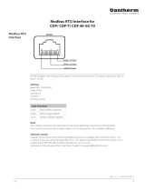
This illustration shows the various connections:
12 3 4
Fig. 23
Connection Description
1: ETHERNET LAN connection for connecting to wireless router for BMS and smart phone
app. functionality.
2: MODBUS Modbus connection for hardware accessory modul (HAC or HCP 10)
3: ANTENNA Wireless connection point for proprietary remote control.
4: DIG IN External digital input, to select specic operations. Parameters can be set in
the PC Tool.
Warning
Caution
WARNING
Access to
connections
External
connections options
A
/