Page is loading ...

Operating Instructions
Diesel engine
12 V 4000 M73 x
16 V 4000 M73 x
MS150045/02E

Engine model kW/cyl. Application group
12V4000M73 160 kW/cyl. 1B, continuous operation, variable, high load factors
12V4000M73L 180 kW/cyl. 1B, continuous operation, variable, high load factors
16V4000M73 160 kW/cyl. 1B, continuous operation, variable, high load factors
16V4000M73L 180 kW/cyl. 1B, continuous operation, variable, high load factors
Table 1: Applicability
Printed in Germany
© 2013 Copyright MTU Friedrichshafen GmbH
This Publication is protected by copyright and may not be used in any way whether in whole or in part without the prior
written permission of MTU Friedrichshafen GmbH. This restriction also applies to copyright, distribution, translation, mi-
crofilming and storage or processing on electronic systems including data bases and online services.
This handbook is provided for use by maintenance and operating personnel in order to avoid malfunctions or damage
during operation.
Subject to alterations and amendments.

Table of Contents
1 Safety
1.1 Important provisions for all products 6
1.2 Personnel and organizational requirements 7
1.3 Safety regulations for startup and operation 8
1.4 Safety regulations for maintenance and
repair work 9
1.5 Fire prevention and environmental
protection, fluids and lubricants, auxiliary
materials 12
1.6 Standards for safety notices in the text 14
1.7 Transport 15
2 General Information
2.1 Engine layout 16
2.2 Product description 17
2.3 Engine side and cylinder designations 26
2.4 Sensors and actuators – Overview 27
2.5 Engine wiring harness – Overview 37
3 Technical Data
3.1 12V 4000M73 engine data: EPA Tier 2,
engine-mounted heat exchanger, copper-
based alloy intercooler 44
3.2 12V 4000 M73 engine data: IMO, engine-
mounted heat exchanger, copper-based
alloy intercooler 47
3.3 12V 4000M73 engine data: IMO Tier II,
engine-mounted heat exchanger 50
3.4 12V 4000M73L engine data: IMO Tier II,
engine-mounted heat exchanger 53
3.5 12V 4000M73L engine data: IMO, engine-
mounted heat exchanger, copper-based
alloy intercooler 56
3.6 12V 4000M73L engine data: EPA Tier 2,
engine-mounted heat exchanger, copper-
based alloy intercooler 59
3.7 16V 4000M73 engine data: EPA Tier 2,
engine-mounted heat exchanger, copper-
based alloy intercooler 62
3.8 16V 4000M73 engine data: IMO, engine-
mounted heat exchanger, copper-based
alloy intercooler 65
3.9 16V 4000M73 engine data: IMO Tier II,
engine-mounted heat exchanger 68
3.10 16V 4000M73L engine data: IMO Tier II,
engine-mounted heat exchanger 71
3.11 16V 4000M73L engine data: IMO, engine-
mounted heat exchanger, copper-based
alloy intercooler 74
3.12 16V 4000M73L engine data: EPA Tier 2,
engine-mounted heat exchanger, copper-
based alloy intercooler 77
3.13 Engine – Main dimensions 80
3.14 Firing order 81
4 Operation
4.1 Operation 82
4.2 Putting the engine into operation after
extended out-of-service periods (>3 months) 83
4.3 Putting the engine into operation after
scheduled out-of-service-period 84
4.4 Starting the engine 85
4.5 Operational checks 86
4.6 Tasks after extended out-of-service periods
(>3 weeks) 87
4.7 Fuel treatment system control cabinet –
Control elements 88
4.8 Checks prior to start-up 89
4.9 Fuel treatment system – Putting into
operation 90
4.10 Fuel treatment system – Switching on 93
4.11 Engine – Stopping in manual mode (test
run) 94
4.12 Engine emergency stop at BlueLine
automation system (control stand) 95
4.13 Coupling – Engaging from LOP 96
4.14 Coupling – Disengaging from LOP 97
4.15 Waterjet – Flushing from LOP (optional) 98
4.16 Stopping the engine from LOP 99
4.17 Stopping the engine at the BlueLine
automation system (control stand) 100
4.18 Emergency stop from LOP 101
4.19 Stopping the engine 102
4.20 Emergency engine stop 103
4.21 After stopping the engine 104
4.22 Fuel treatment system – Shutdown 105
4.23 Plant – Cleaning 106
5 Maintenance
5.1 Maintenance task reference table [QL1] 107
6 Troubleshooting
6.1 Fuel treatment system – Troubleshooting 108
MS150045/02E 2013-07 | Table of Contents | 3
DCL-ID: 0000012062 - 003

6.2 Troubleshooting 109
6.3 ADEC (ECU 7) fault codes for Series 4000
engines, marine application 112
6.4 ADEC engine governor – Fault codes 113
7 Task Description
7.1 Engine 139
7.1.1 Engine – Barring manually 139
7.1.2 Engine – Barring with starting system 140
7.2 Cylinder Liner 141
7.2.1 Cylinder liner – Endoscopic examination 141
7.2.2 Instructions and comments on endoscopic and
visual examination of cylinder liners 143
7.3 Valve Drive 145
7.3.1 Valve gear – Lubrication 145
7.3.2 Valve clearance – Check and adjustment 146
7.3.3 Cylinder head cover – Removal and
installation 150
7.4 Injection Pump / HP Pump 151
7.4.1 HP pump – Filling with engine oil 151
7.5 Injection Valve / Injector 152
7.5.1 Injector – Replacement 152
7.5.2 Injector – Removal and installation 153
7.6 Fuel Filter 158
7.6.1 Fuel filter – Replacement 158
7.6.2 Fuel prefilter – Differential pressure gauge
check and adjustment 160
7.6.3 Fuel prefilter – Draining 161
7.6.4 Fuel prefilter – Flushing 163
7.6.5 Fuel prefilter – Filter element replacement 165
7.7 Exhaust Turbocharger 167
7.7.1 Compressor wheel – Cleaning 167
7.8 Charge-Air Cooling 171
7.8.1 Intercooler – Check water drain for coolant
discharge and obstruction 171
7.9 Air Filter 172
7.9.1 Air filter – Replacement 172
7.9.2 Air filter – Removal and installation 173
7.10 Air Intake 174
7.10.1 Service indicator – Signal ring position check
(optional) 174
7.10.2 Air pipework from air filter to ETC – Check 175
7.11 Starting Equipment 176
7.11.1 Starter – Condition check 176
7.12 Lube Oil System, Lube Oil Circuit 177
7.12.1 Engine oil – Level check 177
7.12.2 Engine oil – Change 178
7.12.3 Engine oil – Sample extraction and analysis 180
7.12.4 Engine oil – Sample extraction and analysis 182
7.13 Oil Filtration / Cooling 183
7.13.1 Automatic oil filter – Oil filter candles
replacement 183
7.13.2 Oil indicator filter – Cleaning and check 186
7.13.3 Centrifugal oil filter – Cleaning and filter-
sleeve replacement 188
7.14 Coolant System, General, High-Temperature
Circuit 190
7.14.1 Venting points 190
7.14.2 Engine coolant – Level check 191
7.14.3 Engine coolant – Change 192
7.14.4 Engine coolant draining 193
7.14.5 Engine coolant– Filling up 194
7.14.6 Engine coolant pump – Relief bore check 198
7.14.7 Engine coolant – Sample extraction and
analysis 199
7.15 Raw Water Pump with Connections 200
7.15.1 Raw water pump – Relief bore check 200
7.16 Battery-Charging Generator 201
7.16.1 Battery-charging generator drive – Coupling
condition check 201
7.17 Engine Mounting / Support 202
7.17.1 Engine mounting – Check 202
7.18 Auxiliary PTO 203
7.18.1 Bilge pump – Relief bore check 203
7.19 Fuel Supply System 204
7.19.1 Water drain valve – Check 204
7.19.2 Differential pressure gauge – Check 205
7.19.3 Water level probe (3-in-1 rod electrode) –
Check 206
7.19.4 Pump capacity – Check 207
7.19.5 Coalescer filter element – Replacement 208
7.20 Wiring (General) for Engine/Gearbox/Unit 210
7.20.1 Engine wiring – Check 210
7.21 Accessories for (Electronic) Engine
Governor / Control System 211
7.21.1 Limit switch for start interlock ‒ Check 211
7.21.2 Engine Control Unit ECU 7 – Checking plug
connections 212
7.21.3 Engine Monitoring Unit EMU 8 – Plug
connections check 213
7.21.4 Interface module plug connections – Check 214
7.21.5 ECU 7 engine governor – Removal and
installation 215
7.21.6 EMU 8 – Removal and installation 216
7.21.7 Engine Interface Module EIM – Removal and
installation 217
7.21.8 Diagnostic features of EIM 218
7.22 Emergency Instrumentation (Local
Operating Panel) 221
7.22.1 LOP and connectors – Cleaning 221
4 | Table of Contents | MS150045/02E 2013-07
DCL-ID: 0000012062 - 003

8 Appendix A
8.1 Abbreviations 222
8.2 MTU contact persons/service partners 224
9 Appendix B
9.1 Special Tools 225
9.2 Index 231
MS150045/02E 2013-07 | Table of Contents | 5
DCL-ID: 0000012062 - 003

1 Safety
1.1 Important provisions for all products
Nameplate
The product is identified by nameplate, model designation or serial number and must match with the
information on the title page of this manual.
Nameplate, model designation or serial number can be found on the product.
General information
This product may pose a risk of injury or damage in the following cases:
• Incorrect use
• Operation, maintenance and repair by unqualified personnel
• Modifications or conversions
• Noncompliance with the safety instructions and warning notices
Correct use
The product is intended exclusively for the application specified in the contract or defined at the time of
delivery.
This means that the equipment must be operated:
• Within the permissible operating parameters in accordance with the (→ product data)
• With fluids and lubricants approved by the manufacturer in accordance with the (→ Fluids and Lubri-
cants Specifications of the manufacturer)
• With spare parts approved by the manufacturer in accordance with the (→ applicable Spare Parts
Catalog)
• In the original as-delivered configuration or in a configuration approved by the manufacturer in writ-
ing (including engine control/parameters)
• In compliance with all safety instructions and in adherence to all warning notices in this manual
• In accordance with the maintenance requirements over the entire service life of the product (→ Main-
tenance Schedule)
• In compliance with the maintenance and repair instructions contained in this manual, in particular
with regard to the specified tightening torques
• With the exclusive use of technical personnel trained in commissioning, operation, maintenance and
repair
• By contracting only workshops authorized by the manufacturer to carry out repair and overhaul
Any other use is considered improper use and increases the risk of personnel injury or material damage
in product operation.The manufacturer will accept no liability for such damage.
Modifications or conversions
Unauthorized modifications to the product compromise safety.
The manufacturer will accept no liability or warranty claims for any damage caused by unauthorized
modifications or conversions.
Spare parts
Only genuine spare parts must be used to replace components or assemblies.
The manufacturer will accept no liability or warranty claims for any damage caused by the use of other
spare parts.
6 | Safety | MS150045/02E 2013-07
TIM-ID: 0000040530 - 001

1.2 Personnel and organizational requirements
Organizational measures of the operator
This manual must be issued to all personnel involved in operation, maintenance, repair or transporta-
tion.
Keep this manual handy in the vicinity of the product such that it is accessible to operating, mainte-
nance, repair and transport personnel at all times.
Use this manual as a basis for instructing personnel on product operation and repair, whereby the safe-
ty-relevant instructions, in particular, must be read and understood.
This is particularly important in the case of personnel who only occasionally perform work on or around
the product. This personnel must be instructed repeatedly.
Personnel requirements
All work on the product shall be carried out by trained and qualified personnel only.
• Training at the Training Center of the manufacturer
• Qualified personnel specialized in mechanical and plant engineering
The operator must define the responsibilities of the personnel involved in operation, maintenance, re-
pair and transport.
Working clothes and personal protective equipment
Wear proper protective clothing for all work.
When working, always wear the necessary personal protective equipment (e.g. ear protectors, protec-
tive gloves, goggles, breathing protection). Observe the information on personal protective equipment
in the respective activity description.
MS150045/02E 2013-07 | Safety | 7
TIM-ID: 0000040531 - 002

1.3 Safety regulations for startup and operation
Safety regulations for startup
Install the product correctly and carry out acceptance in accordance the manufacturer's specifications
before putting the product into service.
Before the product is put into operation for the first time, all official authorizations must be available
and commissioning preconditions met.
When putting the product into operation, always ensure
• that all maintenance and repair work has been completed;
• that all loose parts have been removed from rotating machine components;
• that no-one is present in the danger zone of rotating machine components.
Immediately after putting the product into operation, make sure that all control and display instruments
as well as the signaling and alarm systems work properly.
Safety regulations for equipment operation
The operator must be familiar with the control and display elements.
The operator must be familiar with the consequences of any operations performed.
During operation, the display instruments and monitoring units must be permanently observed with re-
gard to present operating status, violation of limit values and warning or alarm messages.
Malfunctions and emergency stop
The procedures for cases of emergency, in particular, emergency stop, must be practiced regularly.
The following steps must be taken if a malfunction of the system is recognized or reported by the sys-
tem:
• Inform supervisor(s) in charge,
• Analyze the message,
• If required, carry out emergency operations e.g. emergency stop.
Operation
The following conditions must be fulfilled before starting the product:
• Wear ear protection.
• Ensure that the engine room is well ventilated.
• Do not inhale the exhaust gases of the product.
• Ensure that the exhaust system is free of leaks and that the gases are discharged to atmosphere.
• Mop up any leaked or spilt fluids and lubricants immediately or soak up with a suitable binding agent.
• Protect battery terminals, generator terminals or cables against accidental contact.
Operation of electrical equipment
When electrical equipment is in operation, certain components of these appliances are electrically live.
Observe the safety instructions for these devices.
8 | Safety | MS150045/02E 2013-07
TIM-ID: 0000040533 - 001

1.4 Safety regulations for maintenance and repair work
Safety regulations prior to maintenance and repair work
Have maintenance or repair work carried out by qualified and authorized personnel only.
Allow the product to cool down to less than 50°C before starting maintenance work (risk of explosion
of oil vapors, fluids and lubricants, risk of burning).
Before starting work, relieve pressure in systems and compressed-air lines which are to be opened. Use
suitable containers of adequate capacity to catch fluids and lubricants.
When changing the oil or working on the fuel system, ensure that the engine room is adequately venti-
lated.
Never carry out maintenance and repair work with the product in operation.
Carry out function checks on a product in operation only if expressly permitted to do so.
Secure the product against unintentional starting, e.g. with start interlock.
Attach "Do not operate" sign in the operating area or to control equipment.
Disconnect the battery. Lock circuit breakers.
Close the main valve on the compressed-air system and vent the compressed-air line when pneumatic
starters are fitted.
Disconnect the control equipment from the product.
The following additional instructions apply to starters with beryllium copper pinion:
• Breathing protection of filter class P2 must be applied during maintenance work to avoid health haz-
ards caused by the beryllium-containing pinion. Do not blow out the interior of the flywheel housing
or the starter with compressed air. Clean the flywheel housing inside with a class H dust extraction
device as an additional measure.
Safety regulations during maintenance and repair work
Take special care when removing ventilation or plug screws from the product. Cover the screw or plug
with a rag to prevent fluids escaping under pressure.
Take care when draining hot fluids and lubricants (risk of burning).
Use only proper and calibrated tools. Observe the specified tightening torques during assembly or dis-
assembly.
Carry out work only on assemblies or plants which are properly secured.
Never use lines for climbing.
Keep fuel injection lines and connections clean.
Always seal connections with caps or covers if a line is removed or opened.
Take care not to damage lines, in particular fuel lines, during maintenance and repair work.
Ensure that all retainers and dampers are installed correctly.
Ensure that all fuel injection and pressurized oil lines are installed with enough clearance to prevent
contact with other components. Do not place fuel or oil lines near hot components.
Do not touch elastomeric seals if they have carbonized or resinous appearance unless hands are prop-
erly protected.
Note cooling time for components which are heated for installation or removal (risk of burning).
When working high on the equipment, always use suitable ladders and work platforms. Make sure com-
ponents or assemblies are placed on stable surfaces.
MS150045/02E 2013-07 | Safety | 9
TIM-ID: 0000040535 - 001

Ensure particular cleanness during maintenance and repair work on the product. After completion of
maintenance and repair work, make sure that no loose objects are in/on the product (e.g. cloths and
cable ties)
Safety regulations after completion of maintenance and repair work
Before barring, make sure that nobody is standing in the danger zone of the product.
Check that all guards have been reinstalled and that all tools and loose parts have been removed after
working on the product (in particular, the barring tool).
Welding work
Welding operations on the product or mounted units are not permitted. Cover the product when weld-
ing in its vicinity.
Before starting welding work:
• Switch off the power supply master switch.
• Disconnect the battery.
• Separate the electrical ground of electronic equipment from the ground of the unit.
No other maintenance or repair work must be carried out in the vicinity of the product while welding is
going on. Risk of explosion or fire due to oil vapors and highly flammable fluids and lubricants.
Do not use product as ground terminal.
Never position the welding power supply cable adjacent to, or crossing wiring harnesses of the product.
The welding current may otherwise induce an interference voltage in the wiring harnesses which could
conceivably damage the electrical system.
Remove parts (e.g. exhaust pipes) which are to be welded from the product beforehand.
Hydraulic installation and removal
Check the function and safe operating condition of tools and fixtures to be used. Use only the specified
devices for hydraulic removal/installation procedures.
Observe the max. permissible push-on pressure specified for the equipment.
Do not attempt to bend or apply force to lines.
Before starting work, pay attention to the following:
• Vent the hydraulic installation/removal tool, the pumps and the lines at the relevant points for the
equipment to be used (e.g. open vent plugs, pump until bubble-free air emerges, close vent plugs).
• For hydraulic installation, screw on the tool with the piston retracted.
• For hydraulic removal, screw on the tool with the piston extended.
For a hydraulic installation/removal tool with central expansion pressure supply, screw spindle into
shaft end until correct sealing is established.
During hydraulic installation and removal, ensure that nobody is standing in the immediate vicinity of
the component to be installed/removed.
Working with batteries
Observe the safety instructions of the battery manufacturer when working with batteries.
Gases emanating from the battery are explosive. Avoid sparks and naked flames.
Do not allow electrolyte to come in contact with skin or clothing.
Wear protective clothing and protective gloves.
Never place tools on the battery.
Before connecting the cable to the battery, check the battery polarity.Battery pole reversal may lead to
injury through the sudden discharge of acid or bursting of the battery body.
10 | Safety | MS150045/02E 2013-07
TIM-ID: 0000040535 - 001

Working on electrical and electronic assemblies
Always obtain the permission of the person in charge before commencing maintenance and repair work
or switching off any part of the electronic system required to do so.
De-energize the appropriate areas prior to working on assemblies.
Do not damage cabling during removal work. When reinstalling ensure that wiring is not damaged dur-
ing operation by contact with sharp objects, by rubbing against other components or by a hot surface.
Do not secure cables on lines carrying fluids.
Do not use cable binders to secure cables.
Always use connector pliers to tighten union nuts on connectors.
Subject the device as well as the product to a function check on completion of all repair work. In partic-
ular, check the function of the engine emergency stop feature.
Store spare parts properly prior to replacement, i.e. protect them against moisture in particular. Pack
defective electronic components and assemblies in a suitable manner when dispatched for repair, i.e.
protected, in particular, against moisture and impact and wrapped in antistatic foil if necessary.
Working with laser equipment
When working with laser equipment, always wear special laser-protection goggles (hazard due to heavi-
ly focused radiation).
Laser equipment must be fitted with the protective devices necessary for safe operation according to
type and application.
For conducting light-beam procedures and measurement work, only the following laser devices must be
used:
• Laser devices of classes 1, 2 or 3A.
• Laser devices of class 3B, which have maximum output in the visible wavelength range (400 to 700
nm), a maximum output of 5 mW, and in which the beam axis and surface are designed to prevent
any risk to the eyes.
MS150045/02E 2013-07 | Safety | 11
TIM-ID: 0000040535 - 001

1.5 Fire prevention and environmental protection, fluids and
lubricants, auxiliary materials
Fire prevention
Rectify any fuel or oil leaks immediately. Oil or fuel on hot components can cause fires – therefore al-
ways keep the product in a clean condition. Do not leave cloths saturated with fluids and lubricants on
the product. Do not store combustible materials near the product.
Do not carry out welding work on pipes and components carrying oil or fuel. Before welding, clean with
a nonflammable fluid.
When starting the engine with an external power source, connect the ground lead last and remove it
first. To avoid sparks in the vicinity of the battery, connect the ground lead from the external power
source to the ground lead of the engine or to the ground terminal of the starter.
Always keep suitable firefighting equipment (fire extinguishers) at hand and familiarize yourself with
their use.
Noise
Noise can lead to an increased risk of accidents if it makes it more difficult to hear audible signals,
warning calls or noises indicating danger.
Wear ear defenders in work areas with a sound pressure level in excess of 85dB (A).
Environmental protection and disposal
Modification or removal of any mechanical/electronic components or the installation of additional com-
ponents including the execution of calibration processes that might affect the emission characteristics
of the product are prohibited by emission regulations. Emission control units/systems may only be
maintained, exchanged or repaired if the components used for this purpose are approved by the manu-
facturer. Noncompliance with these guidelines will invalidate the design type approval issued by the
emissions regulation authorities. The manufacturer does not accept any liability for violations of the
emission regulations. The maintenance schedules of the manufacturer must be observed over the entire
life cycle of the product.
Dispose of used consumables and filters in accordance with local regulations.
Within the EU, batteries can be returned free of charge to the manufacturer where they will be properly
recycled.
Auxiliary materials, fluids and lubricants
The Fluids and Lubricants Specifications will be amended or supplemented as necessary. Prior to opera-
tion, make sure that the latest version is used. The latest version can be found on the website on the
"Technical Info" tab at http://www.mtu-online.com.
Consumable fluids and materials may also be hazardous or toxic. When using fluids, lubricants, consum-
ables and other chemical substances, follow the safety instructions that apply to the product. Take spe-
cial care when using hot, chilled or caustic substances. When using flammable materials, prevent them
coming into contact with ignition sources and do not smoke.
Used oil
Used oil contains combustion residues that are harmful to health.
Rub barrier cream into hands.
Wash hands after contact with used oil.
12 | Safety | MS150045/02E 2013-07
TIM-ID: 0000040536 - 003

Lead
• Adopt suitable measures to avoid the formation of lead dust.
• Switch on extraction system.
• When working with lead or pastes that contain lead, avoid direct contact with the skin. Do not inhale
lead vapors.
• Wash hands after contact with lead or lead-containing substances.
Compressed air
Observe special safety precautions when working with compressed air:
• Unauthorized use of compressed air, e.g. forcing flammable liquids (hazard class AI, AII and B) out of
containers, risks causing an explosion.
• Wear goggles when blowing dirt off components or blowing away swarf.
• Blowing compressed air into thin-walled containers (e.g. containers made of sheet metal, plastic or
glass) for drying purposes or to check for leaks risks bursting them.
• Pay special attention to the pressure in the compressed air system or pressure vessel.
• Assemblies or products to be connected must either be designed for that pressure, or, if the permis-
sible pressure is lower than the system pressure, a pressure reducing valve and safety valve (set to
the permissible pressure) must be connected between the assemblies/products and the system.
• Hose couplings and connections must be securely attached.
• Provide the snout of the air nozzle with a protective disk (e.g. rubber disk).
• First shut off compressed air lines before compressed air device is disconnected from the supply
line, or before device or tool is to be replaced.
• Carry out leak test in accordance with the specifications.
Paints and varnishes
• Observe the relevant safety data sheet for all materials.
• When painting in areas other than spray booths equipped with extractors, ensure good ventilation.
Make sure that neighboring work areas are not adversely affected.
• There must be no naked flames in the vicinity.
• No smoking.
• Observe fire prevention regulations.
• Always wear a mask providing protection against paint and solvent vapors.
Liquid nitrogen
• Observe the relevant safety data sheet for all materials.
• Store liquid nitrogen only in small quantities and always in regulation containers (without gas-tight
caps).
• Avoid body contact (eyes, hands).
• Wear protective clothing, protective gloves, closed shoes and safety goggles.
• Make sure that working area is well ventilated.
• Avoid knocking or jolting the containers, fixtures or workpieces in any way.
Acids/alkalis/urea solution (AdBlue, DEF)
• Observe the relevant safety data sheet for all materials.
• When working with acids and alkaline solutions, wear goggles or face mask, gloves and protective
clothing.
• Do not inhale vapors.
• If urea solution is swallowed, rinse out mouth and drink plenty of water.
• If spilled onto clothing, remove the affected clothing immediately.
• After contact with skin, rinse affected parts of the body with plenty of water.
• Rinse eyes immediately with eyedrops or clean tap water. Seek medical attention as soon as possi-
ble.
MS150045/02E 2013-07 | Safety | 13
TIM-ID: 0000040536 - 003

1.6 Standards for safety notices in the text
DANGER
In the event of immediate danger.
Consequences: Death, serious or permanent injury!
• Remedial action.
WARNING
In the event of a situation involving potential danger.
Consequences: Death, serious or permanent injury!
• Remedial action.
CAUTION
In the event of a situation involving potential danger.
Consequences: Minor or moderate injuries!
• Remedial action.
NOTICE
In the event of a situation involving potentially adverse effects on the product.
Consequences: Material damage.
• Remedial action
• Additional product information
Safety notices
u This manual with all safety instructions and safety notices must be issued to all personnel involved in
operation, maintenance, repair or transportation.
14 | Safety | MS150045/02E 2013-07
TIM-ID: 0000040578 - 002

1.7 Transport
Transport
Only use the lifting eyes provided to lift the engine.
The lifting eyes are designed for the transport of engine only, not for the transport of drive units (engine
and transmission).
Only use transport and lifting devices approved by MTU.
The engine must only be transported in installation position, max. permissible diagonal pull 10°.
Take the engine's center of gravity into account.
In the case of special packaging with aluminum foil, suspend the engine on the lifting eyes of the trans-
port pallet or transport with equipment for heavy loads (forklift truck).
Install the crankshaft locking device and the locking screws for the engine mounts prior to engine trans-
portation.
Secure the engine against tilting during transport. The engine must be especially secured against slip-
ping or tilting when going up or down inclines and ramps.
Setting the engine down after transport
Only set down engine on a firm, level surface.
Make sure that the consistency and load-bearing capacity of the ground or support surface is adequate.
Never place an engine on the oil pan, unless expressively authorized by MTU on a case-to-case basis to
do so.
MS150045/02E 2013-07 | Safety | 15
TIM-ID: 0000002621 - 003

2 General Information
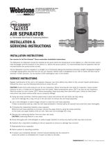
2.1 Engine layout
Also valid for 12V engines
1 Oil cooler
2 Coolant expansion tank
3 Crankcase breather
4 Air filter
5 Exhaust turbocharger
6 Intercooler
7 Cylinder head
8 Charge-air pipework
9 Oil filler neck
10 Oil pan
11 Engine mounting
12 HP fuel pump
13 Automatic oil filter
14 Fuel filter
15 Centrifugal oil filter(s)
16 Coolant cooler
Engine model designation
Key to the engine model designations 16V 4000 Mxyz
12, 16 Number of cylinders
V Cylinder arrangement: V engine
4000 Series
M Application
x Application segment (1, 2 )
y Design index (3)
z R (reduced power/speed)
L (enhanced power/speed)
16 | General Information | MS150045/02E 2013-07
TIM-ID: 0000009991 - 004

2.2 Product description
Description of the engine
Engine
The engine is a liquid-cooled four-stroke diesel engine, rotating counterclockwise (seen from driving
end), with direct injection, sequential turbocharging and charge-air cooling.
The engine is monitored by an engine control and monitoring system (ADEC).
Monitoring in the engine room is carried out by the engine control and monitoring unit (LOP).
Fuel system
Electronically controlled common-rail-injection system with HP pump, pressure accumulator (rail) and
single injectors with integrated individual store.
The electronic control unit controls
• Start of injection
• Injection quantity
• Injection pressure
Exhaust system
The exhaust system is equipped with triple-walled, water-cooled exhaust lines.
The triple-walled design permits
• low surface temperature,
• reduced amount of heat to be dissipated by the coolant,
• absolute gas-tightness.
Turbocharging
Sequential turbocharging with internal, engine-coolant-controlled charge-air cooling. The right-hand ex-
haust turbocharger is cut-in and cut-out on 12V and 16V engines with electronically-controlled, hydraul-
ically-actuated flaps.
Cooling system
Engine cooling as split-circuit cooling system with plate-core heat exchanger.
Heating of the charge air in idle and low-load operation prevents white smoke formation.
Seawater only flows through engine coolant and fuel heat exchanger as well as the raw water pump.
Service block
The service components are mounted on the auxiliary PTO end.
The arrangement facilitates easy access for maintenance operations.
Service components:
• Raw water pump, coolant pump
• Fuel duplex filter, switchable
• Automatic oil filter
• Centrifugal lube oil filter
• Coolant expansion tank
Electronic system
Electronic control and monitoring system with integrated safety and test system, providing interfaces to
Remote Control System (RCS) and Monitoring and Control System (MCS).
MS150045/02E 2013-07 | General Information | 17
TIM-ID: 0000010056 - 005

Engine Interface Module (EIM)
The Engine Interface Module (EIM) is the central connection box on the engine. Covers the entire mini-
mum scope of a marine engine. Has no controls or parts requiring maintenance.
Functions:
• Starter control (start repetition, tooth alignment, starter protection)
• Generator monitoring
• Open bus interface to the plant (SAE J1939)
• Emergency stop function with line break monitoring
• Redundant power supply
• Optional control of emergency air-shutoff flaps
• Key switch logic
• Interface to ECU and EMU
• MCS5 dialog interface
• Control of an MTU lube-oil priming pump (power components in separate MTU PPC Box)
• Connection facility for an MTU Local Operating Station (LOS)
• Serial RS422 interface for diagnosis
The engine interface comprises two parts. The first part is connected to the engine wiring harness via a
62-pole Tyco connector X52. The second part comprises signals at higher current levels. These signals
are led out via M threaded pins and also connected to the engine wiring harness.
Functions
• ECU supply
• EMU supply
• Plant signals (ECU7 connector X1)
• Bus interface (2x MCS5 CAN)
• CAN dialog output (1xMCS5 CAN)
• ECU and EMU emergency stop
• Electric starter
• Terminal 45 of starter A/B (starter engaged)
• Pneumatic starter
• Start-air pressure valve
• Start-air pressure sensor
• Barring gear (barring gear 1 and 2)
• Generator (with excitation control)
• Optional shut-down air flaps
• Control SSK 1+2
• Feedback SSK 1+2
Electronic Engine Control Unit (ECU)
Functions:
• Engine speed control with fuel and speed limitation dependent on engine status and operating condi-
tions;
• Control of sequential turbocharging, cylinder bank cut-out and air recirculation function.
• Data processing logistics for analog and binary signals;
• Interface for data transfer to CAN field bus for remote control and ship-side monitoring;
• RS 232 interface for connection of MTU dialog unit.
Electronic Engine Monitoring Unit (EMU), optional
Functions:
• Data processing logistics for analog and binary signals;
• Interface for data transfer to CAN field bus for remote control and ship-side monitoring.
18 | General Information | MS150045/02E 2013-07
TIM-ID: 0000010056 - 005

Electronic Gear Control Unit (GCU), ship-side wall-mounting
Functions:
• Date processing logistics for gear coupling control;
• Input/output signals as well as data transfer to CAN field bus for remote control and ship-side moni-
toring.
Monitoring in engine room
Engine control and monitoring unit (LOP)
Functions:
• Alphanumeric, monochrome LCD display for monitoring of measured values as well as alarms when
limits are violated;
• Pushbuttons for menu control and dimming unit;
• Combined control and display elements for local engine/gear control;
• Flashing light and horn for combined alarm in engine room;
• Interface to CAN field bus for connected, communicating monitoring system components.
SOLAS – Fire safety requirements
All lines with SOLAS-compliant covers for pipe connections, according to MTU standard MTN5233, are
shown below.
Fuel system, fuel lines with fuel pressures exceeding 1.8 bar
1 Fuel line to fuel filter head
MS150045/02E 2013-07 | General Information | 19
TIM-ID: 0000010056 - 005

1 Fuel line from/to fuel filter head
1 Fuel line to HP pump
Lube oil system, oil lines with oil pressures exceeding 1.8 bar
1 Parting line ETC oil supply free end
20 | General Information | MS150045/02E 2013-07
TIM-ID: 0000010056 - 005
/