Page is loading ...

en-GB 2 775 269
Issue 2.0
Operator's manual
Scania 2.1

OPM 520 en-GB 2
© Scania CV AB 2018, Sweden
Introduction . . . . . . . . . . . . . . . . . . . . . . . . . . . . 3
Responsibility . . . . . . . . . . . . . . . . . . . . . . . . . 3
Display languages . . . . . . . . . . . . . . . . . . . . . . 3
System overview . . . . . . . . . . . . . . . . . . . . . . . . 4
Classified control system . . . . . . . . . . . . . . . . . . 4
Non-classified control system. . . . . . . . . . . . . . . 5
Description of component parts . . . . . . . . . . . . 6
Main display . . . . . . . . . . . . . . . . . . . . . . . . . . 6
Auxiliary display. . . . . . . . . . . . . . . . . . . . . . . 6
Network switch . . . . . . . . . . . . . . . . . . . . . . . . 6
Safety device unit . . . . . . . . . . . . . . . . . . . . . . 7
Gateway . . . . . . . . . . . . . . . . . . . . . . . . . . . . . 7
Control panel. . . . . . . . . . . . . . . . . . . . . . . . . . 7
Fuel leakage monitor. . . . . . . . . . . . . . . . . . . . 8
Monitor for detecting water in fuel . . . . . . . . . 8
Using the displays . . . . . . . . . . . . . . . . . . . . . . . 9
Password . . . . . . . . . . . . . . . . . . . . . . . . . . . . . 9
Buttons on the displays . . . . . . . . . . . . . . . . . . 9
Functions and display modes . . . . . . . . . . . . . 9
Adjusting the brightness of the displays . . . . 12
Status bar. . . . . . . . . . . . . . . . . . . . . . . . . . . . 12
Starting the engine . . . . . . . . . . . . . . . . . . . . 15
Stopping the engine. . . . . . . . . . . . . . . . . . . . 15
Switch off the voltage . . . . . . . . . . . . . . . . . . 15
Alarms. . . . . . . . . . . . . . . . . . . . . . . . . . . . . . 15
Main menu . . . . . . . . . . . . . . . . . . . . . . . . . . . . 16
Ignition Off . . . . . . . . . . . . . . . . . . . . . . . . . . 16
Black Panel Mode . . . . . . . . . . . . . . . . . . . . . 16
Settings . . . . . . . . . . . . . . . . . . . . . . . . . . . . . 17
Backlight . . . . . . . . . . . . . . . . . . . . . . . . . . . . 18
Torque Limit . . . . . . . . . . . . . . . . . . . . . . . . . 19
Fixed Speed. . . . . . . . . . . . . . . . . . . . . . . . . . 19
Adjust Fixed Speed . . . . . . . . . . . . . . . . . . . . 20
Single Speed . . . . . . . . . . . . . . . . . . . . . . . . . 21
Emission level . . . . . . . . . . . . . . . . . . . . . . . . 21
Active Station . . . . . . . . . . . . . . . . . . . . . . . . 22
Log & Counters. . . . . . . . . . . . . . . . . . . . . . . 23
Camera . . . . . . . . . . . . . . . . . . . . . . . . . . . . . 23
Help. . . . . . . . . . . . . . . . . . . . . . . . . . . . . . . . 24
Alarm list . . . . . . . . . . . . . . . . . . . . . . . . . . . . . 25
Typefaces and background colours. . . . . . . . 25
Filtering alarms . . . . . . . . . . . . . . . . . . . . . . . 27
Turning off the buzzer during an alarm . . . . 27
Acknowledging 1 alarm . . . . . . . . . . . . . . . . 27
Acknowledging all alarms . . . . . . . . . . . . . . 27
Safety device unit . . . . . . . . . . . . . . . . . . . . . . . 28
Buttons . . . . . . . . . . . . . . . . . . . . . . . . . . . . . 28
LEDs . . . . . . . . . . . . . . . . . . . . . . . . . . . . . . . 29
Engine shutdown at engine overspeed . . . . . 30
Engine shutdown due to signal from sensor . 31
Relays . . . . . . . . . . . . . . . . . . . . . . . . . . . . . . 31
Shutdown Coil. . . . . . . . . . . . . . . . . . . . . . . . 32

OPM 520 en-GB 3
© Scania CV AB 2018, Sweden
Introduction
Introduction
This Operator's manual describes the operation
of Scania instrumentation.
The information in this manual was correct at the
time of going to press. Scania reserves the right
to make alterations without prior notice.
Note:
Always use Scania spare parts for maintenance
and repair.
REQUIREMENT!
Work on the low voltage circuit should only be
carried out by qualified and experienced person-
nel.
Work on the high voltage circuit may only be
carried out by an authorised electrician.
Responsibility
It is the responsibility of the installer to ensure
that the installation of the electrical system is
carried out in a professional manner. It is also the
responsibility of the installer to ensure that the
system is working satisfactorily and that all com-
ponent parts meet legal requirements and regula-
tions.
Display languages
In this Operator's manual the display interfaces
are shown in English. It is however possible to
set other languages.

System overview
OPM 520 en-GB 4
© Scania CV AB 2018, Sweden
System overview
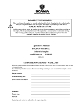
Classified control system
The illustration shows an example of a control system that is prepared for classification.
1
2
2
3
1
4
8
7
6
5
1
9
10
402 114
1. Control panel (option).
2. Auxiliary display (RP, option).
3. Network switch (option).
4. Main display (DCU).
5. Safety device unit (SDU).
6. Junction box.
7. Gateway (option).
8. Monitors on the engine required for classification.
9. Sensor for checking fuel leakage (classified engines with XPI).
10. Sensor for checking water in fuel (engines with XPI).

System overview
OPM 520 en-GB 5
© Scania CV AB 2018, Sweden
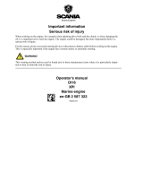
Non-classified control system.
The illustration shows an example of a control system which is not prepared for classification, i.e. a system
without safety device units.
12
13
54
6
402 115
1. Control panel (option).
2. Auxiliary display (option).
3. Main display.
4. Junction box.
5. Gateway (option).
6. Sensor for checking water in fuel (engines with XPI).

OPM 520 en-GB 6
© Scania CV AB 2018, Sweden
System overview
Description of component
parts
Main display
The main display is the main component in the
control system. Values from the engine sensors
are shown on the display. Commands and other
user functions are also carried out on the main
display.
Contact an authorised Scania workshop if the
main display needs to be configured.
Auxiliary display
The auxiliary display, which is optional, shows
the same things as the main display, with the
same user interface.
The auxiliary display does not need configuring,
as it loads the configuration from the main dis-
play which it is connected to. If the configuration
of the main display has been changed, the auxil-
iary display adapts automatically to the new con-
figuration. Therefore, it is easy to supplement the
control system with an auxiliary display after-
wards.
Network switch
A network switch is only required if more than
1 auxiliary display is connected to the control
system. The displays can then be connected to-
gether via a network cable.
Scania recommends using a network switch, in
order to make it simpler to expand the control
system and connect a computer.

System overview
OPM 520 en-GB 7
© Scania CV AB 2018, Sweden
Safety device unit
The safety device unit is a requirement for clas-
sified control systems. The safety device unit has
the same monitoring and shut-off functions as
the main display.
Gateway
The gateway, which is an option, reads messages
about position and speed via NMEA 2000, so
that the control system can calculate fuel con-
sumption per nautical mile.
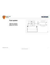
Control panel
With the control panel, which is an option, the
engine can be started and shut down. Using it, it
is also possible to activate two engine speed set-
tings.
Starter lock
The control panel starter lock (4) is used to start
and stop the engine. The starter lock has the fol-
lowing positions:
• Position 0: The engine electrical system is
switched off and the engine is stopped.
• Position 1: The engine electrical system is ac-
tivated.
• Position 2: The starter motor is activated.
331 245
4
5
6
1
2
3
Control panel.
1. Control for activating engine speed setting 1.
2. Control for activating engine speed setting 2.
3. Control for activating engine speed setting 1 or
2.
4. Starter lock.
5. Not used.
6. Not used.

System overview
OPM 520 en-GB 8
© Scania CV AB 2018, Sweden
Fuel leakage monitor
On classified XPI engines, there is a monitor
which detects fuel leakage from the high pres-
sure pipes. If there is leakage, a warning comes
on in the main display.
Monitor for detecting water in
fuel
Engines with XPI use water-separating fuel fil-
ters. A monitor converts the water level in the fil-
ter to an electric signal which is sent to the main
display.

Using the displays
OPM 520 en-GB 9
© Scania CV AB 2018, Sweden
Using the displays
The way the displays function depends on how
the main display is configured. Configuration of
the main display is not described in this Opera-
tor's manual. Contact an authorised Scania work-
shop if this needs to be carried out.
Password
If the control system does not have a control pan-
el, a 4-digit password is used instead of a starter
key. The password is provided by the installer.
Buttons on the displays
On the right-hand side of the displays, there are
four buttons for direct access to the following
features:
1. First instruments page and Menu
2. Alarm list
3. Starting the engine
4. Engine shutdown
Functions and display modes
The displays are touch screens where you carry
out every command by pressing directly on the
display. Different touch areas on the display
have different functions. For example, if you
touch the left-hand side of the display on an in-
strument page, you get to the previous instru-
ment page.
The displays have four different display modes:
• Instrument pages
•Alarm list
• Select Page
• Menu
1
2
3
4
381 113
Display buttons.
1. Home button.
2. Alarm list.
3. Starting the engine.
4. Engine shutdown.

Using the displays
OPM 520 en-GB 10
© Scania CV AB 2018, Sweden
Instrument pages
There are 4 preset instrument pages. If additional
instrument pages have been configured, there
may be more instrument pages.
363 210
651
1000
1500
500
0
2500
2000
Running
Boost Pressure
2,00
4,00
5,001,00
0,00
1,06
3,00
Batte
r
y
V
oltage
28,0
V
Fuel Rate
2,6
l/h
Throttle
P
osition
0
%
% Load
11
%
Engine Oil
T
empe
r
ature
80
°
C
Engine Speed
Running
Engine Speed
Engine Oil
Pres
s
.
bar
bar
Boost
Pressure
80
100
120
60
40
Coolant
T
em
p
.
100
50
0
0
50
100
651
13
2.6
2.5
1.06
1000
1500
500
0
2500
10.0
5.00
4.00
3.00
2.00
1.00
0.00
8.0
6.0
4.0
0.0
2000
Running
Engine Speed
651
Batte
r
y
V
oltage
28,0
V
13
h
Running
Engine Speed
1000
1500
500
0 0
2500
651
°
C
°
C
2.5
RPM
RPM
RPM
bar
Engine Oil Pres
s
.
13
0 %
11 %
h
Batte
r
y
V
oltage
Engine Hours
Engine Hours
Engine Hours
Fuel Rate
% Load
Throttle
Position
h
l/h
28,0
V
2000
80
100
120
60
40
0.0
2.0
4.0
6.0
8.0
10.0
2.5
bar
Engine Oil Pres
s
.
0.0
2.0
4.0
6.0
8.0
10.0
Coolant
T
em
p
.
80
°
C
80
100
120
60
40
Coolant
T
em
p
.
80
1000
1500
500
2500
2000
BL -
BL +
BL -
BL +
BL -
BL +
BL -
BL +
The 4 preset instrument pages.

Using the displays
OPM 520 en-GB 11
© Scania CV AB 2018, Sweden
To navigate between the instrument pages:
• You scroll between the instrument pages by
pressing on the right- or left-hand side of the
display. See illustration.
• You reach the first instrument page, by press-
ing the home key briefly. See illustration.
Note: A longer press on the home button (1
second) will open the main menu instead.
Select Page
You get to Select Page by pressing in the middle
of the display when on one of the instrument
pages.
In Select Page thumbnails of the instrument pag-
es and the Menu are shown. Select the instrument
page you wish to display by pressing the corre-
sponding thumbnail, or select Menu.
Running
Engine Speed
1000
1500
500
0
2500
651
°
C
2.5
RPM
bar
13
h
Engine Hours
28,0
V
2000
80
100
120
60
40
0.0
2.0
4.0
6.0
8.0
10.0
80
BL -
BL +
Coolant Temp.
Engine Oil Press.
Battery Voltage
383 548
381 126
Ready
Engine Speed
651
Batte
r
y
V
oltage
28,0
V
13
h
0
Engine Hour s
1000
1500
500
2500
2000
BL - BL +
Engine Speed
Engine Oil
Pres
s
.
bar bar
Boost
Pressure
80
100
120
60
40
Coolant
T
em
p
.
100
50
0
0
50
100
651
13
2.6
2.5
1.06
1000
1500
500
0
2500
10.0
5.00
4.00
3.00
2.00
1.00
0.00
8.0
6.0
4.0
0.0
2000
°
C
RPM
0 %
11 %
Engi ne Hours
Fuel Rate
% Load
Throttle
P
osition
h
l/h
BL - BL +
Engine Speed
1000
1500
500
0
2500
651
°
C
2.5
RPM
bar
Engine Oil Pres
s
.
13
h
Batte
r
y
V
oltage
Engine Hours
28,0
V
2000
80
100
120
60
40
0.0
2.0
4.0
6.0
8.0
10.0
Coolant
T
em
p
.
80
BL - B L +
381 128
Select
P
age
P
age 1
P
age 4
P
age 2
P
age 3
Menu
651
1000
1500
500
0
2500
2000
Boost Pressure
2,00
4,00
5,001,00
0,00
1,06
3,00
Batte
r
y
V
oltage
28,0
V
Fuel Rate
2,6 l/h
Throt tle
P
osition
0
%
% Load
11
%
Engine Oil
T
empe
r
ature
80
°
C
Engine Speed
RPM
2.5
bar
Engine Oil Pres
s
.
0.0
2.0
4.0
6.0
8.0
10.0
°
C
80
100
120
60
40
Coolant
T
em
p
.
80
BL - BL +
Settings
Ready
Menu
Ignition off
01
Black Panel Mode
(Disabled)
Fixed Speed
[Off]
T
orque Limi t
[Curve 0]

Using the displays
OPM 520 en-GB 12
© Scania CV AB 2018, Sweden
Adjusting the brightness of
the displays
You can increase and decrease the brightness by
pressing BL- and BL+ on one of the instrument
pages.
Status bar
On the upper part of the displays there is a status
bar. Engine status is displayed on the left-hand
side of the status bar and the display status on the
right-hand side.
Engine status
When the engine is started the status in the top
left of the status bar changes from Ready to Run-
ning.
When the engine is switched of, the status chang-
es from Running to Ready.
Running
Engine Speed
1000
1500
500
0
2500
651
°
C
2.5
RPM
bar
13
h
Engine Hours
28,0
V
2000
80
100
120
60
40
0.0
2.0
4.0
6.0
8.0
10.0
80
BL -
BL +
Coolant Temp.
Engine Oil Press.
Battery Voltage
383 547
Decrease and increase the brightness of the dis-
plays.
°
C
13
h
28,0
V
6.0
BL -
BL +
1000
1500
500
0
2500
651
2.5
RPM
bar
2000
80
100
120
60
40
0.0
2.0
4.0
8.0
10.0
80
Engine Speed
Engine Hours
Running
Coolant Temp.
Engine Oil Press.
Battery Voltage
383 543
Status bar on an instrument page.

Using the displays
OPM 520 en-GB 13
© Scania CV AB 2018, Sweden
Display status symbols
The following display status symbols may be
shown on the top right-hand side of the status
bar:
Symbol Meaning Explanation
Remote mode The engine can be started and stopped from both the main
display and an auxiliary display.
Local mode The engine can only be started and stopped from the main
display.
Override of engine shut-
down
If this function is activated, an alarm is only given for
events which normally lead to engine shutdown. The ex-
ception is engine overspeed, which is always activated.
Everything OK There are no alarms in the alarm list.
IMO Tier II The system is running at emission standard IMO Tier II.
IMO Tier III The system is running at emission standard IMO Tier III.
Fault in exhaust gas after-
treatment management sys-
tem
The engine is not running at the selected emission stand-
ard.
If the status bar lights up yellow and the icon is displayed,
the problem is not critical but should be rectified as soon
as possible.
If the status bar lights up red and the icon is displayed, the
fault critical and must be rectified immediately.
Low level of urea in the re-
ductant tank
If the icon has a steady light, the level in the reductant
tank is low.
If the icon flashes every other second (1/2 Hz), the level
in the reductant tank is very low.
If the icon flashes twice per second (2 Hz), the reductant
tank is empty.
Gear engaged (unspecified) Forward or reverse gear is engaged. The symbol is only
displayed if the gear position function has been config-
ured in the main display.
Forward gear engaged The symbol is only displayed if the gear position function
has been configured in the main display.
347 940
347 941
347 942
STOP
347 943
402 022
402 023
402 021
402 116
383 554
383 553

Using the displays
OPM 520 en-GB 14
© Scania CV AB 2018, Sweden
Note:
Several symbols can be shown simultaneously.
Reverse engaged The symbol is only displayed if the gear position function
has been configured in the main display.
Neutral gear The symbol is only displayed if the gear position function
has been configured in the main display.
Active display This symbol is only displayed in auxiliary displays, if
present. It indicates that the auxiliary display is in charge
and is controlling the engine.
Maintenance due If a maintenance interval has been configured, this sym-
bol shows that maintenance is due.
Symbol Meaning Explanation
383 552
383 551
383 550
383 549

Using the displays
OPM 520 en-GB 15
© Scania CV AB 2018, Sweden
Starting the engine
Hold the start button (1) in until the engine starts.
When the engine has started the status in the top
left of the status bar changes from Ready to Run-
ning.
Stopping the engine
Press and hold the engine shutdown button (2)
until the engine shuts down. When the engine
has stopped the status in the top left of the status
bar changes from Running to Ready.
Switch off the voltage
Turn the key in the control panel. If the system
does not have a control panel, press the Ignition
Off button under Menu.
Note:
If there are multiple displays in the system and
another display is in control, it can keep the sys-
tem going.
Alarms
All alarms end up in the alarm list. Only impor-
tant faults are displayed in the status bar.
Each time a new alarm is added to the alarm list,
the following happens:
• The buzzer sounds.
• The status bar flashes either yellow or red.
The colour in the status bar has different mean-
ings:
• Yellow means warning.
• Red means alarm or engine shutdown.
Note:
A red alarm always takes precedence over a yel-
low warning if both are generated simultaneous-
ly.
For further information on alarms, see the sec-
tion Alarm list
.
1
2
381 127
01
383 555

Main menu
OPM 520 en-GB 16
© Scania CV AB 2018, Sweden
Main menu
There are 2 different ways to get to the main
menu (Menu):
• Press the home button for one second (see im-
age).
Note: A brief press of the home button will
take you to the first instrument page instead.
• Press in the middle of the display on one of
the instrument pages and then select Menu.
When the Menu is opened the most recently used
function is preselected. The functions in Menu
are described in the following pages.
Ignition Off
Cuts the voltage.
Note:
The button is only displayed if the system does
not have a control panel.
Black Panel Mode
The function is used to switch off the display to
improve visibility in the dark.
Press the button to switch off the display com-
pletely. If you touch the display when the func-
tion is activated, the display comes on at the
lowest brightness. It switches off automatically
after a preset time. The standard setting is
5 seconds.
In the case of a serious faults, the display comes
on even if Black Panel Mode is activated. How-
ever, with a less serious fault, only the buzzer
sounds.
The function is deactivated by pressing the but-
ton again.
381 126
01
383 555
383 556

Main menu
OPM 520 en-GB 17
© Scania CV AB 2018, Sweden
Settings
In Menu > Settings all display settings are made.
In the main display, Settings consists of multiple
pages. In any auxiliary displays, Settings consists
of one page.
Setting Symbol Explanation
Mode Select the main display operating mode. There are 2 modes to choose
from:
Remote mode: The engine can be started and stopped from both the
main display and an auxiliary display.
Local mode: The engine can only be started and stopped from the
main display.
Note: The button is only on the main display, not on any auxiliary
displays.
Start Disabled
Select Active to deactivate engine start. Note: The button is only on
the main display, not on any auxiliary displays.
Shutdown Override
Select Active to activate engine shutdown override control. Then,
events which normally lead to engine shutdown are signalled with an
alarm only. However, engine overspeed is always enabled. Note: The
button is only on the main display, not on any auxiliary displays.
Prelube Override
The button is only on the main display, not on any auxiliary displays,
and the function is not used.
Button Beep
Select Enabled if you want a sound to be made every time you press
the display. Select Disabled if no sound should be made when you
press the display.
Language
Select language. The languages which can be selected depend on how
the display is configured.
Units Select unit of measurement: Metric or U.S.
Wallpaper
Here you choose between different backgrounds for the instrument
pages, for the Menu and for dialogue boxes.
383 557
347 940
347 941
381 140
STOP
381 141
381 142
381 143
381 144
381 146
381 147

Main menu
OPM 520 en-GB 18
© Scania CV AB 2018, Sweden
Backlight
Note:
The button is only on any additional display, not
on the main displays.
Here you can adjust the brightness of the auxilia-
ry display. You can also adjust the brightness
with BL+ and BL- on the instrument pages.
Engine Overspeed
Test
Select Active to activate the engine overspeed test. When the engine
overspeed test is activated, the limit value for engine overspeed is
temporarily reduced to the nominal engine speed (engine speed is in-
dicated on the engine data plate). Start the engine to carry out the test.
The engine overspeed test is deactivated automatically after a timeout
or when actual engine overspeed is detected in the test.
Note: The button is only on the main display, not on any auxiliary
displays.
Connect a PC
This function is used when configuring the main display and updat-
ing software. Contact an authorised Scania workshop if any of this
needs to be carried out.
Note: The button is only on the main display, not on any auxiliary
displays.
Administration
In the administration section the display is configured, which can
only be done by an authorised Scania workshop. It is therefore pass-
word-protected.
Setting Symbol Explanation
381 148
381 149
381 150
383 561

Main menu
OPM 520 en-GB 19
© Scania CV AB 2018, Sweden
Torque Limit
When you press Torque Limit , the Torque Limit
Selection window opens.
Torque limitation is different types of power
curves which the engine should follow. Power
curves can only be configured by an approved
Scania workshop.
Note:
Customer defined engine torques are always
lower than the maximum engine torque.
Fixed Speed
When you press Fixed Speed, the Mode window
opens.
Here you activate and deactivate the engine
speed setting. You can choose from the follow-
ing options:
In order to activate engine speed setting 1 or 2,
the engine must be running, the display in ques-
tion must have control (active display) and the
throttle must be at 0%.
Setting Description
Curve 0 Maximum engine torque.
Curve 1 Maximum engine torque, an-
other lower engine torque re-
quested.
Curve 2 Customer defined engine
torque.
Curve 3 Customer defined engine
torque.
Input Controlled Activation of curve 1-3 via in-
puts on the main display, if this
has been configured.
Setting Description
Fixed Speed
Mode 1
Activate engine speed setting 1.
Fixed Speed
Mode 2
Activate engine speed setting 2.
Fixed Speed Off Deactivate engine speed setting.
383 558
Cu
r
v
e 0
363 213
Running
T
orque Limit Selection
Cu
r
v
e 1
Cu
r
v
e 2
Cu
r
v
e 3
0 1
2 3
Input Controlled
[Cu
r
v
e 0]
402 026
Fixed Speed Mode 1
347 952
Running
Mode
Fixed Speed Mode 2
Fixed Speed Off
1 2

Main menu
OPM 520 en-GB 20
© Scania CV AB 2018, Sweden
Adjust Fixed Speed
When you press Adjust Fixed Speed, the Fixed
Speed Adjustment window opens. Here you ad-
just engine speed setting 1 and 2.
You can only adjust an engine speed setting if
you have first activated it. This can be done in 2
different ways:
•Via Menu > Fixed Speed in the displays, see
the previous section.
• Via the engine speed setting control on the
control panel.
The following 2 engine speed settings are in Ad-
just Fixed Speed:
• Fixed Speed Mode 1 is an engine speed which
can be set between high and low idling. High
and low idling vary depending on the type of
engine.
• Fixed Speed Mode 2 is an engine speed which
can be set between 450 and 2,000 rpm.
Proceed as follows to adjust engine speed setting
1 or 2:
1. Select the engine speed setting to be adjust-
ed.
2. Press the activate button, i.e. the arrow but-
ton underneath the minus button for 3 to 6 s
to access the adjustment mode.
3. Step to the desired engine speed using the +
and - buttons.
4. Save the desired engine speed by keeping the
activate button depressed for 3 to 6 seconds.
No confirmation is shown but the setting is
saved.
5. Exit the menu by pressing the return arrow.
When either of the engine speed settings is acti-
vated, the engine speed goes up or down to the
last saved engine speed setting.
A Scania workshop can set the torque limit for
both engine speed settings. The engine speed set-
tings are isochronous.
383 562
347 953
Running
Fixed Speed Adjustment - Mode 1
Engine Speed
1000 1500
500 2000
1
/