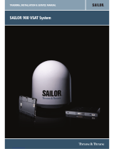
COBHAM SAILOR 100 GX Installation guide
- Category
- Television antennas
- Type
- Installation guide

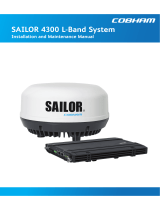
SAILOR 100 GX
Installation manual

SAILOR 100 GX
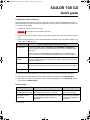
Quick guide
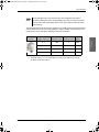
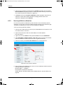
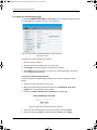
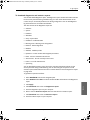
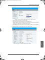
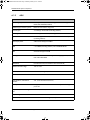
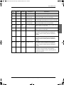
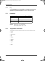
Configuration tasks (minimum)
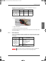
This quick guide aims at experienced service personnel who have installed the SAILOR 100 GX system
and connected power. It lists the minimum configuration tasks you have to make before the system can
be used on-air on a satellite.
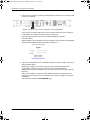
1. Switch on the Antenna Control Unit only.
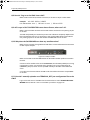
2. Connect a PC to the front LAN connector or the LAN3 connector at the rear of the Antenna Control
Unit.
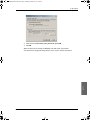
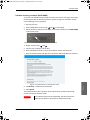
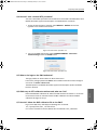
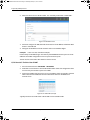
3. Open an Internet Browser to access the SAILOR 100 GX: IP address: http://192.168.0.1 (default), user
name: admin, password: 1234.
4. Switch on the modem and wait for the modem to boot and perform the initial BUC calibration.
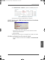
5. Verify that the SAILOR 100 GX acquires the GX satellite (ACU display shows ACQUISITION).
6. Verify that the system is operational. The status in the ACU display must show TRACKING and the
upper status line MDM: NETOK.
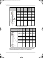
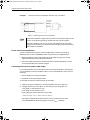
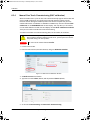
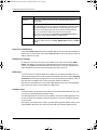
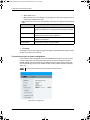
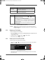
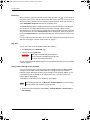
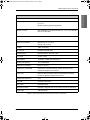
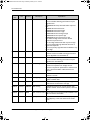
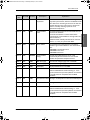
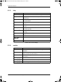
Possible issues
98-141779-C
Important
Do not switch on the modem at this point.
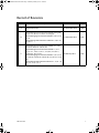
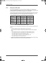
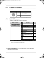
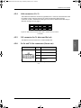
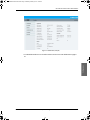
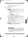
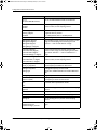
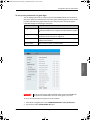
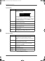
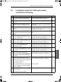
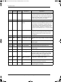
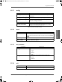
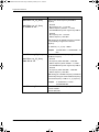
Configuration task What to do and where to find more information
Heading input
Configure the heading input to External under SETTINGS > Navigation. For
more information see Select the desired heading input, see the following table.
on page 6-4.
Connect the ship’s heading (NMEA0183, RS-422/RS-232) to the NMEA 0183
multi-connector. For more information see NMEA 0183 connector on page 4-4.
Azimuth
calibration
Make an azimuth calibration under SERVICE > Calibration to ensure that the
antenna can point and receive a signal from the satellite. For more information see
Calibration on page 6-7.
Cable calibration
Make a cable calibration under SERVICE > Calibration to ensure that the cable
loss is calculated properly. For more information see Cable calibration on page 6-
11.
Satellite profile
Activate the satellite profile with the GX Modem.
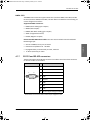
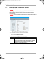
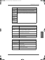
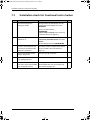
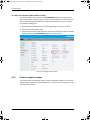
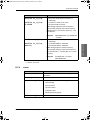
Symptom Cause Remedy
The display shows BUC
CALIBRATION OUTDATED.
The GMU has been connected to the antenna
before the cable calibration was done.
Use the GMU dashboard to
perform OTC manually.
Status does not show
MDM: NETOK.
Check if the GMU has RX locked status Locked,
TX allowed YES and BUC TX ON (ACU
Dashboard).
If yes, consult your provider
to confirm that the GMU is
provisioned.
SAILOR100GX-IM-98-141779.book Page i Wednesday, February 22, 2017 12:30 PM

SAILOR 100 GX
Installation manual
Document number: 98-141779-C
Release date: 22 February 2017
SAILOR100GX-IM-98-141779.book Page i Wednesday, February 22, 2017 12:30 PM

ii 98-141779-C
Disclaimer
Any responsibility or liability for loss or damage in connection with the use of this product and the
accompanying documentation is disclaimed by Thrane & Thrane A/S. The information in this manual is
provided for information purposes only, is subject to change without notice and may contain errors or
inaccuracies. Manuals issued by Thrane & Thrane A/S are periodically revised and updated. Anyone
relying on this information should acquire the most current version e.g. from www.cobham.com/satcom,
Cobham SYNC Partner Portal, or from the distributor. Thrane & Thrane A/S is not responsible for the
content or accuracy of any translations or reproductions, in whole or in part, of this manual from any
other source. In the event of any discrepancies, the English version shall be the governing text.
Thrane & Thrane A/S is trading as Cobham SATCOM.
Copyright
© 2017 Thrane & Thrane A/S. All rights reserved.
Trademark acknowledgements
• Inmarsat is a registered trademark of the International Maritime Satellite Organisation (IMSO) and is
licensed by IMSO to Inmarsat Limited and Inmarsat Ventures plc.
• Some product and company names mentioned in this manual may be trademarks or trade names of
their respective owners.
GPL notification
The software included in this product contains copyrighted software that is licensed under the GPL/LGPL.
The verbatim licenses can be found online at:
http://www.gnu.org/licenses/old-licenses/gpl-2.0.html
http://www.gnu.org/licenses/old-licenses/lgpl-2.1.html
You may obtain the complete corresponding source code from us for a period of three years after our last
shipment of this product, which will be no earlier than 2021, by sending a money order or check for DKK
50 to:
SW Technology/GPL Compliance,
Cobham SATCOM (Thrane & Thrane A/S),
Lundtoftegaardsvej 93D
2800 Lyngby
DENMARK
Write "source for product SAILOR 100 GX" in the memo line of your payment. This offer is valid to anyone
in receipt of this information.
http://www.cobham.com/about-cobham/communications-and-connectivity/about-us/satcom/free-and-
open-source-software-(foss).aspx
SAILOR100GX-IM-98-141779.book Page ii Wednesday, February 22, 2017 12:30 PM

98-141779-C iii
Safety summary
The following general safety precautions must be observed during all phases of operation,
service and repair of this equipment. Failure to comply with these precautions or with specific
warnings elsewhere in this manual violates safety standards of design, manufacture and
intended use of the equipment. Thrane & Thrane A/S assumes no liability for the customer's
failure to comply with these requirements.
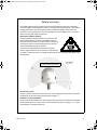
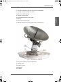
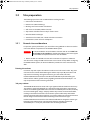
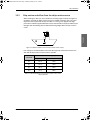
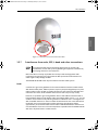
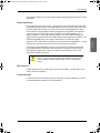
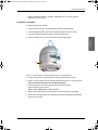
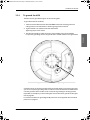
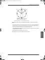
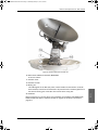
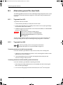
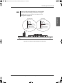
Microwave radiation hazards
During transmission the Above Deck Unit (antenna) in this
system radiates Microwave Power.This radiation may be
hazardous to humans close to the Above Deck Unit. During
transmission, make sure that nobody gets closer than the
recommended minimum safety distance.
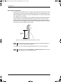
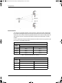
The minimum safety distance to the Above Deck Unit
reflector on the focal line is 30 m, based on a radiation level
of 10 W/m
2
. No hazard exists >25° below the Above Deck Unit’s mounting plane. Refer to the
drawing below.
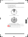
No-transmit zones
In order to protect personnel no-transmit zones can be programmed. For further information
see Blocking zones with azimuth and elevation on page 3-5.
Distance to other equipment
Do not move the Above Deck Unit closer to radars than the minimum safe distance specified in
section Interference from radar, GPS, L-band and other transmitters on page 3-13 – it may
cause damage to the Above Deck Unit.
MICROWAVE RADIATION
No personnel within safety distance
Safety distance:
30 m, 10 W/m
2
SAILOR100GX-IM-98-141779.book Page iii Wednesday, February 22, 2017 12:30 PM

iv 98-141779-C
Compass Safe Distance:
SAILOR 100 GX antenna or ADU (Above Deck Unit): min. 100 cm (ENC 60945).
SAILOR 7016C Antenna Control Unit: min. 30 cm (IEC 60945).
SAILOR 7016B Antenna Control Unit: min. 10 cm (IEC 60945).
Service
User access to the interior of the ACU is not allowed. Only a technician authorized by Cobham
SATCOM may perform service - failure to comply with this rule will void the warranty. Access to
the interior of the Above Deck Unit is allowed. Replacement of certain modules and general
service may only be performed by a technician authorized by Cobham SATCOM.
Grounding, cables and connections
To minimize shock hazard and to protect against lightning, you must connect the equipment
chassis and cabinet to an electrical ground. Ground the ACU to the ship. For further details see
Appendix B, Ground and RF protection.
Do not extend the cables beyond the lengths specified for the equipment. The cable between
the ACU and Above Deck Unit can be extended if it complies with the specified data
concerning cable losses etc.
Rx and Tx cables for the SAILOR 100 GX system are shielded and should not be affected by
magnetic fields. However, try to avoid running cables parallel to high power and AC/RF wiring as
this might cause malfunction of the equipment.
Power supply
SAILOR 7016C Antenna Control Unit: voltage range 100-240 VAC.
SAILOR 7016B Antenna Control Unit: voltage range 20-32 VDC.
The Above Deck Unit is powered by the ACU.
The voltage range for the SAILOR 100 GX modem is 100 – 240 VAC. The socket-outlet shall be
installed near the equipment and shall be easily accessible.
Do not operate in an explosive atmosphere
Do not operate the equipment in the presence of flammable gases or fumes. Operation of any
electrical equipment in such an environment constitutes a definite safety hazard.
Keep away from live circuits
Operating personnel must not remove equipment covers. Component replacement and internal
adjustment must be made by qualified maintenance personnel. Do not replace components
with the power cable connected. Under certain conditions, dangerous voltages may exist even
with the power cable removed. To avoid injuries, always disconnect power and discharge
circuits before touching them.
Failure to comply with the rules above will void the warranty!
After installation make this manual available to the user for further reference.
SAILOR100GX-IM-98-141779.book Page iv Wednesday, February 22, 2017 12:30 PM

98-141779-C v
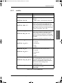
Record of Revisions
Rev. Description Release Date Initials
A Original document 22 September 2014 UFO
B
The following sections have been edited: Quick guide,
3.3.4, 5.3.2, 6.1.2, 6.2.1, 6.2.3, 6.2.5, App. D
The following figures have been edited: 6-3, 6-5, 6-14,
6-18
The following tables have been edited: 6-1, 6-8, 6-14,
6-19, 7-3
15 December 2014 UFO
C
The following sections have been added: 3.5.3, 3.6.1,
4.1.2, 6.2, 8.1.2, 8.1.3, 8.1.4, 8.8
The following sections have been edited: 1.3, 2.1.1,
2.1.3, 3.1.1, 3.4.2, 3.5, 4.1.1, 4.1.3, 6.3, 6.3.1, 6.3.3,
6.4.5, 6.5.1, 8.1.1, 8.2.2
The following figures have been edited: 6-1, 6-3, 6-12,
6-13, 6-22, 6-24, 6-25, 6-26, 6-30, 6-31, 8-13, 8-15, 8-
16
The following tables have been edited: 2-1, 4-7, 6-7, 6-
19, 7-2, A-1, C-1, C-2
22 February 2017 UFO
SAILOR100GX-IM-98-141779.book Page v Wednesday, February 22, 2017 12:30 PM

vi 98-141779-C
SAILOR100GX-IM-98-141779.book Page vi Wednesday, February 22, 2017 12:30 PM

98-141779-C vii
Table of contents
Chapter 1 About this manual
1.1 Intended readers ..............................................................................................................1-1
1.2 Manual overview ...............................................................................................................1-1
1.3 Software version ...............................................................................................................1-1
1.4 Typography ...........................................................................................................................1-2
1.5 Precautions ............................................................................................................................1-2
Chapter 2 Introduction
2.1 SAILOR 100 GX system ................................................................................................2-1
2.1.1 Overview ..................................................................................................................................2-1
2.1.2 Above Deck Unit (ADU) ...................................................................................................2-3
2.1.3 Antenna Control Unit (ACU) ..........................................................................................2-6
2.1.4 GX Modem Unit (modem) ..............................................................................................2-8
2.1.5 Satellite type approvals ....................................................................................................2-8
2.1.6 Service activation ................................................................................................................2-8
2.2 Part numbers and options .........................................................................................2-9
2.2.1 Applicable model and part numbers ..........................................................................2-9
2.2.2 Options for SAILOR 100 GX ...........................................................................................2-9
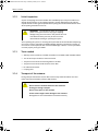
Chapter 3 Installation
3.1 What’s in the box .............................................................................................................3-1
3.1.1 To unpack ...............................................................................................................................3-1
3.1.2 Initial inspection ..................................................................................................................3-2
3.1.3 Tools needed .........................................................................................................................3-2
3.1.4 Transport of the antenna ................................................................................................3-2
3.2 Site preparation .................................................................................................................3-3
3.2.1 General site considerations ............................................................................................3-3
3.2.2 Obstructions (ADU shadowing) ....................................................................................3-4
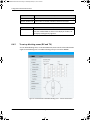
3.2.3 Blocking zones with azimuth and elevation ...........................................................3-5
3.2.4 Safe access to the ADU (radiation hazard) .............................................................3-6
3.2.5 Ship motion and offset from the ship’s motion centre ....................................3-7
3.2.6 Mast foundation and height ..........................................................................................3-8
3.2.7 Interference from radar, GPS, L-band and other transmitters ....................3-13
3.2.8 Condensation, water intrusion and deposits ......................................................3-17
SAILOR100GX-IM-98-141779.book Page vii Wednesday, February 22, 2017 12:30 PM

Table of contents
viii 98-141779-C
3.3 Installation of the ADU ............................................................................................3-18
3.3.1 Overview ...............................................................................................................................3-18
3.3.2 To install the ADU ............................................................................................................3-18
3.3.3 To open and remove the service hatch ................................................................3-22
3.3.4 To ground the ADU .........................................................................................................3-23
3.3.5 Alternative ADU cable ...................................................................................................3-24
3.4 Installation of the ACU ............................................................................................3-25
3.4.1 To install the ACU ............................................................................................................ 3-25
3.4.2 To ground the ACU .........................................................................................................3-25
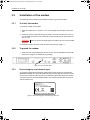
3.5 Installation of the modem .....................................................................................3-26
3.5.1 To install the modem .....................................................................................................3-26
3.5.2 To ground the modem ..................................................................................................3-26
3.5.3 Provisioning key and terminal type .........................................................................3-26
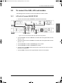
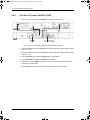
3.6 To connect the ADU, ACU and modem .......................................................3-27
3.6.1 ACU with AC power (SAILOR 7016C) ....................................................................3-27
3.6.2 ACU with DC power (SAILOR 7016B) .................................................................... 3-28
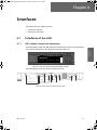
Chapter 4 Interfaces
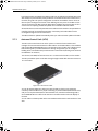
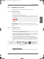
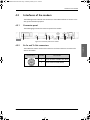
4.1 Interfaces of the ACU ..................................................................................................4-1
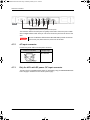
4.1.1 LEDs, display, keypad and connectors ......................................................................4-1
4.1.2 AC input connector ............................................................................................................4-2
4.1.3 Only for ACU with DC power: DC input connector ............................................4-2
4.1.4 ADU connector ....................................................................................................................4-3
4.1.5 Rx In and Tx Out connectors .......................................................................................4-4
4.1.6 NMEA 0183 connector ....................................................................................................4-4
4.1.7 RS-232 and RS-422 connectors ...................................................................................4-5
4.1.8 LAN1 – 4 connectors .........................................................................................................4-6
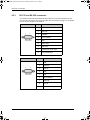
4.2 Interfaces of the modem ...........................................................................................4-7
4.2.1 Connector panel ..................................................................................................................4-7
4.2.2 Rx In and Tx Out connectors .......................................................................................4-7
4.2.3 RS-232 and RS-422 connectors ...................................................................................4-8
4.2.4 LAN connectors (8 + 2) ....................................................................................................4-9
4.2.5 I/O connector for Tx Mute and Rx Lock ..................................................................4-9
4.2.6 Rx In and Tx Out connectors (future use) ..............................................................4-9
SAILOR100GX-IM-98-141779.book Page viii Wednesday, February 22, 2017 12:30 PM

Table of contents
98-141779-C ix
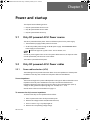
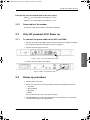
Chapter 5 Power and startup
5.1 Only DC powered ACU: Power source ..............................................................5-1
5.2 Only DC powered ACU: Power cables ...............................................................5-1
5.2.1 Power cable selection (ACU) .........................................................................................5-1
5.2.2 Power cable of the modem ............................................................................................5-3
5.3 Only DC powered ACU: Power up ........................................................................5-3
5.3.1 To connect the power cable to the ACU and GMU ...........................................5-3
5.4 Power-up procedure .......................................................................................................5-3
5.4.1 Initialisation steps in daily use ......................................................................................5-4
5.4.2 SAILOR 100 GX operational ...........................................................................................5-4
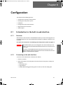
Chapter 6 Configuration
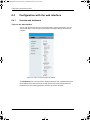
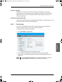
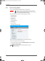
6.1 Introduction to the built-in web interface ..................................................6-1
6.1.1 Overview ..................................................................................................................................6-1
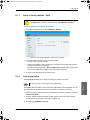
6.1.2 Connecting to the web interface ................................................................................6-1
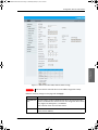
6.2 Heading input and position system ...................................................................6-4
6.3 Calibration .............................................................................................................................6-7
6.3.1 Azimuth calibration ............................................................................................................6-7
6.3.2 Service profile for calibration .....................................................................................6-10
6.3.3 Cable calibration ...............................................................................................................6-11
6.3.4 Manual One Touch Commissioning (BUC calibration) ..................................6-12
6.3.5 Operation in gyro-free mode .............................................................................6-13
6.3.6 Fixed TX IF principle .......................................................................................................6-13
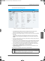
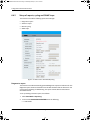
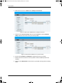
6.4 Configuration with the web interface ...........................................................6-14
6.4.1 Overview and dashboard ..............................................................................................6-14
6.4.2 To set up blocking zones (RX and TX) ....................................................................6-18
6.4.3 To configure the LAN network ..................................................................................6-20
6.4.4 E-mail setup ........................................................................................................................6-23
6.4.5 Setup of reports, syslog and SNMP traps .............................................................6-24
6.4.6 Administration ...................................................................................................................6-29
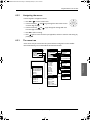
6.5 Keypad and menus of the ACU ..........................................................................6-33
6.5.1 ACU display and keypad ...............................................................................................6-33
6.5.2 Navigating the menus ....................................................................................................6-35
6.5.3 The menu tree ...................................................................................................................6-35
6.5.4 Brightness of the display ..............................................................................................6-38
6.5.5 Power-cycle of the ACU and ADU ...........................................................................6-38
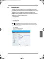
6.6 SNMP support ..................................................................................................................6-39
Chapter 7 Installation check
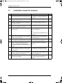
7.1 Installation check list: Antenna ............................................................................7-2
SAILOR100GX-IM-98-141779.book Page ix Wednesday, February 22, 2017 12:30 PM

Table of contents
x 98-141779-C
7.2 Installation check list: ACU and modem, connectors and wiring 7-3
7.3 Installation check list: Functional test in harbor ....................................7-4
Chapter 8 Service
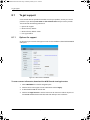
8.1 To get support ....................................................................................................................8-2
8.1.1 Options for support ............................................................................................................8-2
8.1.2 Reset to factory default ...................................................................................................8-6
8.1.3 Reset to factory default - GMU ....................................................................................8-7
8.1.4 Line up procedure ...............................................................................................................8-7
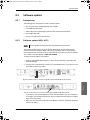
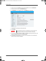
8.2 Software update ................................................................................................................8-9
8.2.1 Prerequisites ..........................................................................................................................8-9
8.2.2 Software update (ADU, ACU) ........................................................................................8-9
8.2.3 Software update (modem) ..........................................................................................8-12
8.3 Satellite profiles and modem profiles ...........................................................8-13
8.3.1 Satellite profiles ................................................................................................................8-13
8.3.2 Modem profiles .................................................................................................................8-14
8.4 Status signalling with LEDs and status messages ................................8-16
8.4.1 LEDs of the ADU modules ............................................................................................8-16
8.4.2 LEDs in the ACU ................................................................................................................8-17
8.4.3 LEDs of the modem ........................................................................................................8-17
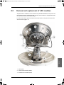
8.5 Removal and replacement of the ACU .........................................................8-18
8.6 Removal and replacement of ADU modules ............................................8-19
8.7 Troubleshooting .............................................................................................................8-22
8.7.1 Overview ...............................................................................................................................8-22
8.7.2 Event list for troubleshooting ....................................................................................8-22
8.7.3 Diagnostics report for troubleshooting .................................................................8-22
8.8 Frequently asked questions ..................................................................................8-23
8.8.1 Overview ...............................................................................................................................8-23
8.8.2 The questions ....................................................................................................................8-24
8.9 To return units for repair ........................................................................................8-35
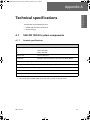
Appendix A Technical specifications
A.1 SAILOR 100 GX system components ................................................................A-1
A.1.1 General specifications .......................................................................................................A-1
A.1.2 ADU ...........................................................................................................................................A-2
A.1.3 ACU ............................................................................................................................................A-4
A.1.4 GMU ..........................................................................................................................................A-5
A.1.5 Patents ..................................................................................................................................A-5
SAILOR100GX-IM-98-141779.book Page x Wednesday, February 22, 2017 12:30 PM

Table of contents
98-141779-C xi
A.2 Outline drawings ...............................................................................................................A-6
A.2.1 ADU ...........................................................................................................................................A-6
A.2.2 ACU ............................................................................................................................................A-7
A.2.3 Modem .....................................................................................................................................A-8
A.2.4 N-connector interface on the ADU .........................................................................A-10
Appendix B Ground and RF protection
B.1 Why is a ground connection required? ............................................................B-1
B.1.1 Safety ........................................................................................................................................B-1
B.1.2 ESD Protection .....................................................................................................................B-1
B.2 Recommendations ...........................................................................................................B-2
B.2.1 To ground the ACU ............................................................................................................B-2
B.2.2 To ground the ADU ............................................................................................................B-3
B.3 Alternative ground for steel hulls ........................................................................B-4
B.3.1 To ground the ACU ............................................................................................................B-4
B.3.2 To ground the ADU ............................................................................................................B-4
B.4 Alternative ground for aluminum hulls ...........................................................B-6
B.4.1 To ground the ACU ............................................................................................................B-6
B.4.2 To ground the ADU ............................................................................................................B-6
B.5 Alternative ground for fiber glass hulls ...........................................................B-7
B.5.1 To ground the ACU ............................................................................................................B-7
B.5.2 To ground the ADU ............................................................................................................B-7
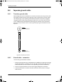
B.6 Separate ground cable ..................................................................................................B-8
B.6.1 To make a ground cable ...................................................................................................B-8
B.6.2 Ground cable - connection .............................................................................................B-8
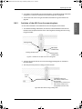
B.6.3 Isolation of the ADU from the mounting base .....................................................B-9
B.7 RF interference ................................................................................................................B-10
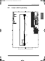
B.8 Jumper cable for grounding ...................................................................................B-11
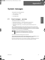
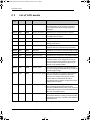
Appendix C System messages
C.1 Event messages – overview ......................................................................................C-1
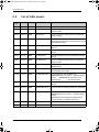
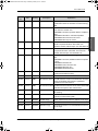
C.2 List of ADU events ...........................................................................................................C-2
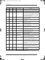
C.3 List of ACU events ...........................................................................................................C-7
SAILOR100GX-IM-98-141779.book Page xi Wednesday, February 22, 2017 12:30 PM

Table of contents
xii 98-141779-C
Appendix D Command line interface
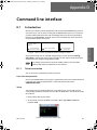
D.1 Introduction ........................................................................................................................ D-1
D.1.1 Telnet connection ............................................................................................................. D-1
D.1.2 Help ........................................................................................................................................... D-2
D.1.3 Conventions ......................................................................................................................... D-2
D.2 Supported commands ................................................................................................ D-2
D.2.1 config ....................................................................................................................................... D-3
D.2.2 demo ........................................................................................................................................ D-3
D.2.3 dual_antenna ....................................................................................................................... D-3
D.2.4 exit ............................................................................................................................................ D-3
D.2.5 help ........................................................................................................................................... D-4
D.2.6 modem .................................................................................................................................... D-4
D.2.7 satellite .................................................................................................................................... D-5
D.2.8 status ........................................................................................................................................ D-7
D.2.9 system ..................................................................................................................................... D-8
D.2.10 track .......................................................................................................................................... D-8
D.2.11 zone .......................................................................................................................................... D-9
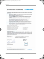
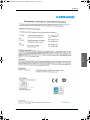
Appendix E Approvals
E.1 CE (R&TTE) ............................................................................................................................. E-1
Glossary ..............................................................................................................................................................Glossary-1
Index ....................................................................................................................................................................Index-1
SAILOR100GX-IM-98-141779.book Page xii Wednesday, February 22, 2017 12:30 PM

98-141779-C 1-1
Chapter 1
About this manual
About this manual 1
1.1 Intended readers
This is an installation and service manual for the SAILOR 100 GX system, intended for
installers of the system and service personnel. Personnel installing or servicing the system
must be properly trained and authorized by Cobham SATCOM. It is important that you
observe all safety requirements listed in the beginning of this manual, and install the system
according to the guidelines in this manual.
1.2 Manual overview
This manual has the following chapters:
• Introduction
• Installation
• Interfaces
• Power and startup
• Configuration
• Installation check
• Service
This manual has the following appendices:
• Technical specifications
• Ground and RF protection
• System messages
• Command line interface
• Approvals
1.3 Software version
This manual is intended for SAILOR 100 GX with software version 1.57 (ADU and
ACU). The modem software version is shown in the modem web interface.
SAILOR100GX-IM-98-141779.book Page 1 Wednesday, February 22, 2017 12:30 PM

Typography
1-2 Chapter 1: About this manual 98-141779-C
1.4 Typography
In this manual, typography is used as indicated below:
Bold is used for the following purposes:
•To emphasize words.
Example: “Do not touch the antenna”.
• To indicate what the user should select in the user interface.
Example: “Select SETTINGS > LAN”.
Italic is used to emphasize the paragraph title in cross-references.
Example: “For further information, see To connect cables on page...”.
1.5 Precautions
Text marked with “Warning”, “Caution”, “Note” or “Important” show the following type of
data:
• Warning: A Warning is an operation or maintenance procedure that, if not obeyed, can
cause injury or death.
• Caution: A Caution is an operation or maintenance procedure that, if not obeyed, can
cause damage to the equipment.
• Note: A Note gives information to help the reader.
• Important: A text marked Important gives information that is important to the user,
e.g. to make the system work properly. This text does not concern damage on
equipment or personal safety.
All personnel who operate equipment or do maintenance as specified in this manual must
know and follow the safety precautions. The warnings and cautions that follow apply to all
parts of this manual.
WARNING! Before using any material, refer to the
manufacturers’ material safety data sheets for safety
information. Some materials can be dangerous.
CAUTION! Do not use materials that are not
equivalent to materials specified by Thrane & Thrane.
Materials that are not equivalent can cause damage to
the equipment.
CAUTION! The system contains items that are
electrostatic discharge sensitive. Use approved industry
precautions to keep the risk of damage to a minimum
when you touch, remove or insert parts or assemblies.
SAILOR100GX-IM-98-141779.book Page 2 Wednesday, February 22, 2017 12:30 PM

98-141779-C 2-1
Chapter 2
Introduction
Introduction 2
This chapter has the following sections:
• SAILOR 100 GX system
• Part numbers and options
2.1 SAILOR 100 GX system
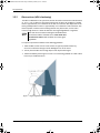
2.1.1 Overview
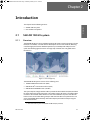
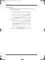
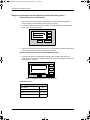
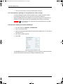
The SAILOR 100 GX is a unique stabilized maritime GX antenna system operating in the Ka-
band (19.2 to 30 GHz). It is used with the Global Xpress service from Inmarsat, delivering
consistent high-performance download speeds of up to 50 Mbps and 5 Mbps over the
uplink. The following figure shows the coverage map of the GX service at global service
introduction.
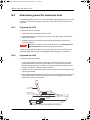
The SAILOR 100 GX system consists of the following units:
• SAILOR 7009C Above Deck Unit (ADU)
• SAILOR 7016C
1
Antenna Control Unit (ACU)
• SAILOR 7023A GX Modem Unit (modem)
The system requires a single 50 Ohm cable to provide the Above Deck Unit (ADU) with both
DC power, data and control information. The modem requires AC power. The radome does
not have to be removed neither before nor after the installation. To protect the ADU the
built-in motors act as brakes during transport and when the ADU is not powered. You can
access the SAILOR 100 GX remotely and make in-depth performance analysis using the
built-in web interface.
Figure 2-1: GX coverage map
1. Some antennas may have the SAILOR 7016B ACU (DC powered).
SAILOR100GX-IM-98-141779.book Page 1 Wednesday, February 22, 2017 12:30 PM

SAILOR 100 GX system
2-2 Chapter 2: Introduction 98-141779-C
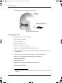
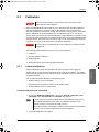
The following figure shows the SAILOR 100 GX system.
SAILOR 100 GX features
Single 50 Ohm coax cable for the ADU.
One-Touch Commissioning.
Gyro-free operation.
SNMP and syslog support.
Secure connection, HTTPS and SSH.
Remote access using SAILOR FleetBroadband over WAN.
Remote or local simultaneous software update of the GMU, ADU and ACU via PC and
Internet browser.
Full remote control and troubleshooting with built-in test equipment (BITE).
ACU with 4 x LAN, NMEA 0183, NMEA 2000, RS-232 and RS-422.
Global RF configuration.
ACU with AC power
1
GMU with 8+2 LAN, RS-232 and RS-422 and I/O connector.
No scheduled maintenance.
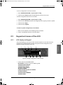
Figure 2-2: ADU, ACU and GMU
Above Deck
Unit (ADU)
Antenna Control Unit (ACU)
GX Modem Unit (GMU)
1. Some ACUs are DC powered. Start up voltage: 22 VDC guaranteed, operating range: 20
–32VDC.
SAILOR100GX-IM-98-141779.book Page 2 Wednesday, February 22, 2017 12:30 PM

SAILOR 100 GX system
98-141779-C Chapter 2: Introduction 2-3
Introduction
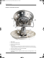
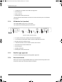
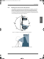
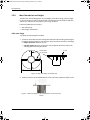
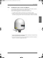
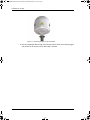
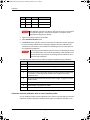
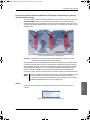
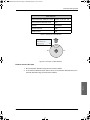
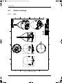
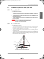
2.1.2 Above Deck Unit (ADU)
The SAILOR 100 GX ADU is a 103 cm stabilized tracking antenna, consisting of a suspended
antenna with a standard global RF configuration. It is stabilized by heavy duty vibration
dampers in 3-axis (plus skew) and can be used in environments with elevations of -25° to +
125°. The ADU weighs 126 kg and is powered by the ACU. The ADU is protected by a
radome.
All communication between the ADU and the ACU passes through a single standard
50 Ohm cable (with N connector) through the rotary joint. No cable work is required inside
the radome.
Figure 2-3: Above Deck Unit (ADU)
SAILOR100GX-IM-98-141779.book Page 3 Wednesday, February 22, 2017 12:30 PM

SAILOR 100 GX system
2-4 Chapter 2: Introduction 98-141779-C
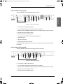
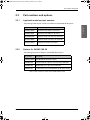
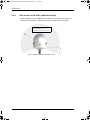
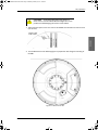
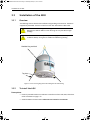
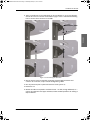
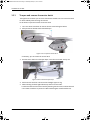
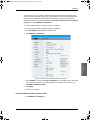
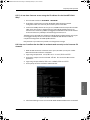
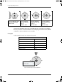
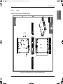
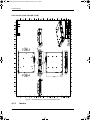
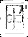
Modules in the SAILOR 100 GX ADU
1. GNSS module.
2. VSAT Interface Module (VIM).
3. Pedestal Control Module (PCM).
4. Service switch.
In switch-off position the Motor Driver modules and the BUC are turned off for safe
conditions during service and repair. The switch must be set to on for normal operation.
5. Motor Driver Module for cross elevation (DDM/SMD).
6. Cross elevation motor and encoder.
7. Zero Reference Module (x3) (ZRM) (not visible on photo), (2 in the figure above, 1 in the
figure below).
Figure 2-4: Above Deck Unit modules 1/2
SAILOR100GX-IM-98-141779.book Page 4 Wednesday, February 22, 2017 12:30 PM
Page is loading ...
Page is loading ...
Page is loading ...
Page is loading ...
Page is loading ...
Page is loading ...
Page is loading ...
Page is loading ...
Page is loading ...
Page is loading ...
Page is loading ...
Page is loading ...
Page is loading ...
Page is loading ...
Page is loading ...
Page is loading ...
Page is loading ...
Page is loading ...
Page is loading ...
Page is loading ...
Page is loading ...
Page is loading ...
Page is loading ...
Page is loading ...
Page is loading ...
Page is loading ...
Page is loading ...
Page is loading ...
Page is loading ...
Page is loading ...
Page is loading ...
Page is loading ...
Page is loading ...
Page is loading ...
Page is loading ...
Page is loading ...
Page is loading ...
Page is loading ...
Page is loading ...
Page is loading ...
Page is loading ...
Page is loading ...
Page is loading ...
Page is loading ...
Page is loading ...
Page is loading ...
Page is loading ...
Page is loading ...
Page is loading ...
Page is loading ...
Page is loading ...
Page is loading ...
Page is loading ...
Page is loading ...
Page is loading ...
Page is loading ...
Page is loading ...
Page is loading ...
Page is loading ...
Page is loading ...
Page is loading ...
Page is loading ...
Page is loading ...
Page is loading ...
Page is loading ...
Page is loading ...
Page is loading ...
Page is loading ...
Page is loading ...
Page is loading ...
Page is loading ...
Page is loading ...
Page is loading ...
Page is loading ...
Page is loading ...
Page is loading ...
Page is loading ...
Page is loading ...
Page is loading ...
Page is loading ...
Page is loading ...
Page is loading ...
Page is loading ...
Page is loading ...
Page is loading ...
Page is loading ...
Page is loading ...
Page is loading ...
Page is loading ...
Page is loading ...
Page is loading ...
Page is loading ...
Page is loading ...
Page is loading ...
Page is loading ...
Page is loading ...
Page is loading ...
Page is loading ...
Page is loading ...
Page is loading ...
Page is loading ...
Page is loading ...
Page is loading ...
Page is loading ...
Page is loading ...
Page is loading ...
Page is loading ...
Page is loading ...
Page is loading ...
Page is loading ...
Page is loading ...
Page is loading ...
Page is loading ...
Page is loading ...
Page is loading ...
Page is loading ...
Page is loading ...
Page is loading ...
Page is loading ...
Page is loading ...
Page is loading ...
Page is loading ...
Page is loading ...
Page is loading ...
Page is loading ...
Page is loading ...
Page is loading ...
Page is loading ...
Page is loading ...
Page is loading ...
Page is loading ...
Page is loading ...
Page is loading ...
Page is loading ...
Page is loading ...
Page is loading ...
Page is loading ...
Page is loading ...
Page is loading ...
Page is loading ...
Page is loading ...
Page is loading ...
Page is loading ...
Page is loading ...
Page is loading ...
Page is loading ...
Page is loading ...
Page is loading ...
Page is loading ...
Page is loading ...
Page is loading ...
Page is loading ...
Page is loading ...
Page is loading ...
Page is loading ...
Page is loading ...
Page is loading ...
Page is loading ...
Page is loading ...
Page is loading ...
Page is loading ...
Page is loading ...
Page is loading ...
Page is loading ...
Page is loading ...
Page is loading ...
Page is loading ...
Page is loading ...
Page is loading ...
Page is loading ...
Page is loading ...
Page is loading ...
Page is loading ...
Page is loading ...
Page is loading ...
Page is loading ...
Page is loading ...
Page is loading ...
Page is loading ...
Page is loading ...
Page is loading ...
Page is loading ...
Page is loading ...
Page is loading ...
Page is loading ...
Page is loading ...
Page is loading ...
-
 1
1
-
 2
2
-
 3
3
-
 4
4
-
 5
5
-
 6
6
-
 7
7
-
 8
8
-
 9
9
-
 10
10
-
 11
11
-
 12
12
-
 13
13
-
 14
14
-
 15
15
-
 16
16
-
 17
17
-
 18
18
-
 19
19
-
 20
20
-
 21
21
-
 22
22
-
 23
23
-
 24
24
-
 25
25
-
 26
26
-
 27
27
-
 28
28
-
 29
29
-
 30
30
-
 31
31
-
 32
32
-
 33
33
-
 34
34
-
 35
35
-
 36
36
-
 37
37
-
 38
38
-
 39
39
-
 40
40
-
 41
41
-
 42
42
-
 43
43
-
 44
44
-
 45
45
-
 46
46
-
 47
47
-
 48
48
-
 49
49
-
 50
50
-
 51
51
-
 52
52
-
 53
53
-
 54
54
-
 55
55
-
 56
56
-
 57
57
-
 58
58
-
 59
59
-
 60
60
-
 61
61
-
 62
62
-
 63
63
-
 64
64
-
 65
65
-
 66
66
-
 67
67
-
 68
68
-
 69
69
-
 70
70
-
 71
71
-
 72
72
-
 73
73
-
 74
74
-
 75
75
-
 76
76
-
 77
77
-
 78
78
-
 79
79
-
 80
80
-
 81
81
-
 82
82
-
 83
83
-
 84
84
-
 85
85
-
 86
86
-
 87
87
-
 88
88
-
 89
89
-
 90
90
-
 91
91
-
 92
92
-
 93
93
-
 94
94
-
 95
95
-
 96
96
-
 97
97
-
 98
98
-
 99
99
-
 100
100
-
 101
101
-
 102
102
-
 103
103
-
 104
104
-
 105
105
-
 106
106
-
 107
107
-
 108
108
-
 109
109
-
 110
110
-
 111
111
-
 112
112
-
 113
113
-
 114
114
-
 115
115
-
 116
116
-
 117
117
-
 118
118
-
 119
119
-
 120
120
-
 121
121
-
 122
122
-
 123
123
-
 124
124
-
 125
125
-
 126
126
-
 127
127
-
 128
128
-
 129
129
-
 130
130
-
 131
131
-
 132
132
-
 133
133
-
 134
134
-
 135
135
-
 136
136
-
 137
137
-
 138
138
-
 139
139
-
 140
140
-
 141
141
-
 142
142
-
 143
143
-
 144
144
-
 145
145
-
 146
146
-
 147
147
-
 148
148
-
 149
149
-
 150
150
-
 151
151
-
 152
152
-
 153
153
-
 154
154
-
 155
155
-
 156
156
-
 157
157
-
 158
158
-
 159
159
-
 160
160
-
 161
161
-
 162
162
-
 163
163
-
 164
164
-
 165
165
-
 166
166
-
 167
167
-
 168
168
-
 169
169
-
 170
170
-
 171
171
-
 172
172
-
 173
173
-
 174
174
-
 175
175
-
 176
176
-
 177
177
-
 178
178
-
 179
179
-
 180
180
-
 181
181
-
 182
182
-
 183
183
-
 184
184
-
 185
185
-
 186
186
-
 187
187
-
 188
188
-
 189
189
-
 190
190
-
 191
191
-
 192
192
-
 193
193
-
 194
194
-
 195
195
-
 196
196
-
 197
197
-
 198
198
-
 199
199
-
 200
200
-
 201
201
-
 202
202
-
 203
203
-
 204
204
-
 205
205
-
 206
206
-
 207
207


COBHAM SAILOR 100 GX Installation guide
- Category
- Television antennas
- Type
- Installation guide
Ask a question and I''ll find the answer in the document
Finding information in a document is now easier with AI
Related papers
-
COBHAM EXPLORER 7100GX Installation and User Manual
-
-
-
-
-
-
-
-
-
Other documents
-
 Thrane&Thrane Sailor 100 Satellite TV User manual
-
 KVH TracPhone Fleet One, FB250 & FB150 Installation guide
-
DeLOCK 93169 Datasheet
-
 Thrane&Thrane SAILOR 900 VSAT System Installation & Service Manual
-
LG F-1208V5W Owner's manual
-
Sailor 250 FleetBroadband Installation guide
-
 Thrane&Thrane TT-3057A Installation guide
-
Dahua ITARD-024MA-H Quick start guide
-
 KVH SAILOR 4300 Installation guide
-
 iDirect Evolution X3 Installation And Safety Manual


