Page is loading ...

DRAWMER
CONTENTS
Warranty
Safety Consideration
Radio Frequencies Statement
Chapter 1 - Introduction
Introduction
Installation
Audio Connection
Power Connection
Portable Applinace Testing
Typical Connection Guide
Chapter 2 - Control Description
Contol Description
Example Wiring Methods
Chapter 3 - General Information
If a fault develops
Contacting Drawmer
Specification
Block Diagram
. . . . . . . . . . . . . . . . . . . . . . . . . . . 3
. . . . . . . . . . . . . . . . . . 3
. . . . . . . . . . . 3
. . . . . . . . . . . . . . . . . . . . . . . . 4
. . . . . . . . . . . . . . . . . . . . . . . . . 6
. . . . . . . . . . . . . . . . . . . . . 6
. . . . . . . . . . . . . . . 7
. . . . . . . . . . . . . . . . . . . . . 7
. . . . . . . . . . . . . . . . 8
. . . . . . . . . . . . . . . . . . . . . 9
. . . . . . . . . . . . . . . 11
. . . . . . . . . . . . . . . . . . . . 15
. . . . . . . . . . . . . . . . . . .15
. . . . . . . . . . . . . . . . . . . . . . . 15
. . . . . . . . . . . . . . . . . . . . . . 16
MPA-90
MONITOR POWER AMPLIFIER

2
DRAWMER

3
MPA-90 - Monitor Power Amplifier
COPYRIGHT
This manual is copyrighted © 2016 by Drawmer Electronics Ltd. With all rights reserved. Under copyright
laws, no part of this publication may be reproduced, transmitted, stored in a retrieval system or translated
into any language in any form by any means, mechanical, optical, electronic, recording, or otherwise,
without the written permission of Drawmer Electronics Ltd.
Drawmer Electronics Ltd., warrants the Drawmer MPA-90 Monitor
Power Amplifier to conform substantially to the specifications of this
manual for a period of one year from the original date of purchase
when used in accordance with the specifications detailed in this
manual. In the case of a valid warranty claim, your sole and exclusive
remedy and Drawmer’s entire liability under any theory of liability will
be to, at Drawmer’s discretion, repair or replace the product without
charge, or, if not possible, to refund the purchase price to you. This
warranty is not transferable. It applies only to the original purchaser
of the product.
For warranty service please call your local Drawmer dealer.
Alternatively call Drawmer Electronics Ltd. at +44 (0)1709 527574.
Then ship the defective product, with transportation and insurance
charges pre-paid, to Drawmer Electronics Ltd., Coleman Street,
Parkgate, Rotherham, S62 6EL UK. Write the RA number in large
letters in a prominent position on the shipping box. Enclose your
name, address, telephone number, copy of the original sales invoice
and a detailed description of the problem. Drawmer will not accept
responsibility for loss or damage during transit.
This warranty is void if the product has been damaged by misuse,
modification, unauthorised repair or installed with other equipment
that proved to be faulty.
THIS WARRANTY IS IN LIEU OF ALL W ARRANTIES, WHETHER
ORAL OR WRITTEN, EXPRESSED, IMPLIED OR STATUTORY.
DRAWMER MAKES NO OTHER WARRANTY EITHER
EXPRESS OR IMPLIED, INCLUDING, WITHOUT LIMITATION,
ANY IMPLIED WARRANTIES OF MERCHANTABILITY, FITNESS
FOR A PARTICULAR PURPOSE, OR NON-INFRINGEMENT.
PURCHASER’S SOLE AND EXCLUSIVE REMEDY UNDER THIS
WARRANTY SHALL BE REPAIR OR REPLACEMENT AS
SPECIFIED HEREIN.
IN NO EV ENT W ILL D RAW ME R ELE CTRONICS LTD. B E LIA BLE
FOR ANY DIRECT, INDIRECT, SPECIAL, INCIDENTAL OR
CONSEQUENTIAL DAMAGES RESULTING FROM ANY
DEFECT IN THE PRODUCT, INCLUDING LOST PROFITS,
DAMAGE TO PROPERTY, AND, TO THE EXTENT PERMITTED
BY LAW, DAMAGE FOR PERSONAL INJURY, EVEN IF
DRAWMER HAS BEEN ADVISED OF THE POSSIBILITY OF
SUCH DAMAGES.
Some states and specific countries do not allow the exclusion of
implied warranties or limitations on how long an implied warranty may
last, so the above limitations may not apply to you. This warranty gives
you specific legal rights. You may have additional rights that vary from
state to state, and country to country.
For the USA
FEDERAL COMMUNICATIONS COMMISSION RADIO
FREQUENCY INTERFERENCE STATEMENT
This equipment has been tested and found to comply with the limits
for a Class B digital device, pursuant to Part 15 of the FCC Rules.
These limits are designed to provide reasonable protection against
harmful interference in a residential installation. This equipment
generates, uses and can radiate radio frequency energy and, if not
installed and used in accordance with the instructions, may cause
harmful interference to radio communications. However, there is no
guarantee that interference will not occur in a particular installation.
If this equipment does cause interference to radio or television
reception, which can be determined by turning the equipment off an
on, then the user is encouraged to try to correct the interference by
one or more of the following measures:
Re-orient or relocate the receiving antenna.
Increase the separation between the equipment and the receiver.
Connect the equipment into an outlet on a circuit different from that
to which the receiver is connected.
Consult the dealer or an experienced radio/TV technician for help.
Unauthorised changes or modification to this system can void the
users’ authority to operate this equipment.
This equipment requires shielded interface cables in order to meet
FCC class B limit.
For Canada
CLASS B NOTICE
This digital apparatus does not exceed the Class B limits for radio
noise emissions set out in the Radio Interference Regulations of the
Canadian Department of Communications.
CLASSE B AVIS
Cet appareil numérique ne dépasse pas les limites de la classe B au
niveau des émissions de bruits radioélectriques fixés dans le
Règlement des signaux parasites par le ministère Canadien des
Communications.
SAFETY CONSIDERAT
IONS
CAUTION - SERVICING
DO NOT OPEN. REFER ALL SERVICING TO QUALIFIED SERVICE PERSONNEL.
WARNING
TO REDUCE RISK OF FIRE/ELECTRIC SHOCK DO NOT EXPOSE THIS EQUIPMENT TO MOISTURE.
WARNING
DO NOT ATTEMPT TO CHANGE OR TAMPER WITH THE SUPPLIED MAINS CABLES.
WARNING
THE FUSE IN THE INLET HAS BEEN SET TO A RATING THAT ENSURES IT WILL BLOW BEFORE THE
INTERNAL FUSE IF THE AMPLIFIER IS DRIVEN AT CLIPPING LEVELS FOR ANY SIGNIFICANT LENGTH
OF TIME. THIS IS TO PREVENT THE AMPLIFIER AND/OR SPEAKERS FROM BEING DAMAGED. TO
REDUCE THE RISK OF FIRE REPLACE THE MAINS FUSES ONLY WITH A FUSE THAT CONFORMS TO
IEC127-2. 250 VOLT WORKING, TIME DELAY TYPE AND BODY SIZE OF 20mm x 5mm. THE MAINS
INPUT FUSE MUST BE RAT ED AT T1.6A at 115V and T800mA at 230V.
ONE YEAR LIMITED WARRANTY
In the interests of product development, Drawmer reserve the right to modify
or improve specifications of this product at any time, without prior notice.

4
DRAWMER
CHAPTER 1
As the perfect partner for Drawmer MC series of monitor controllers, the MPA-90 is
a high performance Class D Stereo Power amplifier delivering 90W per channel
into 4 Ohms (50W per channel into 8 Ohms) or, when in mono, acts as a 180W into
8ohms Monoblock.
The MPA-90 been designed to complement the Drawmer MC1.1 Monitor Pre-
Amplifier but functions just as well if partnered with the MC2.1 or MC3.1, or indeed,
any other pre-amplifier. It is perfect for powering passive monitors in the studio,
such as the classic Yamaha NS10 or Auratone C5 types, for example, but is just as
capable as part of your home hi-fi system. Pairing a MPA-90 with a MC1.1 and your
favourite turntable and speakers would make a superb system to listen to your
vinyl collection.
Features include thermal, overload and power up/power down protection and an
output clipping indicator. In addition, it has switchable balanced XLR and unbalanced
Phono inputs to suit your system.
One very smart feature of the MPA-90 is that, in addition to standard Stereo Power
Amplifier operation, with the flick of a switch to set the MPA-90 to mono mode, and
with a little speaker cable rewiring, it functions as a 180W into 8ohms Monoblock,
allowing the system to operate in bi-amped or bridged modes.
MPA-90
Monitor Power Amplifier

5
MPA-90 - Monitor Power Amplifier
Drawmer MPA-90 Monitor Power Amp Features at a Glance:
90+90Wrms into 4 Ohms@1%THD.
50+50Wrms into 8 Ohms@1%THD.
1x180W into 8 Ohms bridged mode.
Stereo/Mono switch to use as a Stereo amplifier or as a
Monoblock in Bridged or Bi-Amp Modes.
Switchable balanced Neutrik XLR and unbalanced Phono
inputs.
Efficient, low heat design with Low Power Consumption.
Consumes only 10W of power when idling and only 0.7W
when in standby mode.
Thermal, overload and power up/power down protection.
Standby, fault and clip indicators
Rugged steel chassis and stylish brushed aluminium cover.
Can be stacked and is rack mountable (with the MCB 2U
mounting kit).
Dimensions: L 276mm x W 215mm x H 81mm.

6
DRAWMER
INSTALLATION
The MPA-90 is a free standing, desktop unit, with indication on the front panel and
all other inputs and outputs on the rear. Multiple units can be stacked whilst sitting
on the desk, however, the MPA can be screwed to the desk or into a standard 19”
rack (using a 2U mounting kit).
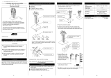
Screwing the MPA-90 to a desk.
Rather than having the MPA-90 free standing it
can be fastened down to a desk by utilising the
holes that hold the rubber feet to the underside.
Drill four holes into the desk, at 4mm in
diameter and to the dimensions as shown in
the diagram. (Note that the diagram is viewed
from above).
Pushing four screws through the under-side of
the desk screw the MPA, including the rubber
feet, to the panel to secure. The screws should
be M3 and have a length of 14mm plus the
thickness of the panel.
AUDIO CONNECTIONS
• Interference:
If the unit is to be used where it maybe exposed to high levels of disturbance
such as found close to a TV or radio transmitter, we advise that the unit is
operated in a balanced configuration. The screens of the signal cables should
be connected to the chassis connection on the XLR connector as opposed to
connecting to pin1. The MPA-90 conforms to the EMC standards.
• Ground Loops:
If ground loop problems are encountered, never disconnect the mains earth,
but instead, try disconnecting the signal screen on one end of each of the
cables connecting the outputs of the MPA-90 to the patchbay. If such measures
are necessary, balanced operation is recommended.

7
MPA-90 - Monitor Power Amplifier
The MPA-90 unit will be supplied with a power cable suitable for domestic power
outlets in your country. For your own safety, it is important that you use this cable to
connect to the mains supply earth. The cable must not be tampered with or modified.
The power supply socket has an integral fuse drawer containing the power fuse of
the same value, to suit the mains voltage for which the unit has been supplied.
Removal of the drawer is only possible with the power cord removed. The fuse
should never blow under normal operation. If the fuse is suspected of having blown,
then a fault will have occurred and this fault condition should be inspected by a
qualified service engineer. When replacing the fuse, always comply with the Safety
Instructions.
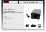
If the unit is to be used with a mains
input operating voltage different to
that for which the unit is supplied,
the following procedure must be
carried out by a technically
competent person:
1: Disconnect the unit from the
mains and cable.
2: Using a No.1 size pozidrive
screwdriver, remove the eight
screws that retain the top cover.
For conversion to 230Volt AC
(previously set to 115Volt AC).....
3a. remove the jumper across
the S101 socket
3b. Replace the Radial T PCB
mount fuse at FH1 with a T1AL
of the same type.
3c. Exchange the T1.6A fuse
below the mains socket for a
similar type rated at T800mA
For conversion to 115Volt AC
(previously set to 230Volt AC).....
4a. Add a 5.08mm Pitch jumper across the S101
socket
4b. Replace the Radial T PCB mount fuse at FH1
with a T2AL of the same type.
4c. Exchange the T800mA fuse below the mains
socket for a similar type rated at T1.6A
In all cases:
5: Replace the top cover using the eight screws.
6: Reconnect to mains power source.
POWER CONNECTION
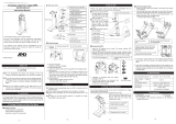
PORTABLE APPLIANCE TESTING
To undergo a Portable Appliance Testing procedure (commonly known as "PAT",
"PAT Inspection" or "PAT Testing") use any one of the screws that hold the feet to the
bottom of the unit. These screws connect directly to the chassis and provide the
earthing point. If required, the foot can be removed and the cavity probed, or the
screw can be replaced for something more suited to the job, such as a spade
terminal with a M3 thread.

8
DRAWMER
TYPICAL CONNECTION GUIDE

9
MPA-90 - Monitor Power Amplifier
CONTROL DESCRIPTION
POWER On / Standby
The unit has a soft on/off switch on the front panel. With the switch in the MPA is
active and the LED indication beneath lights. With the switch out the MPA is operating
in standby - the standby LED illuminates and the MPA draws 0.7 Watts of power.
INPUT XLR / RCA
The two LED’s illuminate to indicate which of the two inputs are in use, either XLR
or RCA, as determined by the switch on the rear panel (see ).
MODE Stereo / Mono
The two LED’s illuminate to indicate which mode the MPA is in - either Stereo or
Mono, as determined by the slide switch on the rear panel (see ).
STATUS Fault / Clip
Fault: This is illuminated is the MPA has detected an error via it’s built in sensors
these include:
Power shut down by over temperature - If the temperature inside the MPA should
pass the threshold of 100°C minimum to 110°C maximum (105°C typical) the MPA
will shut down for a few moments. The shutdown time is short but increases as the
unit heats up. As well as the illumination of the LED indication this protection mode
will be heard as very short interrupts to the sound.
Over voltage shutdown. - If the mains voltage exceeds the absolute maximum rated
level of ~ 90-132 / 180-264 VAC the MPA will momentarily shut down and the Fault
LED will illuminate. This protection mode will be heard as very short interrupts to
the sound.
In the event of a fault occurring the source of the problem should be repaired before
permanent damage to the system occurs.
Clip: W hen the input from the pre-amplifier reaches the level of -0.1dBu the clip
LED will illuminate. This is the point at which distortion is starting to occur at the
speaker output and therefore anything above this level will show a deterioration in
the audio quality. For the best audio quality you should operate the volume level so
that the maximum level only rarely illuminates the Clip LED.
CHAPTER 2
1
2
5
3
7
4

10
DRAWMER
INPUT XLR / RCA
The MPA has two inputs comprising balanced Neutrik XLR’s and unbalanced RCA’s
connectors. The switch above determines which is used, and this is shown on the
front panel .
THRU’ RCA
Whichever of the inputs is selected as the source is passed through to these
unbalanced RCA’s connectors. This allows the audio chain to continue and enables
the signal to be sent to an active sub woofer, or to a recording device, for example.
It also allows several MPA’s to be daisychained to create a whole network of
amplifiers to fill multiple rooms (see ‘Daisychaining’ p14). Note that the thru output
is not affected by the stereo/mono switch and so any one of these amplifiers within
this chain could be in mono, to operate as a monoblock, without affecting any
others.
MODE & WIRING Stereo / Mono
A slide switch selects the mode of the MPA-90, whether in standard STEREO mode
or in MONO, allowing the MPA to operate in Bridged mode as a monoblock. This is
indicated on the front panel ( ).
In Stereo mode the MPA-90 operates like any standard stereo amplifier, with a
power output of 90+90Wrms @ 4 Ohms, 50+50Wrms @ 8 Ohms.
Setting the switch to mono combines the power of the two channels into a single
output of 1 x 180Wrms @ 8 Ohms, however, note that only two binding posts are
used (see ). Also note that when in Mono mode the MPA-90 derives it’s signal
from the Left input only.
SPEAKER OUTPUTS L-/L+/R-/R+
The speaker outputs connectors are in the form of binding posts that can be wired
directly to the speaker terminals via bare wires through the hole and tightened, via
spade terminals, or via banana plugs.*
The diagrams on the following pages show some common wiring methods. Note
that when in bridged mono mode the R- provides the negative terminal and L+
provides the positive, the other terminals are not used.
*Due to European legislation the use of banana plugs is not permitted. Banana plugs should only be used
in the USA and Canada.
5
2
7
6
8
3
8

11
MPA-90 - Monitor Power Amplifier
POWER
The mains inlet, I.E.C., which also incorporates the internal mains fuse, can be
found on the rear of the unit. If a fuse should need replacing see section ‘Power
Connection’. A mains lead will have been provided with the MPA-90 to suit the
mains configuration for the country of your purchase. Please use this cable.
The power switch is located above the I.E.C. and is used to switch the unit on and
off. This is a hard boot switch (as opposed to a soft stand-by switch) and so when
in the off position the MPA-90 will draw no mains power.
Note that a timed relay protection circuit has been incorporated into the MPA-90 to
prevent bangs and other potentially harmful artifacts from occurring during power up
and power down.
9
EXAMPLE WIRING METHODS
STANDARD STEREO WIRING
90+90Wrms into 4 Ohms@1%THD

12
DRAWMER
STEREO BI-WIRING
90+90Wrms into 4 Ohms@1%THD
HORIZONTAL BI-AMPING (2 required)
180+180Wrms into 4 Ohms@1%THD

13
MPA-90 - Monitor Power Amplifier
VERTICALBI-AMPING (2 required)
180+180Wrms into 4 Ohms@1%THD
STEREO VIA MONOBLOCKS (2 required)
180+180Wrms into 8 Ohms@1%THD

14
DRAWMER
% THD Noise vs Power
DAISYCHAINING
The Thru’ output on the rear of the unit allows several MPA-90’s to be linked and
controlled by one single volume control.

15
MPA-90 - Monitor Power Amplifier
CHAPTER 3
MPA-90 8ohm MPA-90 4ohm
T HD @ 1W 0.004 0.005
POWER @ 1% THD 50 + 50 Wrms 90 + 90 Wrms
BRIDGE D PO W ER @ 1% T HD 180W rms N/A
GAIN 28.5dB 28.5dB
Balanced CROSSTALK @ 0dBu 1kHz <85dB <85dB
Phono CROSSTALK @ 0dBu 1kHz <79dB <79dB
Input voltage for max unclipped output 775mv (0dBu) 775mv (0dBu)
Clip Led Threshold -0.1 dBu -0.1 dBu
Frequency Response (+/-0.25dBu ) 20Hz-20kHz 20Hz-20kHz
Output Impedance 3milli ohms 3milli ohms
For warranty service please call Drawmer Electronics
Ltd. or their nearest authorised service facility, giving
full details of the difficulty. A list of all main dealers
can be found on the Drawmer webpages. On receipt
of this information, service or shipping instructions
will be forwarded to you.
No equipment should be returned under the warranty
without prior consent from Drawmer or their authorised
representative.
For service claims under the warranty agreement a
service Returns Authorisation (RA) number will be
issued.
Write this RA number in large letters in a prominent
position on the shipping box. Enclose your name,
address, telephone number, copy of the original sales
invoice and a detailed description of the problem.
Authorised returns should be prepaid and must be
insured.
All Drawmer products are packaged in specially
designed containers for protection. If the unit is to
be returned, the original container must be used. If
this container is not available, then the equipment
should be packaged in substantial shock-proof
material, capable of withstanding the handling for
the transit.
CONTACTING DRAWMER
We will be pleased to answer all application questions
to enhance your usage of Drawmer equipment.
Please address correspondence to:
DRAWMER Electronics LTD
Coleman Street
Parkgate
Rotherham
South Yorkshire
S62 6EL
United Kingdom
Telephone: +44 (0) 1709 527574
Fax: +44 (0) 1709 526871
Contact via E-mail: [email protected]
Further information on all Drawmer products,
dealers, Authorised service departments and other
contact information can be found on our website:
www.drawmer.com
MPA-90 GENERAL INFORMATION
IF A FAULT DEVELOPS
POWER REQUIREMENTS
Nominal rating: ~ 115 / 230 VAC
Absolute min/max:~ 90-132 / 180-264 VAC
45-63Hz
POWER CONSUMPTION
@ Idle 10W max at 230VAC, with
Maximum load for Energy
Star compliance
@ Standby 700mW typical
SPECIFICATION
FUSE
20mm x 5mm, Class 3 Slo-Blo,
250Volt working. Conforming to IEC 127-2
T1.6A @ 115V , T800mA @ 230V
Note: the fuse in the inlet has been set to a rating
that ensures it will blow before the internal fuse if the
amplifier is driven at clipping levels for any significant
length of time. This is to prevent the amplifier and/or
speakers from being damaged.
CASE SIZE
276mm(D) x 215mm(W) x 81mm(H with feet)
WEIGHT 2.2kg

16
DRAWMER
Ref:1v00A 05-07-16
BLOCK DIAGRAM
/