Page is loading ...

SIMPLICITY MICRO INSTRUCTION MANUAL
Approved Document No: GLT.MAN-129
Issue : 1.05 Author: NRPJ Date: 26/11/2013
ANALOGUE ADDRESSABLE FIRE ALARM PANEL
INSTRUCTION MANUAL

SIMPLICITY MICRO INSTRUCTION MANUAL
Approved Document No: GLT.MAN-129 PAGE 1
Issue : 1.05 Author: NRPJ Date: 26/11/2013
INDEX
INDEX ........................................................................................................................................ 1
INTRODUCTION ....................................................................................................................... 2
MAINS & BATTERY ................................................................................................................... 3
CONNECTING THE MAINS. ................................................................................................. 3
CONNECTING THE BATTERIES ......................................................................................... 3
DETECTORS & SOUNDERS .................................................................................................... 4
WIRING THE DETECTORS, SOUNDERS & CALL POINTS. .............................................. 4
PRE-COMMISSIONING CABLE CHECKS ........................................................................... 4
SETTING THE DEVICE ADDRESS ...................................................................................... 5
ADDRESS DIP SWITCH SETTINGS & ZONE ALLOCATION ............................................. 5
SPECIFIC DEVICE WIRING INSTRUCTIONS ..................................................................... 6
DISPLAY & CONTROLS ........................................................................................................... 6
DISPLAY & CONTROLS ........................................................................................................... 7
DISPLAY ................................................................................................................................ 7
CONTROLS ........................................................................................................................... 8
ENABLING THE CONTROLS. .......................................................................................... 8
ENTERING CONFIGURATION MENU 1 (USER MENU) ................................................. 8
ENTERING CONFIGURATION MENU 2 (ENGINEER MENU) ........................................ 8
CONFIGURING THE SIMPLICITY FIRE ALARM PANEL ........................................................ 9
CONFIGURING THE LOOPS ............................................................................................... 9
SETTING TIME AND DATE ................................................................................................ 10
SETTING A CUSTOM BANNER ......................................................................................... 10
VIEWING DEVICE STATUS .................................................................................................... 11
LOCATE OR VERIFY A DEVICE ........................................................................................ 12
USING THE EVENT LOG ................................................................................................... 12
CHECKING SOFTWARE VERSION ................................................................................... 13
DISABLEMENT ........................................................................................................................ 14
ZONE DISABLEMENT ........................................................................................................ 14
TO PROGRAMME ZONE (OR SOUNDERS) AS DISABLED ............................................ 14
POINT DISABLEMENT ....................................................................................................... 15
VIEWING DISABLEMENTS ................................................................................................ 15
TO VIEW FROM THE DISABLEMENT SCREEN ........................................................... 15
TO VIEW FROM THE DEVICE STATUS SCREEN ....................................................... 15
TEST MODE ............................................................................................................................ 16
WHY USE TEST MODE ...................................................................................................... 16
TO PROGRAMME ZONE IN TEST MODE ......................................................................... 16
ALARM CONDITION & RESETTING AN ALARM ................................................................... 17
WHAT TO DO IN THE EVENT OF A FIRE. ........................................................................ 17
RESETTING FROM AN ALARM CONDITION .................................................................... 17
FAULT DISPLAY & FAULT-FINDING ..................................................................................... 18
FAULT FINDING.................................................................................................................. 18
POWER SUPPLY FAULTS ............................................................................................. 18
EARTH FAULTS ............................................................................................................. 19
LOOP CABLING FAULTS ............................................................................................... 19
DEVICE FAULTS ............................................................................................................ 20
MISSING DEVICE FAULTS ............................................................................................ 21
BATTERY CALCULATION ...................................................................................................... 22
SAMPLE CALCULATION .................................................................................................... 22
SPECIFICATIONS ................................................................................................................... 23
ELECTRICAL SPECIFICATIONS ....................................................................................... 23
ENCLOSURE SPECIFICATIONS ....................................................................................... 23
FUSE RATINGS .................................................................................................................. 23
SIMPLICITY MICRO CONFIGURATION & TESTING............................................................. 24
LOG BOOK .............................................................................................................................. 25
MAINTENANCE WORK ...................................................................................................... 25
FALSE ALARMS.................................................................................................................. 26
ALL OTHER EVENTS ......................................................................................................... 27

SIMPLICITY MICRO INSTRUCTION MANUAL
Approved Document No: GLT.MAN-129 PAGE 2
Issue : 1.05 Author: NRPJ Date: 26/11/2013
Introduction
The Simplicity Micro has been designed as an ideal fire alarm panel for
smaller premises. It is an analogue addressable system that is priced
competitively with traditional conventional fire alarm systems.
Being an addressable system, the panel will locate the exact cause of an
alarm, and each detector can be labelled with a 20 character description to
further improve user friendliness. An exact location is much more useful for
locating the cause of an alarm, rather than just a zone indication, which might
contain 15 or more detectors.
As the name suggests, the panel is based on the highly popular Simplicity
range of fire panels, and incorporates nearly all of their features.
Installation couldn`t be easier. Simply wire all the detectors, sounders and call
points to a single loop of cable. Give each device a unique address. Enter the
panels menu & select “configure the loop” option. Enter the detector location
descriptions. And the system is now up & running.

SIMPLICITY MICRO INSTRUCTION MANUAL
Approved Document No: GLT.MAN-129 PAGE 3
Issue : 1.05 Author: NRPJ Date: 26/11/2013
Mains & Battery
Connecting the mains.
The Mains supply to the FACP is fixed wiring, using Fire resisting 3-core
cable (Between 1 mm² and 2.5mm²) or a suitable 3-conductor system, fed
from an isolating double pole switch fused spur, fused at 3A. IT SHOULD
NOT BE CONNECTED THROUGH AN RCD. This should be secure from
unauthorised operation and be marked ‘FIRE ALARM: DO NOT SWITCH
OFF’. The supply must be exclusive to the Fire Panel. MAKE SURE ANY
SPARE ENTRY HOLES ARE COVERED WITH THE GROMMETS
PROVIDED
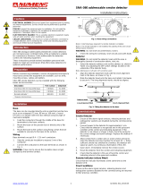
Connecting the batteries
The Simplicity Micro requires 2 x 12 V sealed lead acid (SLA) batteries
The two batteries are wired in series.
The +ve of one battery is connected to the red battery lead.
The –ve of the other battery is connected to the black battery lead.
The –ve of the first battery is connected to the +ve of the second battery using
the link wire supplied.
Although there are many sizes of suitable battery, the sizes the enclosure has
been designed for 12V 2Ah.
SLA BATTERY
12V / 2 Ah
TO PCB
2 x 2Ah Ba tteries
BATTERY
INTERC ONNEC TING
C ABLE
SLA BATTERY
12V / 2 Ah

SIMPLICITY MICRO INSTRUCTION MANUAL
Approved Document No: GLT.MAN-129 PAGE 4
Issue : 1.05 Author: NRPJ Date: 26/11/2013
Detectors & sounders
Wiring the detectors, sounders & call points.
The Simplicity micro comes with one addressable loop. Addressable detectors, addressable call points,
addressable loop powered sounders and several other interface units can be connected to these loops.
A MAXIMUM OF 32 DEVICES CAN BE CONNECTED TO THE LOOP.
I
O
H
I O
I
O
O
H
I
I
I
O
OOO
H
O
SIDE A + VE
SIDE A -VE
SIDE B + VE
SIDE B -VE
Loop Isolator Base
Sm oke Detector
Heat Detector
Call Point
Sounder
Pre-Commissioning Cable Checks
1. +ve in to +ve out less than 24 ohms
2. -ve in to -ve out less than 24 ohms (may need to temporarily disable isolators to measure)
3. +ve to –ve greater than 500k ohm
4. +ve to Earth greater than 1M ohm.
5. -ve to Earth greater than 1M ohm.
6. +ve to –ve less than 50 mV pickup (on AC & DC scales)

SIMPLICITY MICRO INSTRUCTION MANUAL
Approved Document No: GLT.MAN-129 PAGE 5
Issue : 1.05 Author: NRPJ Date: 26/11/2013
Setting the Device Address
Address DIP Switch Settings & Zone Allocation
Each device on the loop is given a different binary address. See table below for switch
settings.
ADDR SWITCHES
ADDR SWITCHES
1 2 3 4 5 6 7
1 2 3 4 5 6 7
0 =
n o t u s e d 17 =
OFF ON ON ON OFF ON ON
1 =
OFF ON ON ON ON ON ON 18 =
ON OFF ON ON OFF ON ON
2 =
ON OFF ON ON ON ON ON 19 =
OFF OFF ON ON OFF ON ON
3 =
OFF OFF ON ON ON ON ON 20 =
ON ON OFF ON OFF ON ON
4 =
ON ON OFF ON ON ON ON 21 =
OFF ON OFF ON OFF ON ON
5 =
OFF ON OFF ON ON ON ON 22 =
ON OFF OFF ON OFF ON ON
6 =
ON OFF OFF ON ON ON ON 23 =
OFF OFF OFF ON OFF ON ON
7 =
OFF OFF OFF ON ON ON ON 24 =
ON ON ON OFF OFF ON ON
8 =
ON ON ON OFF ON ON ON 25 =
OFF ON ON OFF OFF ON ON
9 =
OFF ON ON OFF ON ON ON 26 =
ON OFF ON OFF OFF ON ON
10 =
ON OFF ON OFF ON ON ON 27 =
OFF OFF ON OFF OFF ON ON
11 =
OFF OFF ON OFF ON ON ON 28 =
ON ON OFF OFF OFF ON ON
12 =
ON ON OFF OFF ON ON ON 29 =
OFF ON OFF OFF OFF ON ON
13 =
OFF ON OFF OFF ON ON ON 30 =
ON OFF OFF OFF OFF ON ON
14 =
ON OFF OFF OFF ON ON ON 31 =
OFF OFF OFF OFF OFF ON ON
15 =
OFF OFF OFF OFF ON ON ON 32 =
ON ON ON ON ON OFF ON
16 =
ON ON ON ON OFF ON ON 33-127 =
n o t u s e d
On the Simplicity Micro, the address given to a device will determine which zone it is
allocated to.
DEVICE ADDRESS ZONE
0 NOT USED
1 TO 8 ZONE 1
9 TO 16 ZONE 2
17 TO 24 ZONE 3
25 TO 32 ZONE 4
33 TO 127 NOT USED
Traditionally a building would be zoned to divide it into smaller sections to indicate
which section had the alarm. On an addressable system, the panel can give an exact
location, so the zone information is less useful.
1
7
65
43
2
8
ON
The address setting is binary, with the
ON position being binary 0 , and the
OFF position being binary 1. Switch 8
is not used for setting the address, but
sometimes has a device specific
function. (check instructions that come
with the device).
EG on sounder bases,
switch 8 MUST BE ON.
If you are not familiar with binary, use the table
below, or use the following rule:
Switch 7 off = add 64,
Switch 6 off = add 32,
Switch 5 off = add 16,
Switch 4 off = add 8,
Switch 3 off = add 4,
Switch 2 off = add 2,
Switch 1 off = add 1.
The example shown would be:
switches 5, 4 & 1
=16 + 8 + 1 = Address 25

SIMPLICITY MICRO INSTRUCTION MANUAL
Approved Document No: GLT.MAN-129 PAGE 6
Issue : 1.05 Author: NRPJ Date: 26/11/2013
SPECIFIC DEVICE WIRING INSTRUCTIONS
Fyreye Conventional Detector Base
FE-CB
80-050
Loop Out
Loo p In
Mode
- Vol +
So u nd er F las h e r
w ith Sho r t C irc u it
Lo o p Iso la tor
S ou nd e r
t
o
e
c
u
r
e
S
en
Micro
Heat
Detector
Smoke
Detector
Addressable
Sounder/Flasher Base
|S
A d d r e s s
MODEL
SM-ASFIB
SM-ASB
SWITCH 8 MUST BE IN ON POSITION
1 2 3 4 5 6 7 8
Loop Out
Loop In
Mode
- Vol +
S o un d e r Fla s h e r
w ith S ho r t Cir c u it
Lo o p Iso la tor
S ou nd e r
to
e
c
u
r
e
S
en
Micro
Heat
Detector
Smoke
Detector
Addressable
Sounder/Flasher Base
|S
A d d r e s s
MODEL
SM-ASFIB
SM-ASB
SWITCH 8 MUST BE IN ON POSITI ON
ON
L
1
I
N
L
1
O
U
T
E
A
R
TH
L
2
-
R
Zeta Input Output Unit
ZIOU
48-105
+
+
-
-
47K EOL 0.5W
LOOP + IN
LOOP + OUT
LOOP - IN
LOOP - OUT
N/O
N/C
CM
Zeta Manual Call Point (Resetable)
ZT-CP2/AD
43-305
LOOP + IN
LOOP + OUT
LOOP - IN
LOOP - OUT
Securetone Micro Addressable Base Sounder
SM-ASB
42-500
LOOP + IN
LOOP + OUT
LOOP - IN
LOOP - OUT
Loop Out
L o op In
Mode
- Vol +
So un d er Fl as h e r
w ith S ho r t C irc u it
Lo o p Is o la tor
S o un de r
t
o
e
c
u
r
e
S
en
Micro
Heat
Detector
Smoke
Detector
Addressable
Sounder/Flasher Base
|S
A d d r e s s
MODEL
SM-ASFIB
SM-ASB
SWITCH 8 MUST BE IN ON POS ITION
LOOP + IN
LOOP + OUT

SIMPLICITY MICRO INSTRUCTION MANUAL
Approved Document No: GLT.MAN-129 PAGE 7
Issue : 1.05 Author: NRPJ Date: 26/11/2013
Display & Controls
Here is the fascia for the Simplicity Micro.
SYS FLT
GENERAL
DISABLEMENT
ON
ACCESS
1 2 3 4
POWER
FAULT
FIRE ZONE
GENERAL
TEST
MORE
DATA
NEXT
PREV
2 3
4 5 6
7 8 9
CANCEL 0 ENTER
1
START/STOP SOUNDERS
SILENCE TONE LED TEST
ADDRESSABLE
FIRE ALARM PANEL
C OMPLIES WITH EN54 pa rt 2 & pa rt 4
M EETS THE FU NCTIO NA L REQ UIREM ENT OF BS:EN 58 3 9 p a rt 1
c
i
i
m
p
l
i
S
y
t
RESET
Micro
FIRE
ABC DEF
GHI JKL MNO
PQRS TUV
WXYZ
(SP).-
OPERATING INSTRUCTIONS
FIRE ALARM (RED LIGHTS ON)
In the event of a fire alarm,
Follow building evacuation
proced ures.
When it is safe to enter the
building:-
1. Record the alarm a dd ress.
2. Enter Access Code.
3. Press Start/Stop sound er
button once.
4. Press Silence tone button.
5. Press reset button.
6. If alarm resounds, rep eat
steps 1 to 4. Check cause
of alarm has cleared
before pressing reset.
FAULT ALARM (YELLOW LIGHT)
In the event of a fault alarm,
1. Record the m essage on
the screen.
2. Enter Access Code.
3. Press Silence tone
4. Contact Engineer or
building supervisor
OPERATING INSTRUCTIONS
(Continued)
TO DISABLE A ZONE
If a zone is repea tedly giving
a fa ult, or an ala rm, it may
be d esirable to d isable that
zone until the system is
serviced.
To disab le a zone:-
1. Press General Disablement
button.
2. Enter Access Code if
prompted.
3.
4. Press ENTER button to
confirm .
5.
.
6. Repeat ab ove to
re-enable.
WARNING: A disabled zone
will not signa l an alarm, so
the fire a larm is effectively
off for that zone.
Press Genera l Disablem ent
button until required zone
is indicated.
Press Genera l Disablem ent
button again if more zones
need d isabling
Display
The Simplicity Micro has the following LED indicators:-
LED COLOUR
MEANING
POWER GREEN The system has mains and/or battery backup present. The
panel showing this LED only is the normal condition
FIRE RED There is an alarm on the system.
FAULT YELLOW There is a fault on the system. See LCD for more detail
SYSTEM
FAULT
YELLOW The processor has stopped running. It may have restarted
and be running correctly.
MORE DATA YELLOW There are further messages to be displayed on screen
ACCESS ON YELLOW The panel controls are active (IE first access code has been
entered)
GENERAL
TEST
YELLOW The panel is in test mode. See LCD for more detail
GENERAL
DISABLEMENT
YELLOW Part of the system has been disabled. See LCD for more
detail
FIRE 1 RED There is a fire in zone 1. See LCD for more detail
FIRE 2 YELLOW There is a fire in zone 2. See LCD for more detail
FIRE 3 RED There is a fire in zone 3. See LCD for more detail
FIRE 4 YELLOW There is a fire in zone 4. See LCD for more detail

SIMPLICITY MICRO INSTRUCTION MANUAL
Approved Document No: GLT.MAN-129 PAGE 8
Issue : 1.05 Author: NRPJ Date: 26/11/2013
Controls
The Simplicity Micro has the following controls:-
BUTTON LABEL USE
START/STOP Used to silence the sounders in an alarm, or to manually start the
sounders to evacuate building
SILENCE FAULT TONE Used to silence the panel`s internal buzzer in a fault or alarm
condition.
RESET Used to return the panel to its normal condition after an ALARM
condition. All faults (except power faults) can also be reset, but
they will return if the source of the fault remains. (Faults are non-
latching so will clear by themselves when the fault has been
cleared)
LED TEST To check that all indicator LEDs are working. Use as part of the
daily / weekly fire alarm inspection. *** NOTE: pressing LED Test
also operates the Fault Relay ***
NEXT Used to display the Next message (or next event in log) in LCD
PREV Used to display the Previous message (or Previous event in log)
in LCD
GENERAL TEST Used to initiate test mode
GENERAL
DISABLEMENT
Used to initiate zone disable mode
0 TO 9 Used to enter access code, and device description
ENTER Used to confirm actions
CANCEL Used to cancel actions (and delete in text entry)
Note that the controls can only be used after the first access code has been
entered.
Enabling the controls.
Press enter.
The panel now prompts enter access code
Enter the code 123
The screen returns to its previous contents, but now access on LED is lit.
Entering Configuration Menu 1 (User menu)
If the system normal screen is showing, just press enter
If a fault or fire is showing, press enter (to display details), then cancel. This
returns the user to the menu.
Entering Configuration Menu 2 (Engineer Menu)
From Configuration Menu 1, press the NEXT button by the LCD Screen.
The panel now prompts enter access code
Enter the code 369
The panel will now display Configuration Menu 2

SIMPLICITY MICRO INSTRUCTION MANUAL
Approved Document No: GLT.MAN-129 PAGE 9
Issue : 1.05 Author: NRPJ Date: 26/11/2013
CONFIGURING THE SIMPLICITY PANEL
CONFIGURING THE LOOPS
1 After the system has been installed, and the cabling
checked and the addresses of each device set, connect
the loop to the fire alarm panel and power up the system
(mains & batteries). It should say “system normal, and only
the green Power LED will be lit. After a few seconds, the panel
will find all the new devices & report them as faults (ie unconfigured)
2. Press Enter. The panel will prompt for an access code. Enter 123
The controls Active LED will light.
3. From a device fault screen, press Enter button, followed by
Cancel button. This will bring up Configuration
Menu 1 (the user menu). In this Menu there are options to
view loop contents, view the status of each device, or
view the event log. The arrow in the bottom left hand
corner shows that pressing NEXT will bring up a new
screen
4. Press NEXT button. This will prompt for the access
code to enter Configuration Menu 2 (the engineer menu).
The access code for the Simplicity Micro is 369
5. The panel now shows Configuration Menu 2. In this
menu there are options to Configure the loops, to edit
each device, and to configure the system options. The
arrow in the bottom left hand corner shows that pressing
PREVIOUS button will return to Configuration Menu 1
6. Press button 4 to configure the loop. The panel
displays configuration in progress, Please wait. It will
return to Configuration Menu 2 when completed.
7. Press PREVIOUS button, followed by button 1 to view
the loop contents. It lists the number of each type of
device, the number of Double Addresses (DAD) on the
system, the loop number (Loop 1 only), and the total
number of devices on that loop.Check that the number
of devices seen compares to the number expected. If it
is different, refer to the fault finding guide.
8. The panel is now configured, and will function as a basic system, (press Cancel until screen shows system
normal to run the panel), but it is more useful to enter device labels, to give a more precise location of an alarm
device. We recommend that the device labels be entered to allow the panel to be more user friendly during normal
operation.
9. To add a label, go to configuration menu 2 as
described above. Select option 5 to Edit Device. Use
Next / Previous to select the first device to edit. Press
Enter, and a cursor will appear at the start of the 3
rd
line.
Type in the 20 character label for this device, using the
“telephone” number keypad.
10. Press enter when the label has been typed in then press
NEXT to move to the next device..
Simplicity Micro
Fire Alarm Panel
System Normal
18-04-
2008 12:59
Configuration Menu 1
1:Loop Contents
2:Device Status
3:Event logs >
Enter Access Code
***
Configuration Menu 2
4:Configure Loops
5:Edit Device
6:Config System <
Configuration in
Progress
Please Wait
Optical
Analog: 25 Normal
█
Zone:01 Ad:016
CO 00SCC 00DAD 00
I/O 00
ION 00
ZMU 00
OPT 05Loop 1
HET 01
BGU 02Tot 08
Optical
Analog: 25 Normal
Fl 3 Bedroom 303
Zone:01 Ad:016
*** DEVICE FAULT ***
1 of 8
Zone:01 Ad:001

SIMPLICITY MICRO INSTRUCTION MANUAL
Approved Document No: GLT.MAN-129 PAGE 10
Issue : 1.05 Author: NRPJ Date: 26/11/2013
11. To skip many addresses, press 1 (for loop 1).
The Panel will then prompt for the address. Type the
address and press enter. The panel will now jump to this
address.
The sounder symbol in the top right hand corner shows that this
detector is fitted to sounder base. The panel will send the “activate
base sounder” command to this address in the event of an alarm.
12. When all devices have been entered, press Cancel to exit the message editing screen, and cancel again to exit
the menu and to return to normal.
The panel is now configured and ready for operation.
SETTING TIME AND DATE
To set the time & date, enter Configuration Menu 2 and select Configure System (6). The System Menu is now
displayed. Select option 1 to set time & date. Enter the Day, Month, Year, Hour & Minutes as prompted, and press
enter to save, or Cancel at any time to exit.
SETTING A CUSTOM BANNER
On the Simplicity Micro, the default screen shows Simplicity Micro Fire alarm Panel . But this SYSTem name can
be changed to any 2 lines of 20 Characters that are required.
Navigate to the Misc menu (Configuration Menu 2 / Configure System / Misc)
In this Menu type 7978 (SYST). Then type the first line of text, followed by enter, then the second line of text,
followed by enter. This message will now be the screen when the panel is running normally.
Enter Loop Address
Loop: 1
Address: 025

SIMPLICITY MICRO INSTRUCTION MANUAL
Approved Document No: GLT.MAN-129 PAGE 11
Issue : 1.05 Author: NRPJ Date: 26/11/2013
VIEWING DEVICE STATUS
On the Simplicity, all loop devices can be viewed from Configuration Menu 1, or viewed & edited from
Configuration Menu 2.
Enter configuration menu 2 as described above, and select option 5
(Edit Device)
The following screen is shown
The screen is divided into the following sections:-
Configured Device Type
This shows the Device that was at this address during
the last loop configuration.
There are 8 possibilities for this:-
Optical, Ion, Heat, Call-Pt, Sounder, I/O Unit,
Zone Mon or CO
Analogue Value
This shows the analogue value that the device is sending
To the panel. For detectors, this value is usually about 25
for clean air, and 55 during alarm. Non analogue devices
such as call points and I/O units have a normal value of 16,
and an alarm value of 64. They will return a value of less
than 8 to report a fault condition.
Device Status
This is the current status of the device. It will show one of
the following values:-
Normal, Fault, Alarm or Prealarm
Fault Description
If the device is in a fault condition, a description of the
fault will appear here. It will show one of the following
messages:-
FAULT MEANING
Changed The device had been changed with one of a different type since last configuration. The message will flash
between Changed, and the new type of device seen (eg. Heat).
Missing The device is not communicating (ie removed , damaged or Address setting changed)
Side A Only There is a break in the cable, and the device is only seen from Side A
Side B Only There is a break in the cable, and the device is only seen from Side B
2-ADDR Two devices have the same address setting
No message This device is signalling an internal fault by returning a value of less than 8. (EG sounder control unit that
has lost it`s power supply.)
Device Label
This is the 20 character description of the device location
entered by the installer. To change this Press Enter button
to activate the cursor.
Device Identification
This is the Zone and address of the device. This is
how the device will probably be referred to on the
system drawings.
Optical
Analog: 25 Normal
Fl 3 Bedroom 303
Zone:01 Ad:016
Optical
Analog: 25 Normal
Fl 3 Bedroom 303
Zone:01 Ad:016
Optical
Analog: 25 Normal
Fl 3 Bedroom 303
Zone:01 Ad:016
Optical
Analog: 25 Normal
Fl 3 Bedroom 303
Zone:01 Ad:016
Optical Changed
Analog: 25 Fault
Fl 3 Bedroom 303
Zone:01 Ad:016
Optical
Analog: 25 Normal
Fl 3 Bedroom 303
Zone:01 Ad:016
Optical
Analog: 25 Normal
Fl 3 Bedroom 303
Zone: 01 AD:016

SIMPLICITY MICRO INSTRUCTION MANUAL
Approved Document No: GLT.MAN-129 PAGE 12
Issue : 1.05 Author: NRPJ Date: 26/11/2013
LOCATE OR VERIFY A DEVICE
From the edit device screen, it is possible to send commands to individual
devices to start their sounder.
Select the loop and address for the device to be checked.
If the device is an addressable sounder, or a detector with a sounder
base attached, the sounder can be started by pressing the
7 button. The Outline sounder Symbol turns solid to show that the
Sounder is active. Press again to turn off.
Scrolling to another device or exiting the menu will automatically turn the sounder off.
USING THE EVENT LOG
The Simplicity has a 2048 entry event log. In the event of the log
being full, it will wrap around, and overwrite the earliest entries.
The event log can be viewed through Configuration Menu 1 by
selecting Option 3 - View Event Log. The screen prompts for which
events to display: Alarms, Faults, System or All.
Alarms
If the alarm option is shown, only alarms will be displayed. The screen
will show the event number, the date, the time, the type of event (in
this case, a DEVICE ALARM), and the Zone, loop and address,
if appropriate. Next & Previous buttons will cycle through the list.
Faults
Selecting this option will display all the faults recorded on the system,
Both device faults and general faults. The screen will show the event
number, the date, the time, the type of event (in this case, a
DEVICE CHANGED fault), and the Zone, loop and address,
if appropriate. Next & Previous buttons will cycle through the list.
System.
The Simplicity also records other non critical items, such as
keyswitch turned on etc. These can be used to help determine the
chain of actions before or after an event.
The type of events recorded are:- Power On/Startup, Panel Reset,
Evacuate, Keyswitch ON, Keyswitch OFF, Sounders Silenced,
Configure Loops, Time & Date Set, Zone Disabled, Zone Enabled, Device
Disabled, Device Enabled, Zone Test Start, and Zone Test Finish.
Note: during installation and commissioning, it is possible to create a large number of events, especially
if a configured loop is disconnected. This is normal, and is not a case for
concern. These events can be cleared, using Configuration Menu 2.
To clear the event log, go to Configuration Menu 2 and select
option 6 (Configure System). Select Option 3 to clear the event log.
The screen warns that this can not be undone. Press ENTer to
clear the event log, or any other button to cancel this screen.
It then prompts for the internal WRITE button to be pressed.
Note that when the event log is cleared, the EVENT NUMBER
remains the same. This is so that a visiting engineer will have an idea
of the activity on a panel, even if the event log has been cleared. The
counter has a maximum value of 524287, and will return to 0 after this.
Optical
Analog: 25 Normal
Fl 3 Bedroom 303
Zone:01 Ad:016
View Event Log
1: Alarms 4: All
2: Faults
3: System
Event 167
13-01-2007 17:21
Device Alarm
Zone:03 Lp:1 Ad:037
Event 173
25-01-2007 17:21
Device Changed
Zone:01 Lp:1 Ad:013
Event 174
25-01-2007 17:22
Keyswitch On
System Menu
1: Set Clock
2: Version Info
3: Clear Logs
Clear Event Log
WARNING: This Action
cannot be undone
ENT to delete logs

SIMPLICITY MICRO INSTRUCTION MANUAL
Approved Document No: GLT.MAN-129 PAGE 13
Issue : 1.05 Author: NRPJ Date: 26/11/2013
CHECKING SOFTWARE VERSION
The Simplicity Micro has the ability to view the software version from
the LCD screen. From Configuration menu 2, select configure system.
The System Menu Will Be displayed.
Press 2 (Version Info), and the panel will display the software in its
two Microcontrollers. One for the main functions, one for the Loop
Driver. This information may be useful for technical support in the
Event of any problems occurring with the Control Panel.
System Menu
1: Set Clock
2: Version Info
3: Clear Logs
GLT Exports Ltd
Simplicity Micro
Panel: r2479
Loop : r2533

SIMPLICITY MICRO INSTRUCTION MANUAL
Approved Document No: GLT.MAN-129 PAGE 14
Issue : 1.05 Author: NRPJ Date: 26/11/2013
DISABLEMENT
On the Simplicity, there are 2 disablement options. A whole zone of detectors can be disabled, or an individual
point can be disabled. Both types of disablement can be used at the same time if required.
ZONE DISABLEMENT
To aid commissioning and assist routine maintenance checks, any of the zones or the loop sounders can be
disabled.
When a zone is disabled, the panel will not respond to any fault or fire signals it receives from DETECTORS from
that zone. Call points will remain operational.
This might be used if the system requires routine maintenance, and the customer needs the system to continue
running, but doesn’t want spurious false alarms.
The panel will respond in the usual manner to any events in any non-disabled zones.
The Simplicity also allows the loop sounders to be disabled. If they are disabled, the panel will not start any
sounders in an alarm condition.
TO PROGRAMME ZONE (OR SOUNDERS) AS DISABLED
Any number of zones (or the sounders) can be disabled, but it is good practice to only disable one zone at a time.
1. Press ENTER button, then enter access code 123.
2. Press GENERAL DISABLEMENT button and the screen will
show: ZONE DISABLEMENT ZONE 1. The panel is now in
SELECT DISABLEMENT MODE.
3. Press NEXT (or PREV) until the required zone or loop sounders is
DISPLAYED. Press ENTER button to disable this section. The screen
will now show that the zone is disabled, and the GENERAL
DISABLEMENT LED will be on. This section is now disabled.
(NOTE: Call points in this zone will still be active. To disable the
call points as well, disable them individually as points – see next section)
4. If more than one zone (or sounder) needs to be disabled, then press
NEXT (or PREV) again until the required zone (or sounder) is selected.
5. If the panel needs to be taken out of SELECT DISABLEMENT MODE (eg to silence a fault on another
part of the system), either press GENERAL DISABLEMENT button, or press cancel.
6. Once all the maintenance work has been done, the zones need to be enabled again. If the panel is still in
SELECT DISABLEMENT MODE, jump to paragraph 7, otherwise, press GENERAL DISABLEMENT
button. (if access is not on, you will have to enter the code 123, then press General disablement again. The
panel is now in SELECT DISABLEMENT MODE
7. Press the NEXT (or PREV) button until the disabled zone is displayed on the screen. Press ENTER button
to de-select disablement. Scroll to any other disabled zone and enable in the same way. When all zones are
enabled again, the GENERAL DISABLEMENT LED will turn off. Either press GENERAL
DISABLEMENT button, or press cancel to return the system to normal. (NOTE: This will also enable any
points individually disabled in that zone)
Zone Disablement
Zone 1
Enabled
Single Devices: 0
Zone Disablement
Zone 3
Disabled
Single Devices: 0

SIMPLICITY MICRO INSTRUCTION MANUAL
Approved Document No: GLT.MAN-129 PAGE 15
Issue : 1.05 Author: NRPJ Date: 26/11/2013
POINT DISABLEMENT
The Simplicity Plus panel can also disable individual devices (detector,
call point, sounder or interface). To do this, enter CONFIGURATION
MENU 2 and select EDIT DEVICE. Select the required device, then
press GENERAL DISABLEMENT button. The Device label now flashes
between the programmed label and Device Disabled. The general
disablement LED will also be lit. This device is now disabled.
To re-enable the device, press the disable button again. Note that the Zone disablement LED for this
address will not light because this would suggest that the whole zone is disabled, so would be
misleading.
VIEWING DISABLEMENTS
There are two ways to check for disablements: from the Disablement screen, or from the device status
screen.
To view from the disablement screen
Press disable, then press NEXT to scroll through all the zones & sounders.
If there are no disablements, the screen will show
If the whole zone is disabled, the screen will show
If there are one or more disabled points in this zone, the screen
will show.
(TIP: a quick way to enable several disabled points is to
disable the zone, then re-enable it)
To view from the Device Status screen
Press enter then option 2 to select Device Status
If a device is enabled, the screen will show
If a device is disabled, the screen will show
(Note that line 3 will flash between the device label and
Device Disabled Message)
If a device is in a disabled zone, the screen will show
(Note that line 3 will flash between the device label and
Zone Disabled Message)
Zone Disablement
Zone 1
Disabled
Single Devices: 0
Zone Disablement
Zone 1
Enabled
Single Devices: 0
Zone Disablement
Zone 1
Enabled
Single Devices: 2
Optical
Analog: 25 Normal
Fl 3 Bedroom 303
Zone:01 Ad:016
Optical
Analog: 25 Normal
Device Disabled
Zone:01 Ad:016
Optical
Analog: 25 Normal
Zone Disabled
Zone:01 Ad:016
Optical
Analog: 25 Normal
Device Disabled
Zone:01 Lp:1 Ad:016

SIMPLICITY MICRO INSTRUCTION MANUAL
Approved Document No: GLT.MAN-129 PAGE 16
Issue : 1.05 Author: NRPJ Date: 26/11/2013
TEST MODE
WHY USE TEST MODE
To aid commissioning and assist routine maintenance check, a non-latching ‘one man test’ facility is available.
When a detector or manual call point is triggered on any zone in Test, the Alarm sounders operate for
approximately eight seconds on and four seconds off. This cycle continues until the cause of the Alarm is
removed (either by the test smoke clearing from the detector or the manual call point being reset), sounders will
then stop activating.
Should an Alarm occur on a zone that is not programmed to test, the Fire Alarm Panel will cancel the test mode.
After the cause of the alarm has been checked, and the panel reset, test mode will have to be selected again to
resume testing.
TO PROGRAMME ZONE IN TEST MODE
NOTE: Only one zone can be programmed in test at any one time.
1. Press ENTER button, then enter access code 123.
2. Press TEST Button. The screen will prompt for the test code
3. Enter the Test code 2 4 8.
4. The screen will now show Test Mode.
5. Press NEXT (or PREV) button to select the zone to be
tested.
6. Press ENTER to select test mode for this zone. The General Test LED
will now be lit, and the screen will show Test Active.
7. Detectors in this zone can now be tested with smoke spray. The
sounders will operate for about 4 seconds, then they will reset. This
cycle will continue until all smoke spray has cleared from the detector.
8. Once testing of that zone is completed, press NEXT (or PREV) button to move to another Zone or press
cancel to exit test mode.
Test Mode
Zone 1
Normal Operation
Enter Access Code
█
Test Mode
Zone 2
Test Active

SIMPLICITY MICRO INSTRUCTION MANUAL
Approved Document No: GLT.MAN-129 PAGE 17
Issue : 1.05 Author: NRPJ Date: 26/11/2013
Alarm Condition & Resetting an alarm
The Simplicity Micro signals an alarm by the following:-
Turn on the General Fire LED
Turn on the Zonal Fire Indicator
Display the address & description of the device in alarm
Turn on internal buzzer
Start any sounders connected to the loop
Activate the fire relay
What to do in the event of a fire.
1. Follow the building evacuation procedure, and check that everyone has
left the building safely.
2. The building fire officer or responsible person should CAREFULLY
enter the building, and locate the area of the alarm from the fire alarm
panel.
3. Investigate to determine the cause of the alarm. The detector that
signalled alarm will be displayed on the screen, and it will have its RED
ALARM LED on.
4. If a small fire is found, a suitably trained person could tackle this with a
suitable fire extinguisher.
5. If a larger fire is found, leave the building immediately, and contact the
fire brigade.
6. If no fire is found, make a note of the detector that signalled fire, and
look for anything nearby that could be the cause of the activation, eg
cooking, or use of a hot air gun etc.
7. Record findings in the fire alarm log book.
Resetting from an alarm condition
After the relevant action has been taken, the Simplicity Micro fire alarm panel can be reset by
the following:-
1 Press Stop/Start sounder button. (if the panel prompts for access code, type in
123, then press Start/Stop Sounder again)This will silence the external sounders.
2 Press Silence Fault Tone button. This will silence the panel`s internal buzzer.
3 Press the Reset button. This will return the panel to it`s normal condition.
If the panel goes straight back into alarm, then the cause of the alarm has not been
cleared. This could be a detector still exposed to smoke, or a call point still in the active
position. Press Buttons Stop/Start Sounder button & Silence tone button on the panel,
then investigate for a call point, or detector that still has it`s RED ALARM LED on. Reset
the call point, or clear the smoke. If the problem persists, contact an engineer.

SIMPLICITY MICRO INSTRUCTION MANUAL
Approved Document No: GLT.MAN-129 PAGE 18
Issue : 1.05 Author: NRPJ Date: 26/11/2013
Fault display & fault-finding
On the Simplicity panel, Faults are divided into 2 types, “Faults” and “Device Faults”. Device Faults are
any fault associated with a particular address on the loop. Faults is everything else, EG sounder circuits,
power supply etc. In the event of multiple faults, the Faults are grouped together first, followed by the
device faults. Next button will scroll to next fault
The Simplicity Micro panel will signal a fault by turning on it`s General Fault LED, sounding
it`s internal buzzer, and operating it`s fault relay (which is normally energised). It will also give
further information about the fault on it`s LCD screen.
The Simplicity Micro panel monitors for the following faults:-
Low or failed mains (Including fuses)
Low or failed battery (Including fuse)
Earth wiring Fault
Loop open circuit wiring fault
Loop short circuit wiring fault
Detector removed.
Double address (installation) fault
Most of these faults will need to be checked by an engineer, but the system can be checked
for a removed detector by the responsible person.
All faults in the Simplicity Micro are NON-LATCHING. IE they can not be cleared with the
reset button, because the message will return if the fault is still present. They will clear
automatically when the fault has been fixed.
Fault Finding
Power Supply faults
M
a
i
n
s
/
C
h
a
r
g
e
r
F
a
i
l
This is indicative of one or more of the following faults: -
Loss of Mains power
• Check if there is a power cut at the premises.
• Check that 230V AC is present at the mains inlet terminal block
• Check mains fuse
• Check that there is 30-34V coming from the transformer secondary
• Check charger fuse FS1.
M
a
i
n
s
V
o
l
t
a
g
e
L
o
w
The panel has detected that the mains voltage is lower than the expected minimum.
(Brownout)
If the mains voltage is 195V or above, and the panel displays this message, check that no
abnormal load has been fitted to the panel.
If mains is OK, and no abnormal load is present consult your wholesaler.
B
a
t
t
e
r
y
F
a
u
l
t
Loss of Battery power
• Check that 2 X 12V batteries are fitted in series to give 24V backup

SIMPLICITY MICRO INSTRUCTION MANUAL
Approved Document No: GLT.MAN-129 PAGE 19
Issue : 1.05 Author: NRPJ Date: 26/11/2013
• Check battery fuse FS2.
• Check that battery connections are secure.
• Check that the batteries are not over 5 years old
B
a
t
t
e
r
y
L
o
w
The panel has detected that the battery voltage is lower than the expected minimum (21V
DC). This can occur if:-
• The mains supply had failed, and the batteries had discharged below their final
Voltage. (Batteries discharged below this voltage are not guaranteed to hold their
charge if they are recharged, so the panel turns off the charger, and won`t try to
recharge them)
• The battery charger fuse has blown, and the battery has discharged over time.
• The batteries have come to the end of their working life, and need replacing.
Earth faults
E
a
r
t
h
F
a
u
l
t
P
o
s
i
t
i
v
e
The Panel has detected a POSITIVE cable shorting to earth. This will probably be the loop
+ve connection shorting to the cable screen. (It could also be battery +ve terminal shorting to
earth)
To track down this fault:-
• Disconnect the cable screens from earth termination strip.
• If fault clears, this verifies the fault.
• Break the earth screen aprox half way along the loop at a detector.
• Connect loop side A screen to earth. If no fault, this half of the cable is clear.
Disconnect earth again.
• Connect loop side B screen to earth. If no fault, this half of the cable is clear
• If there are a large number of devices, try splitting bad section again to try to
pinpoint the source.
• Check for nicks in the cable insulation which might be causing the short.
•
E
a
r
t
h
F
a
u
l
t
N
e
g
a
t
i
v
e
The Panel has detected a NEGATIVE cable shorting to earth. This will probably be the loop -
ve connection shorting to the cable screen. (It could also be battery -ve terminal shorting to
earth). To track down, use the same method as above.
Loop Cabling faults
L
o
o
p
1
S
h
o
r
t
S
i
d
e
A
The Panel has detected a Short circuit between Loop +ve, and loop –ve, on side A, between
the control panel and the first short circuit loop isolator.
To track down this fault:-
• go to the first device on side A.
• Disconnect the in +ve cable (remember that the cable may have 30V on it, so
don`t touch it to anything.
• If the SHORT fault clears, the fault is in this first section of cable, otherwise
reconnect the cable, move to the next device & repeat.
• The possible causes of a short circuit include:-
o Actual cable fault where + & - are shorted
o A short from loop + to earth, and a separate short from loop – to earth at the
same time.
/