Page is loading ...

Webster Combustion Technology
619 Industrial Road, Wineld, KS 67156
Operation, Maintenance & Installation Manual
Model JBE(X)
Forced Draft Burners
High Swirl Combustion Head
Manual Part No. 950107
www.webster-engineering.com
July, 2017
2017 All Rights Reserved
C

SAFETY PRECAUTIONS
Page 2 Safety PrecautionsJBE(X) Manual
Good safety practices must be used when working on burner equipment. The potential energy in the electrical supply,
fuel and related equipment must be handled with extreme care to prevent equipment failures, injuries and potential
death.
Throughout this manual, the following symbols are used to identify potential problems.
WARNING
This indicates a potentially hazardous situation, which if not avoided, could result in personal injury or death.
CAUTION
This indicates a potentially hazardous situation, which if not avoided, could result in damage to the equipment.
The following general safety precautions apply to all equipment work.
WARNING
IF YOU SMELL GAS, OPEN WINDOW, EXTINGUISH ANY OPEN FLAMES, STAY AWAY FROM ELECTRICAL
SWITCHES, EVACUATE THE BUILDING AND IMMEDIATELY CALL THE GAS COMPANY.
IN ACCORDANCE WITH OSHA STANDARDS, ALL EQUIPMENT, MACHINES AND PROCESSES SHALL BE
LOCKED OUT PRIOR TO SERVICING.
IF THIS EQUIPMENT IS NOT INSTALLED, OPERATED AND MAINTAINED IN ACCORDANCE WITH THE MAN-
UFACTURERS INSTRUCTIONS, THIS PRODUCT COULD EXPOSE YOU TO SUBSTANCES IN FUEL OR FROM
FUEL COMBUSTION WHICH CAN CAUSE DEATH OR SERIOUS ILLNESS AND WHICH ARE KNOWN TO THE
STATE OF CALIFORNIA TO CAUSE CANCER, BIRTH DEFECTS OR OTHER REPRODUCTIVE HARM.
IMPROPER SERVICING OF THIS EQUIPMENT MAY CREATE A POTENTIAL HAZARD TO EQUIPMENT AND
OPERATORS.
SERVICING MUST BE DONE BY A FULLY TRAINED AND QUALIFIED PERSONNEL.
BEFORE DISCONNECTING OR OPENING UP A FUEL LINE AND BEFORE CLEANING OR REPLACING
PARTS OF ANY KIND,
• TURNOFFTHEMAINMANUALFUELSHUTOFFVALVESINCLUDINGTHEPILOTCOCK,IF
APPLICABLE. IF A MULTIPLE FUEL BURNER, SHUT OFF ALL FUELS.
• TURNOFFALLELECTRICALDISCONNECTSTOTHEBURNERANDANYOTHEREQUIPMENTOR
SYSTEMS ELECTRICALLY INTERLOCKED WITH THE BURNER.
Service Organization Information:
Company Name
Address
Phone Number
Date of Startup
Lead Technician

Table of Contents
A. General
1. Nameplate Information ..........................
2. Ratings ..................................................
3. Product Offering .....................................
4. Your Complete Manual ..........................
5. Service and Parts .................................
B. Components
1. General ..................................................
2. Combustion Air ......................................
3. Burner Drawer .......................................
4. Gas Fuel Components ..........................
5. Oil Fuel Components .............................
6. Flue Gas Recirculation (FGR).................
7. Fuel-Air-Ratio Controls ..........................
8. Electrical Controls .................................
C. Installation
1. General Considerations .........................
2. Refractory Frontplate .............................
3. Burner Mounting ....................................
4. Gas Piping ..............................................
5. General Oil Piping .................................
6. Pressure Atomized Oil System................
7. Air Atomized #2 Oil ................................
8. Gas Pilot ................................................
9. FGR Duct System .................................
10. Draft and Stacks ...................................
11. Electrical System ....................................
D. Fuel and Control Systems
1. Gas Systems .........................................
2. Gas Pilot ................................................
3. Pressure Atomized Oil System................
4. Air Atomized #2 Oil ................................
5. Fuel-Air-Ratio Controls ..........................
6. Electrical Controls .................................
7. Operating and Modulating Controls ......
8. Flame Safeguards .................................
E. Preliminary Adjustments
1. Visual Inspection ...................................
2. Burner Drawer Checkout .......................
3. Motor Rotation .......................................
4. Fuel, FGR and Air Control .....................
5. Fuel Cam Adjustments ..........................
6. Air Damper Adjustments ........................
7. Pilot and Scanner Set Up ......................
8. Gas System Adjustments ......................
9. Oil System Adjustments ........................
10. Air Proving Switch .................................
11. Operating and Modulating Controls ......
F. Startup and Operating Adjustments
1. Pre-Start Check List ..............................
2. Linkage Adjustments .............................
3. Fuel Cam Adjustments ..........................
4. FGR Adjustments ..................................
5. Burner Drawer Adjustments ..................
6. Single Fuel Setups ................................
7. Combination Gas and Pressure
Atomized Oil ..........................................
8. Combination Gas and Air
Atomized #2 Oil ......................................
9 . Gas Setup .............................................
10. Pressure Atomized Oil Setup ................
11. Air Atomized #2 Oil Setup ......................
12. Operating Control Adjustments ..............
13. Limit Tests ..............................................
14. Pilot Test..................................................
15. Burner Shutdown ....................................
16. Restarting After Extended Shutdown .....
Page 4
Page 4
Page 4
Page 6
Page 6
Page 6
Page 8
Page 9
Page 9
Page 10
Page 11
Page 12
Page 13
Page 14
Page 15
Page 17
Page 17
Page 22
Page 22
Page 22
Page 23
Page 24
Page 24
Page 24
Page 24
Page 26
Page 27
Page 28
Page 28
Page 30
Page 30
Page 32
Page 32
Page 32
Page 33
Page 33
Page 34
Page 34
Page 34
Page 35
Page 35
Page 37
Page 37
Page 38
Page 38
Page 38
Page 39
Page 39
Page 40
Page 40
Page 40
Page 41
Page 41
Page 42
Page 43
Page 43
Page 43
Page 43
Page 45
Page 46
Page 47
Page 47
Page 47
Page 48
Page 48
G. Maintenance
1. General ....................................................
2. Physical Inspection ..................................
3. Fuel-Air-Ratio ..........................................
4. Gas Fuel Systems ...................................
5. Oil Fuel Systems .....................................
6. FGR Systems ..........................................
7. Combustion Air Fan .................................
8. Inspection and Maintenance Schedule ....
9. Combustion Chart ....................................
H. Trouble Shooting ................................................
Page 49
Page 49
Page 49
Page 49
Page 49
Page 49
Page 50
Page 50
Page 51
Page 52
Page 53
Page 3 Table of ContentsJBE(X) Manual

Page 4 Section A - General
JBE(X) Manual
A. GENERAL
1. Nameplate Information
2. Ratings
3. Product Offering
4. Your Complete Manual
5. Service and Parts
This manual covers the Models JBE and JBEX burners
offered by Webster Combustion Technology LLC. These
burners are intended for commercial and industrial
applications. They can re gas, oil or combinations of
gas and oil.
READ AND SAVE THESE INSTRUCTIONS FOR
REFERENCE
WARNING
DO NOT ATTEMPT TO START, ADJUST OR MAINTAIN
THIS BURNER WITHOUT PROPER TRAINING OR
EXPERIENCE. FAILURE TO USE KNOWLEDGEABLE
TECHNICIANS CAN RESULT IN EQUIPMENT
DAMAGE, PERSONAL INJURY OR DEATH.
The startup and maintenance of the JBE and JBEX
burners requires the skills of an experienced and prop-
erly trained burner technician. Inexperienced individuals
should not attempt to start or adjust this burner.
THE INSTALLATION OF THE EQUIPMENT SHALL BE
IN ACCORDANCE WITH THE REGULATION OF
AUTHORITIES HAVING JURISDICTION, INCLUDING
THE NATIONAL ELECTRICAL CODE, CSA STAN-
DARDS 139 AND 140, THE CANADIAN NATIONAL
ELECTRIC CODE, PART I AND ALL LOCAL CODES.
Every attempt has been made to accurately reect the
burner construction, however, product upgrades and
special order requirements may result in differences
between the content of this manual and the actual
equipment. These special components will be described
in the information provided with the burner and should be
used as the controlling document.
NOTE: This manual must be readily available to all
operators and maintained in legible condition.
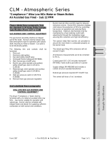
1. Nameplate Information
Each burner has a nameplate with job details, similar to
the nameplates shown in Figure A-1. The “X” in the JBEX
refers to a low NOx burner, where FGR is used to reduce
the NOx in the combustion gases. If the burner is not a
low NOx burner, there is no X in the model.
The serial number represents the unique number for that
burner and is a critical number that will be needed for any
communications with Webster Engineering.
The input rates dene the maximum and minimum inputs
for that burner, given in MBH for gas and GPH for oil. Air
atomized burners (Figure A-1) show both the oil pressure
and air pressure. Pressure atomized burners only list the
oil pressure. For gas ring, the gas manifold pressure is
given in “in wc” which is inches of water column.
The electrical ratings of the burner are given, with the
voltage, current load, frequency and phase (this will either
be single or 3-phase). For motors, the motor HP is listed.
2. Ratings
The ratings for each specic burner are given on the
nameplate (Figure A-1). The maximum and minimum
inputs are shown in Figure , based on the type of fuel.
Other conditions, like the supply gas pressure or the
combination of fuels, emission requirements and control
systems may limit the turndown.
The minimum furnace sizes are given in Figure A-4.
These are for combination, straight oil and 60 ppm NOx
(gas) burners. For gas only with no FGR, the lengths
can be 10% less. For 30 ppm NOx on gas, the minimum
dimensions must be 5% larger. The volume heat release
(VHR) is dened as the total input (BTU/hr) divided by
the furnace volume (ft
2
), and it should exceed the values
listed. Application testing and related burner adjustments
can be done to handle smaller furnace congurations.
Turndown is dened as the ratio of the maximum input to
the minimum input. For example, a burner with a maxi-
mum input of 120 GPH and a minimum input of 12 GPH
MODEL NUMBER
JBE5C-75K-U-RM7800L-M.25-MA-UL
SERIAL NUMBER
U123711A-01
JOB LOCATION
Des Moines, Iowa
DATE MFG
20 - Jul - 2019
OIL INPUT RATING
GAS INPUT RATING
MBTU/HR IN.WC
GPH PSI
16738
8.4
119.6 28/31
MAXIMUM
2790
0.15
23 12/21
MINIMUM
NATURAL GAS
#2 OIL / AIR
FUEL
VOLTS AMPS HERTZ PHASE
HP
115
CONTROL CIRCUIT
5
60 1
460
BURNER MOTOR
20.1
60 3
15
460
OIL PUMP MOTOR
2.9
60 3
1.5
Figure A-1 Nameplate

BURNER SERIES
JBE No FGR
JBEX With FGR
HOUSING SIZE
5, 7, 9
FUELS
G Gas
O Oil
C Gas / Oil
BLOWER MOTOR HP
50 5 HP
75 7.5 HP
100 10 HP
150 15 HP
200 20 HP
250 25 HP
300 30 HP
400 40 HP
500 50 HP
600 60 HP
750 75 HP
HEAD SIZE
J 12”
K 14”
L 16”
M 18”
N 20”
P 23”
MODEL JBE(X) BURNER MODEL CONFIGURATION
FIGURE A-2
JBEX5G - 75 K - RM7800L - M.25 - M - MA - UL/CSD-1
CODES AND
LISTINGS
UL
ULc
CSD-1
FM
IRI
NFPA-85
OIL SYSTEMS
Pressure Atomizing
MR Modulation By-Pass
Air or Steam Atomization
MA Air Atomization
MS Steam atomizing
GAS TRAIN VENDOR
VGD Siemens
VGG Siemens
M Maxon
Blank
All Others
(ASCO) - (std)
GAS TRAIN SIZE
.15 1 1/2 inches
.20 2 inches
.25 2 1/2 inches
.30 3 inches
.40 4 inches
GAS SYSTEMS
M Modulation
The above represents the common model designations.
Contact the factory for other options and special applications.
Page 5 Section A - GeneralJBE(X) Manual
FLAME SAFEGUARD VENDOR
DESIGNATION
RM7800L Honeywell
M Mark Autoame -mini mark
E110/EP170 Fireye
Nexus - N Fireye
LMV51 Siemens
LMV52 Siemens
LMV3 Siemens

has a 10:1 turndown. Burners equipped for high turn-
down (greater than 6:1) can have different equipment to
improve fuel, air and FGR ow control.
3. Product Offering
The JBE burner can re a variety of different vessels,
fuels and NOx levels. When red in any boiler except a
scotch marine retube boiler, a refractory shape is used
to contain the ame, and looks like a “tube”. The burner
can re natural gas, LP, digester and other types of gas,
as well as #2 through #6 fuel oil. See Figure A-4 for
minimum furnace sizes.
DO NOT USE GASOLINE, CRANKCASE OIL OR ANY
OIL CONTAINING GASOLINE.
This burner is also available as a low emission burner,
and will have model designation JBEX. Several low NOx
rates are available for all gas and light oil burners, with
the standard offering of 60 ppm, 30 ppm and 20 ppm
when ring natural gas. Low sulfur heavy oil can be
used with gas FGR, when the sulfur is under ½% (the
FGR is closed during oil ring).
4. Your Complete Manual
In addition to this manual, there are several other
documents that should be considered as part of the
complete manual for the burner. All of these documents
are needed to support the installation and startup of the
unit. These additional items include:
a. The wiring diagram, which shows the limits and
interconnection of the burner and vessel controls.
b. The gas and oil piping schematics, which show the
components and their relative positions in the piping
train.
c. The unit material list which provides an overview of
the burner requirements and a complete bill of
material, including the part numbers and description
for each item.
d. The ame safeguard manual provides the operating
sequence for the burner management system. This
will be a critical document for troubleshooting any
future problems.
e. Catalog cuts of the major components. These
provide details on the installation, adjustment and
maintenance of the components used on the burner.
Page 6 Section A - GeneralJBE(X) Manual
5. Service, Parts and Other Information
Service and parts are available from your local
Webster Representative. For a list of Webster
Representatives, please visit the Webster website at:
www.webster-engineering.com or call 620-221-7464.

Page 7 Section B- ComponentsJBE(X) Manual
No FGR 30 & 60 ppm NOx 20 ppm NOx
Max. Firing Rate
(GPH)
Figure A-3 - General Ratings
Nat. Gas or Propane
Model
Min. Firing Rate
(MBH)
Max. Firing Rate
(MBH)
Min. Firing Rate
(GPH)
Standard w/FGR Standard w/FGR Standard w/FGR Standard w/FGR
JBE(X)5*-50J 1,240 1,030 14,900 12,370 11 9 106 88
JBE(X)5*-75J 1,360 1,130 16,350 13,570 12 10 117 97
JBE(X)5*-75K 1,640 1,360 19,760 16,400 14 12 141 117
JBE(X)7*-100K 1,880 1,560 22,600 18,760 16 13 161 134
JBE(X)7*-150L 2,290 1,900 27,500 22,820 20 16 196 163
JBE(X)7*-200M 2,980 2,470 35,800 29,710 26 21 256 212
JBE(X)7*-250M 3,190 2,650 38,300 31,800 27 23 274 227
JBE(X)9*-300M 3,580 2,970 43,000 35,690 31 25 307 255
JBE(X)9-400M 4,750 3,940 57,000 47,310 41 34 407 338
JBE(X)9*-500N 5,000 4,150 60,000 49,800 43 36 429 356
JBE(X)9*-600P 5,670 4,700 68,000 56,440 49 40 486 403
JBE(X)9*-750P 6,170 5,240 74,000 62,900 53 44 529 439
Figure A-4 Furnace Conditions
Input
BHP
Input
MBH
Min. Furn.
Length
Min Furn.
Dia.
Max
Heat Rel.
Min Furn.
Dia.
Max
Heat Rel.
Min. Furn.
Dia.
Max Heat
Rel.
200 8369 116
26 185,000 26 175,000 28 165,000
250 10461 128
27 185,000 28 175,000 29 165,000
300 12553 138
29 185,000 30 175,000 31 165,000
350 14645 146
31 185,000 32 175,000 35 165,000
400 16738 154
33 185,000 35 175,000 36 165,000
450 18830 160
34 185,000 36 175,000 39 165,000
500 20922 166
35 185,000 37 175,000 42 165,000
600 25106 177
38 185,000 39 175,000 44 165,000
700 29288 185
39 185,000 41 175,000 46 165,000
800 33472 192
41 185,000 43 175,000 48 165,000
900 37656 200
42 185,000 44 175,000 50 165,000
1000 41840 205
43 185,000 46 175,000 52 165,000
1100 46024 210
44 185,000 47 175,000 53 165,000
1200 50208 215
45 185,000 48 175,000 54 165,000
1300 54392 220
46 185,000 49 175,000 56 165,000
#2 Fuel Oil
*Can be “G” (Gas), “O” (Oil) or “C” (Combination Gas/Oil)
(X) Optional FGR for low NOx operation
Note: Length & Diameter in inches. Heat release in BTU/cu.ft.

Page 8
Section B - Components
JBE(X) Manual
B. Components
1. General
2. Combustion Air
3. Burner Drawer
4. Gas Fuel Components
5. Oil Fuel Components
6. Flue Gas Recirculation (FGR)
7. Fuel-Air-Ratio Controls
8. Electrical Controls
Combustion
Air Motor
Wind Box
Burner
Mounting Flange
Atomizing Air
Pressure Switch
Figure B-1: General Burner Arrangement
Combination JBE(X) Burner – Front
Gas Control
Valve
Gas Spuds
Oil Nozzle
Access
Cover
Diffuser
Diffuser
Adjustment Bolt
Figure B-2: General Burner Arrangement
Combination JBE(X) Burner – Back
Flame Scanner
Drawer Assembly
Fuel Oil Low Pressure
Switch
Fuel Oil Shut Off
Valves
FGR Valve
Servos
Air Damper
Pilot Gas Regulator
Control Panel

Page 9 Section B - ComponentsJBE(X) Manual
Terminal Strip
Alarm Buzzer
Control Relays
Flame Safeguard
Motor Starter
Alarm Silencing
Switch (Optional)
On - Off Switch
Transformer
Power On Light
1. General
The JBE and JBEX burner lines are congured from a
common group of components that may vary in size and
style depending on the capacity, NOx level, fuels and
application. These common groups of components are
described in this section, however the exact detail of any
specic burner must be taken from the unit specic
information provided with each burner. This would
include the material list, wiring diagram, catalog cuts
and fuel train drawings.
2. Combustion Air Fan
A forward curved fan is used to supply the combustion
air to burn the fuel. If the burner is equipped with FGR
for low NOx, the fan will also provide the recirculated
ue gas. The fan diameter and width vary to match the
required combustion air ow, FGR rate, burner altitude
and vessel backpressure. The fan operates at 3550 rpm.
An inlet cone is used with the fan to provide a smooth
air ow transition to the fan. Each fan has a matching
inlet cone. The inlet cone should extend into the fan inlet
about 1/4 inch.
Fan and Motor Assembly
The combustion air fan and motor are assembled togeth-
er on a motor support plate that attaches to the windbox.
This assembly is built and balanced as a sub-assembly
that can be removed for maintenance and repair.
The fan has a hub that is machined to match the motor
shaft diameter and key. Setscrews are used to lock the
fan to the hub. The fan can be adjusted on the shaft to
provide the correct overlap between fan and inlet cone.
Several different motor styles can be used depending on
the application. An Open-Drip-Proof style is most com-
mon and used in a typical enclosed, clean environment.
A TEFC (Totally Enclosed Fan Cooled) would typically be
used in a dirty or wet environment. Other styles are also
available for special applications. The motor dimensions,
including the shaft diameter can vary by motor type.
Windbox
The windbox is an enclosure that routes the combustion
air from the fan to the ring head and provides the
primary mechanical structure for all of the components
of the burner. The combustion air fan and inlet cone are
contained within the windbox. The FGR adapter and air
damper are also connected to the windbox, opposite the
combustion air motor.
The windbox serves as the building block of the burner. It
requires good structural support to the boiler and oor to
handle the weight and movement of rotating components.
The multi-blade damper uses rubber seals on the blade
ends to improve sealing. On a single point positioning
Call for Heat Light
Gas On Light
Controller Reset
Power Failure
Manual Reset
Fuses
Alarm Light
Figure B-6
Control Panel (Gas Shown)

Section B - ComponentsJBE(X) Manual
Page 10
system (linkage), the damper shaft is connected by
linkage to the jackshaft. On a parallel positioning system
(linkageless), the shaft is directly coupled to the actuator
for the air damper.
The air damper mounts to the fan inlet and controls the
air ow to the fan. On low NOx burners, the air damper
is connected to the FGR adapter plate, so that the ue
gas can enter down-stream of the damper where there is
a negative pressure. If an optional silencer were used, it
would be mounted to the inlet of the air damper.
Blades
Figure B-7 Multi-blade damper
3. Burner Drawer
Figure B-8 Burner Drawer Assembly
The burner drawer contains the pilot, scanner, diffuser
and oil gun. These components are all attached to the
backplate. The burner drawer is removed as a complete
unit for adjustment and inspection. The burner drawer
slides through the windbox, head extension and into the
gas manifold. It is attached to the burner by bolting the
backplate to the windbox.
The pilot, scanner, oil gun and diffuser position can be
adjusted (in and out) by sliding the tube through the
backplate. Setscrews are used to lock these tubes into
position. The oil gun can be removed for inspection or
extended gas ring without removing the burner drawer.
Diffuser
The diffuser provides the directional control of the
combustion air for mixing and combustion stability. The
diffuser uses a combination of outer swirl air and inner
straight air. An inner ring is fastened to the diffuser in
some applications.
The JBE diffuser sits inside the head section of the
burner and is secured by one of two methods:
1) On smaller JBE(X)5 & JBE(X)7 burners with 12” and
Figure B-9 Diffuser
14” heads (“J” head and “K” head respectively), the
diffuser has two straps which attach the cylindrical
portion of the diffuser to the burner head extension.
Adjustment may be made by loosening the bolts in the
slotted holes located on each side of the head extension
and then carefully sliding them forward or back. Once
desired adjustment has been achieved, re-tighten bolts
to lock it in that position.
2) On larger JBE(X)7 and JBE(X)9 burners with 16” (“L”
head) and larger, the diffuser is attached to the center
tube of the drawer assembly. Adjustment to this type of
diffuser requires loosening the setscrews that secure the
center tube position on the back of the drawer assembly.
Once loosened, carefully slide the tube forward or back
through the drawer assembly backplate. When desired
position is achieved, re-tighten setscrews on back of
drawer assembly to secure the center tube. It may be
necessary to remove the diffuser (for example if spud
changes are to be made). First, ensure that all power
to the burner has been locked out. On smaller burners,
remove the two side fasteners used for adjustment of
diffuser, then remove the side access cover on the head
extension. Once the access cover is removed, it will be
necessary to partially withdraw the drawer assembly
in order to move the diffuser back. Once the diffuser is
moved back sufciently, it may be withdrawn sideways
through the access opening. Diffuser removal on larger
units is much the same, although there are no side bolts
through the head extension and the diffuser must be
unfastened from the center tube of the drawer assembly
before it can be withdrawn from the access opening.
When removing and re-installing the diffuser in the
JBE(X) burner, there are a few things to keep in mind.
First, the diffuser position is critical for proper ring.
Before removing or adjusting the diffuser, it is wise to
make reference marks where the diffuser position is set
(side bolts for smaller units or the large center tube on
larger units). Secondly, when re-installing a diffuser, it
is important that the scanner’s sight tube be positioned
properly. The diffuser will have a larger hole which the
scanner tube must pass through by at least 1/8”. Note
the hole position before removing the diffuser so that
when it is replaced, the hole will be in the correct position
and the sight tube may be placed through it. Also note
the position of the proven gas pilot with reference to the
sight tube. The tube is positioned next to the gas pilot so
that the swirl direction of the diffuser will cause the ame
of the pilot to curl in front of the scanner tube.

Section B - ComponentsJBE(X) Manual
Page 11
Scanner
The scanner is mounted to a sight tube that extends
past the face of the diffuser (approximately 1/8“)
where it can detect the pilot or main ame. This
location insures that it does not see the spark of the
pilot or reection off the refractory. The inside surface
of the scanner tube must be kept clean to prevent it
from absorbing the light and preventing the scanner
from detecting the ame.
Pilot
The pilot (Figure E-5) is positioned behind the
diffuser, so that the pilot ame passes through the
diffuser to ignite the main ame. It is located close to
the scanner tube, in the upstream direction to cause
the ame to pass in front of the scanner tube.
The pilot is connected to a gas pipe that extends
through the backplate in the burner drawer and can
be adjusted by moving the tube in the backplate. The
electrode is mounted to the venturi casting.
4. Gas Fuel Components
Gas Train
The gas train contains the safety shutoff
valves, manual shut-off valves, pressure
switches and other components that may be
required for the specic installation, available
Figure B-10 Typical Gas Train
gas pressure, insurance codes and local regulations.
The details of the gas train can vary greatly from
burner to burner. Gas trains are typically designed for
each application and a specic gas train assembly
drawing is provided for each unit, identifying the
major components. Details are provided in the
manual included with each burner.
The gas train shown in Figure B-10 uses a gas
pressure regulator upstream of two safety shutoff
valves. Another common style is to have the gas
pressure regulation built into the second safety
shutoff valve.
Gas Safety Shutoff Valve
Each gas train has two shutoff valves in the gas train.
These shutoff valves are usually motorized to open
and spring return to close. They may contain a proof
of closure switch to prove that the valve is in the
closed position prior to starting the burner.
High Gas Pressure Switch
This switch is located after the last shutoff valve
and before the gas ow control valve. It is set at a
pressure that is greater than the highest gas pressure
expected at this location. If the gas pressure rises
above this level, it will trip the switch and cause the burner
to shut down.
Low Gas Pressure Switch
This switch is located before the rst shutoff valve. It is set
to a pressure that is below the expected gas pressure at
this location. If the gas pressure falls below this setting, the
switch will trip and cause the burner to shut down.
Gas Pressure Regulator
Each gas train must have a gas pressure regulator. The
regulator insures a consistent supply pressure to the
burner. Often, the gas pressure regulator is the rst item
in the gas train, or it can be integrated into the second
shutoff valve.
Gas Control Valve
The gas control valve is used to modulate the ow of gas
fuel to the burner. On a single point positioning system
(linkage), it is connected to the jackshaft and uses a fuel
cam to make ne adjustments to fuel ow. When high
turndown is used with linkage, a gas valve with mechanical
stops and overtravel linkage is used to lock in low re. With
a parallel positioning system (linkageless), an actuator
is connected to the gas control valve, and modulated by
electronic control to the desired position. The gas control
valve is located on the pipe that connects to the manifold.
Gas Manifold
The gas manifold (gure B-11) is a cylindrical chamber that
has radial gas ports used to direct the gas fuel. Gas spuds
are installed in these radial ports to improve the distribution
of the gas. The gas manifold also holds the diffuser end of
the burner drawer, which ts tightly into the gas manifold.
This centers the diffuser in the gas manifold, which is
required to obtain good mixing of the gas and air.
The face of the gas manifold is protected from the high
ame temperatures by a refractory front plate, which is
designed to withstand high temperatures. In addition, a
ceramic blanket is used between the face of the manifold
and the refractory to slowdown the transfer of heat.
Rope Gasket
Ceramic Blanket
Figure B-11 Gas Manifold
Mounting Flange
The primary support for the burner is the mounting ange
on the gas manifold. This provides a clamping surface to

Section B - ComponentsJBE(X) Manual
Page 12
attach the burner to the vessel. A berglass rope gasket
(3/8” dia) is used to seal the mounting ange to the
refractory front plate. The rope is wrapped around the
ange several times to seal the full diameter of the ange.
In addition, a ceramic blanket is used in front of the gas
manifold to protect it from the internal temperatures of
the furnace. The ceramic blanket should be 1” thick by 2”
wide (Figure B-11).
Gas Spuds
A series of gas spuds are used to direct the gas into
the air stream. These gas spuds are located around the
circumference of the gas manifold. The gas spuds are
arranged in a manner that gives good mixing of the air
and fuel in conjunction with the diffuser.
Long Gas Spuds
Gas
Manifold
Short Gas Spuds
Figure B-12 Gas Spuds in Gas Manifold
Gas spud arrangement can change by fuel type, input
and NOx level. In some cases, eld adjustment of these
spuds is required to meet different furnace congurations
and eld conditions.
The gas spuds are stainless steel pipe nipples (1/8” NPT)
that are screwed into the gas manifold. Some of the holes
in the manifold are plugged with pipe plugs. “Never-
Seize” must be used on the pipe threads to prevent them
from seizing due to the heat at this location.
5. Oil Fuel Components
There are two different types of oil ring available; air
atomizing and pressure atomizing. The air atomizing
system requires an air compressor, or as an alternate,
plant air or steam.
The pressure atomizing system uses higher oil pressures
to atomize the oil. It will use return ow oil nozzles in a
tight cluster to provide atomization.
Oil Pump
The oil pump is used to supply oil to the nozzle at
sufcient ow and pressure. The oil pump is provided as
a separate item that must be mounted, wired and piped.
The assembly consists of the pump, motor, coupling,
pump-motor bracket and oil pressure regulator. The
motor base mount is used to secure the assembly.
Oil Pressure Regulator
An oil pressure regulator is used to maintain constant oil
pressure to the burner. It is adjusted to provide the oil
pressure needed at the nozzle. On small sizes, this may
be integral to the oil pump.
Oil Supply Pressure Gauge
This indicates the oil supply pressure from the pump.
Oil Train
The oil train contains the safety shut-off valves, pressure
switches and other components that may be required
for the specic installation, insurance codes and local
regulations and can vary from burner to burner. Oil trains
are designed for each application and a unit-specic oil
train drawing is provided with each unit. Details of the
components are provided with each burner.
Oil Safety Shutoff Valve
Each oil train has two shutoff valves. The valves can
be either solenoid or motorized type and can have an
optional POC (proof of closure) switch.
Low Oil Pressure Switch
This switch is set to a pressure below the expected oil
pressure and will trip if the oil pressure drops below this
level, shutting down the burner.
High Oil Pressure Switch
This optional switch is set to a pressure above the
expected oil pressure and will trip if the oil pressure rises
above this level, shutting down the burner.
Manual Ball Valve
A manual valve is provided in the oil line to perform
testing of the safety controls as part of the normal
startup procedures.
Oil Flow Control Valve
The oil ow control valve regulates the ow of oil to the
nozzle. In the air atomizing system, the control valve is
in the piping to the nozzle, directly regulating the ow of
oil. In the pressure atomizing system, the control valve is
located in the return line from the nozzle, controlling the
return ow, to indirectly control the oil ow to the nozzle.
The oil ow control valve modulates with the air damper
to provide different input rates. On a single point
positioning system (linkage), it is connected to the jack
shaft and uses a fuel cam to make ne adjustments to
fuel ow. With a parallel positioning system (linkageless),
an actuator is connected to the oil control valve and
modulated by electronic control to the desired position.
Figure B-13
Oil Pump and
Regulator

Section B - ComponentsJBE(X) Manual
Page 13
Oil Nozzle
Several different types of oil nozzles may be used
depending on the type of oil system, burner size,
turndown and application. They all share a common
purpose of atomizing the oil into small droplets so that
they will easily and quickly burn. All of the nozzles are
mounted to the end of the oil gun and inserted into the
support tube. The position of the nozzle can be adjusted
by moving the gun in the tube. The oil nozzles and
gun have a “Top and Bottom” position that is critical for
correct operation. The end of the oil gun is marked with
the word “TOP”.
Figures B-14 shows the components of typical air
atomizing nozzles. The nozzle tip and swirler are lapped
together to form a perfect t and can only be used
together as a matched set. Other air atomizing nozzles
may have slightly different construction.
Figure B-14 Typical Small Air Atomizing Oil Nozzle
Body
Swirler
Nozzle Tip
The pressure atomizing nozzle assembly (Figures B-15)
contains three smaller nozzles that are screwed into a
common body. These nozzles are not intended to be
cleaned internally. However, they can be cleaned on
the surface and the oil screen. The nozzles should be
replaced periodically when the combustion shows
signs of deterioration.
Nozzle Body
Pressure Atomizing
Nozzle
Figure B-15 Pressure Atomizing Oil Nozzles
Oil Gun
The oil gun (B-8) is an integral part of the burner drawer
assembly, but allows the oil nozzle to be adjusted in or
out for best combustion. It is made up of the oil nozzle,
oil supply pipe and either the air pipe (air atomizing) or
return line (pressure atomizing).
The gun assembly must be mounted in the correct
(vertical) position, with the word “TOP” located on top of
the assembly. This will allow for even oil distribution and
prevent oil dripping out of the gun and lines after shutoff.
Nozzle Oil Pressure Gauge
This gauge indicates the oil pressure at the oil nozzle.
This reading is important in determining proper operation
of the nozzle for atomization at any given ring rate.
There is a wide range of possible pressures, but typically
it is in the range of 5 to 40 psi for air atomizing and 65 to
160 psi for pressure atomizing.
Nozzle Atomizing Air Pressure Gauge
(For air atomizing burners only) This indicates the
atomizing air pressure at the nozzle. This reading is
important in determining proper operation of the nozzle
for atomizing the oil. The pressure can vary widely
depending on the nozzle and rate, but typically it will be
in the range of 5 to 40 psi.
Air Compressor
The air compressor, if used, provides air to the oil nozzle
to atomize the oil. The compressor assembly includes the
compressor motor, relief valve and exible connection to
isolate the vibration of the air compressor.
AirBleedValveandMufer
An air bleed valve is provided with air atomizing systems
to allow some of the air to bleed off and lower the
atomizing air pressure to optimize oil atomization. An air
mufer is provided to reduce the noise from this air ow.
In some cases, the bleed valve modulates with ring rate.
6. Flue Gas Recirculation (FGR)
The ue gas recirculation components in this section only
apply to the JBEX model that uses recirculated ue gas
to reduce the NOx emissions.
Air Filter
Motor
Flexible
Hose Air
Supply
Connection
Figure B-16 Large Air Compressor
Compressor
Motor
Base
Belt Guard
Figure B-17 Small Air Compressor
The ue gas recirculation components in this section only
apply to the JBEX model that uses recirculated ue gas
to reduce the NOx emissions.

Section B - ComponentsJBE(X) Manual
Page 14
FGR Adapter
The FGR adapter provides an interconnection between
the housing and air damper, placed in the air ow stream
to introduce the FGR. This location allows the FGR to
be “induced” into the air stream, because of the negative
pressure downstream of the air damper and created by
the burner blower wheel.
FGR Inlet Tube
This tube is inside the FGR adapter, and is positioned
to enhance the induction or negative pressure in the
FGR line. The tube can be adjusted to provide more or
less pressure by sliding it into or out of the air steam.
Setscrews are used to lock the tube into position. 60 ppm
systems do not use this tube.
Airow over this tube creates a negative pressure at
the FGR duct. The more this tube is moved into the air
steam, the more negative pressure is created.
FGR Control Valve
The FGR control valve controls the ow of recirculated
ue gas. The valve is connected to the FGR adapter and
inlet tube, which creates the pressure differential for ow.
This valve is normally smaller then the FGR duct line to
provide better ow control.
The FGR control valve modulates in conjunction with the
fuel/air valves to provide different input rates. On a single
point positioning system (linkage), it is connected to the
jackshaft. With a parallel positioning system (linkageless),
an actuator is connected to the FGR control valve and
modulated by electronic control to the desired position.
FGR Shutoff Valve
Single point positioning systems (linkage) require a
separate FGR shut-off valve that prevents ow during
the purge cycle. The valve is driven by a motor to close
the FGR line during the purge cycle. Parallel positioning
systems will modulate the control valve shut during purge
and do not require a shut-off valve.
The shutoff valve should be installed in the FGR duct
close to the boiler connection. The valve stem should be
horizontal, to prevent condensate from building in the
shaft bore, causing it to seize.
When ring oil, this valve may be closed or it may be
partially open to provide some FGR. If the valve is
intended to be partly open, there will be a potentiometer
in the control panel to adjust the position of this valve.
FGR Duct
The FGR duct provides the connection between the
boiler outlet and the control or shut-off valve. The design
of this duct is very important for proper operation and to
prevent maintenance problems (see Section C).
7. Fuel-Air-Ratio Controls
The burner may be equipped with single point positioning
(linkage), multiple setting modulating motor or parallel
positioning system (linkageless). All of these systems
provide the basic fuel-air-ratio control required for good
combustion, however they can provide different features
and setup capabilities.
Modulating Control
The burner modulates to match the energy requirements
of the load. It does this by using a sensor that measures
the pressure or temperature of the system and a
matching sensor in the modulating motor that moves to
match the readings of the sensor.
In some optional systems, a similar process is used with
an external control that provides a signal to the motor to
go to a certain rate. These systems may include multiple
burner sequencing, outside temperature compensation
and numerous other control strategies.
Single Point Positioning (Linkage)
Single point positioning systems use a single modulating
motor to vary the fuel input, air ow and other ow
changes like FGR and atomizing air ow. Linkage is
used to connect these ow control elements together
to provide a unied fuel-air-ratio control system. Other
elements in this system would typically include a
jackshaft, fuel cam and modulating motor.
Jackshaft
The jackshaft is a shaft that is used to tie the fuel, air
and FGR valves together with linkage, to provide a
uniform change in the ow as the burner modulates. A
modulating motor is used to drive the jackshaft, driven
by the requirement for heat in the system and as allowed
to operate by the ame safeguard.
The jackshaft is a round shaft that rotates and is
mounted in bearing supports. This provides a common
means of modulating all of the valves from a single
drive mechanism. The length can vary to meet overall
dimensions and individual drive arms are used to
connect to each valve.
Fuel Cam
A fuel cam is a mechanical linkage that allows for small
fuel rate changes without changing the linkage setting.
It can simplify the fuel-air-ratio adjustments during the
burner setup (Figure B-4).
Modulating Motor
The jackshaft is driven by a modulating motor that
rotates 90
o
to modulate the burner input from minimum
rate to maximum rate. Linkage is used to connect the
modulating motor to the jackshaft and the fuel cams
along with connecting the fuel, air and FGR control
valves to the jackshaft.
The standard modulating motor has two internal proving
switches. One switch, the Low Fire switch, proves the
low re position where the burner will light. This is also
the position the modulating motor will travel to when the
burner shuts down. The second switch, the High Fire
Purge switch, proves the high re purge position during
pre-purge.

Section B - ComponentsJBE(X) Manual
Page 15
Multiple Setting Modulating Motor
In some burner congurations, there are different ideal
settings for oil and gas ring, especially when higher
turndown is desired. This can be accommodated with an
optional modulating motor that has different low re and
high re positions for gas vs oil.
This optional modulating motor uses 4 to 8 internal
switches. One switch is used to prove the high re purge
position during pre-purge. A second is used to prove the
fully closed position. This is the position of the motor
when the burner is off. A third switch is used to prove the
Removable
Cover
Drive
Arm
Modulating
Motor
Figure B-18 Siemens Mod Motor Adjustments
ignition position – the point at which the burner will light.
A fourth switch is the low re position. This is the position
of lowest ring. It can be different from the ignition
position. If the burner is a combination gas-oil burner,
two additional switches may be used. These do the
same function as the third and fourth switches already
listed, but can be set up to allow for different ignition and
low re positions for gas and oil operation. There is also
a 7th and 8th switch that can be used to accommodate
two different high re settings. See the burner wiring
diagram to determine switch numbers and functions.
Oil Limiting Potentiometer
The fan is sized for air at rated capacity plus the quantity
of FGR required for gas NOx emissions. When ring oil,
the FGR rate is usually reduced, providing a larger fan
capacity than desired. To prevent the burner from over
ring on oil, a limiting potentiometer is used to limit the
oil rate. In this mode, the modulating motor is restricted
in its travel to something under 90
o
.
This potentiometer is located in the control panel and is
adjusted at startup to provide the correct oil ring rate.
Parallel Positioning System (Linkageless)
The Posi-Control system is a parallel positioning system
(linkageless) that uses individual actuators for each
control valve and a computer controller that directs each
actuator to provide the input change from minimum to
maximum capacity. The control provides more exibility
in setting each fuel rate (Figure B-2).
8. Electrical Controls
Control Panel
The control panel (Figure B-6) contains the ame
safeguard control, relays, terminal strips for electrical
connections and other components required for unit
control. Other components may be included for operation
of the boiler – a low water cutout relay, for example.
Flame Safeguard
The ame safeguard (Figure B-6) provides operational
control and safety sequencing for the burner. Safety
limits are tied to the unit and it controls the operation of
the fuel valves. The ame scanner is part of this and can
detect a ame failure, causing a shutdown. There are
several different ame safeguards available with different
features and costs. They can provide fault annunciation
and communications with other controls. The details of the
control used in the burner are supplied with the unit.
On-Off Switch
This switch is used to start and stop the burner by opening
or closing the limit circuit to the ame safeguard control.
Manual-Auto Switch and Potentiometer
The Man-Auto switch is used to select which signal source
is used for modulation control of the burner. With the switch
in the “Man” position, the burner ring rate is determined by
the position of the manual potentiometer. With the switch
in the “Auto” position, the burner ring rate is determined
by the signal from the boiler modulating controller. When
in the “Auto” position, the manual potentiometer can limit
the ring rate of the burner from anywhere between low re
and high re. The modulating motor will always drive open
and closed during pre-purge, regardless of the position of
the Man-Auto switch and potentiometer.
Fuel Transfer Switch
This switch selects the proper fuel for ring. It has a center
“off” position that prevents it from moving from one position
to the other, without stopping in the “off” position rst.
Power On light
Indicates that power is applied to the control panel.
Call For Heat light
Indicates the burner On-Off switch is closed and the boiler
limits are closed.
Fuel On light
Indicates the main fuel valve circuit has been energized.
Alarm light
Indicates the ame safeguard control is in a safety
shutdown and lockout condition. The ame safeguard
control reset button must be pressed before the burner can
operate again. On some burners, the Alarm light may also
be used to indicate other failure conditions such as low
water or high limit. See the wiring diagram for details on
what other controls may be wired to the Alarm light.

Section B - ComponentsJBE(X) Manual
Page 16
Junction Box
The junction box contains the electrical connections that
are required between the burner and control panel.
Manual Potentiometer Rate Control
The manual potentiometer is used to position the ring
rate when the burner “Auto-Manual” switch is in “Manual”
mode. It is used to setup and check the burner. When
in the “Automatic” position, this potentiometer acts as a
ring rate limiting potentiometer. Placing it at the low re
position will prevent the burner from modulating above
low re. For normal automatic operation, it must be
positioned at the full rate (clockwise) position.
Control Transformer (Optional)The control circuit
transformer is used to reduce the main power input to
115 VAC for the control circuit. If this electrical supply
could be provided as a separate input, this transformer
would not be required. The transformer has two fuses
located on the transformer box.
Alarm Bell
The alarm bell (or buzzer) provides an audible noise if
the burner were to lock out due to an alarm condition.
Control Relays
Relays are provided to support electrical options. The
number and type will vary with the equipment. Relays
will be indicated on both the wiring diagram and material
list.
Motor Starters
At least one motor starter, for the combustion air fan, will
be included in each control panel. If other motors are
used, for an oil pump or air compressor, these will also
be located in the control panel.

1. General Considerations
2. Refractory Frontplate
3. Burner Mounting
4. Gas Piping
5. General Oil Piping
6. Pressure Atomized Oil
7. Air Atomized #2 oil
8. Gas Pilot
9. FGR System
10. Draft and Stacks
11. Electrical
C. Installation
This section covers the installation procedures for the
JBE burner line. Your specic burner will not have each
of the systems discussed and may be supplied as an
installed system. If you receive the burner as part of a
new boiler for example, the burner will be installed in the
vessel with the piping already done. For this reason, a
review of the installation is required to determine which
tasks are complete and which need to be done.
THE INSTALLATION OF THE EQUIPMENT SHALL BE
IN ACCORDANCE WITH THE REGULATION OF
AUTHORITIES HAVING JURISDICTION, INCLUDING
THE NATIONAL ELECTRICAL CODE, INSURANCE
REGULATIONS AND ALL LOCAL CODES.
The equipment shall be installed in accordance with the
state and local requirements and in Canada, in accor-
dance with Provincial Installation Requirements, or in
their absence, the CGA B149.1 and B149.2 codes shall
prevail. Authorities having jurisdiction should be
consulted before installations are made.
NOTE TO INSTALLER: The main power disconnect
for this equipment must be conspicuously labeled and
placed within sight of the operating system and equipped
with lockout provisions.
1. General Considerations
In the initial planning of the installation, several items
must be covered:
a. Prior to starting the installation, collect and review all
technical literature to identify requirements. These
should include Installation & Operating Manuals for
the burner and vessel, the wiring diagram, fuel
schematics and technical literature on controls.
b. A general overview of the equipment should be
made prior to installation. Check the location of
access doors to insure they will function properly
when all equipment is installed. The burner and
control panel should have sufcient clearance for
the operator to monitor and perform maintenance. A
minimum clearance of 24” all around the burner
should be provided for maintenance. The burner
drawer and oil gun are pulled out from the front of
the burner so there must be sufcient space for this.
c. A source of combustion air must be provided for the
burner. Local codes often determine minimum
requirements, and these must be followed. In the
absence of other codes, the following can be used.
Webster recommends two air sources be provided,
one located high, one low. Each air source must
be at least 1 ft
2
. If there are multiple burners, the area
must consider all burner requirements. Exhaust fans
are not recommended as they create additional air
ow requirements to include in the area calculation.
The quantity of air required for combustion and
ventilation is 10 cfm/BHP. The maximum air velocity
is 250 ft/min from the oor to 7 feet high, and 500 ft
min above 7 feet high. Outdoor louvers may restrict
the open area, and if the exact restriction is unknown,
a restriction of 20% can be used. Add 3.5% to the
area for each 1000 ft above sea level. Calculations are,
Total air required (cfm) = BHP x 10
Open area = cfm / velocity
Louvered area = open area x 1.2 (or actual)
Area of opening = louvered area / 2
For example, with duct located under 6’ for a 500 HP
boiler, what would their area need to be? The total air
is (500 BHP x 10 cfm/BHP) = 5000 cfm. The maximum
velocity is 250 ft/min, so the open area must be =
(5000 cfm / 250 ft/min) = 20 ft
2
. Since these opening
will have louvers, the actual openings must be = (20 ft
2
x 1.2) = 24 ft
2
. There will be two opening, so each will
be = (24 ft
2
/ 2) = 12 ft
2
.
The location of the combustion air source must not
create a condition where the burner or vessel comes
in contact with very cold air (under 40
o
F) or causes
large uctuations in combustion air temperature. Cold
air can cause condensation below 40
o
F in a standard
burner and below 50
o
F when equipped with FGR.
There should be no large variations in combustion air
temperature supplied to the burner. The burner can be
adjusted to handle temperature variations of 30
o
F, but
may not be able to handle swings of 50
o
F without
combustion deterioration. In conditions where this can
occur, conditioning of the combustion air must be done
by location, bafing or pre-heating of the air. Seasonal
tune-ups also help cover large temperature swings.
d. There are several people that should be notied
before starting, including the owners representative,
the mechanical contractor, the electrical contractor,
the service organization and the boiler manufacturer.
e. DO NOT USE TEFLON TAPE or compounds with
Teon content as an oil or gas pipe sealant. Teon can
cause valves to fail creating a hazard. Warranties
are nullied and liability rests with the installer when
evidence of Teon is found.
f. Installer must clearly identify the main electrical power
disconnect and the manual shutoff valve on the gas
supply drop line to the burner.
Section C - Installation
JBE(X) Manual
Page 17

Section C - Installation
JBE(X) Manual
Page 18
Figure C-1 Refractory
Firetube Boilers

Section C - Installation
JBE(X) Manual
Page 19
Figure C-2 Refractory
Watertube Boilers

Section C - Installation
JBE(X) Manual
Page 20
The burner must be level.
Tighten clamp bolts
uniformly - check after
ring for several hours.
This surface must be
sealed against the vessel.
Check vessel mounting
requirements.
Refractory
Front Plate
Figure C-3
Burner Mounting Instruction
Check Valve
(See Note)
Strainer
Shutoff Valve
Return to Tank
Supply to Pump
Shutoff Valve
Vacuum
Gauge
Oil Pump
Burner
Oil Pressure
Regulator
Fuel Oil Tank
Note: Location of check valve
varies with system. Check valve
is usually located as close as
possible to tank outlet.
Figure C-4
Typical #2 Oil Field Piping
The gas piping from the burner to the train
should have as few elbows as possible to
reduce pressure drop.
Attachment to vessel varies with manufacturer
(follow vessel manufacturers recommendation.
Fiberglass rope gasket
must be coiled to
cover the full mounting
ange surface.
Fill voids
between front
plate and
vessel with
ceramic blanket
4” deep or as
dened by
vessel
manufacturer.
Entire O.D. of
refractory should
be covered.
/