Page is loading ...

HD COLOR CAMERA SYSTEM
SETUP
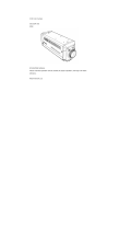
CONTROL UNIT
SU-1000
OPERATING INSTRUCTIONS
Please read this operating instruction carefully for proper operation,
and keep it for future reference.
Note: The model and serial numbers of your product are important for you to keep for your
convenience and protection. These numbers appear on the nameplate located on bottom of
the product. Please record these numbers in the spaces provided below, and retain this
manual for future reference.
Model No.
Serial No.

A
SAFETY INSTRUCTIONS
Carefully read all safety messages in this manual and safety Instructions on your equipment.
Follow recommended precautions and safe operating practices.
SAFETY ALERT SYMBOL
This is the “Safety Alert Symbol.” This symbol is used to call your attention to items or operations
that could be dangerous to you or other persons using this equipment. Read these messages and
follow these instructions carefully.
It is essential that you read the instructions and safety regulations before you attempt to assemble or use this
equipment.
The definitions of signal words are as follows:
WARNING: Personal danger
Warning notes indicate any condition or practice, which if not strictly observed, could result
in personal injury or possible death.
CAUTION: Possible damage to equipment
Caution notes indicate any condition or practice, which if not strictly observed or remedied,
could result in damage or destruction of the equipment.
NOTE: Notes indicate an area or subject of special merit, emphasizing either the product′s
capabilities or common errors in operation or maintenance.
WARNING: TO REDUCE THE RISK OF FIRE OR ELECTRIC SHOCK, DO NOT EXPOSE THIS COLOR
CAMERA TO RAIN OR MOISTURE.
AVERTISSEMENT
Afin d’éviter tout risque d’incendie ou d’électrocution, ne pas exposer l’appareil á la pluie ou á l’humidité.
Afin d’écarter tout risque d’électrocution, garder le coffret fermé.
Ne confier l’entretien de l’appareil qu á un personnel qualifié.
VORSICHT
Um Feuergefahr und die Gefahr eines eiektrischen Schiages zu vermeiden, darf das Gerät weder Regen noch
Feuchtigkeit ausgesetzt werden.
Um einen elektrischen Schiag zu vermeiden, darf das Gehäuse richt geöffnet werden.
Überiassen Sie Wartungsarbeiten stets nur einem Fachmann.
WARNING
CAUTION
NOTE
!
!
!
!

B
IMPORTANT SAFETY INSTRUCTIONS
1. Read Instructions
All the safety and operating instructions should be read before the product is operated.
2. Retain Instructions
The safety and operating instructions should be retained for future reference.
3. Heed Warnings
All warnings on the product and the operating instructions should be adhered to.
4. Follow Instructions
All operating and use instructions should be followed.
5. Cleaning
Unplug this product from the wall outlet before cleaning. Do not use liquid cleaners or aerosol cleaners.
Use a damp cloth for cleaning.
6. Attachments
Do not use attachments not recommended by the product manufacturer as they may cause hazards.
7. Water and Moisture
Do not use this product near water - for example, near a bath tub, wash bowl, kitchen sink, or laundry
tub; in a wet basement; or near a swimming pool; and the like.
8. Accessories
Do not place this product on an unstable cart, stand, tripod, bracket, or table. The product may fall,
causing serious injury to a child or adult, and serious damage to the product. Use only with a cart,
stand, tripod, bracket, or table recommended by the manufacturer, or sold with the product. Any
mounting of the product should follow the manufacturer's instructions, and should use a mounting
accessory recommended by the manufacturer.
9. Moving
A product and cart combination should be moved with care.
Quick stops, excessive force, and uneven surfaces may cause the product and cart combination to
overturn.
10. Ventilation
Slots and openings in the cabinet are provided for ventilation and to ensure reliable operation of the
product and to protect it from overheating, and these openings must not be blocked or covered.
The openings should never be blocked by placing the product on a bed, sofa, rug, or other similar surface.
This product should not be placed in a built-in installation such as a bookcase or rack unless proper
ventilation is provided or the manufacturer's instructions have been adhered to.
11. Power Sources
This product should be operated only from the type of power source indicated on the marking label. If
company. For products intended to operate from battery power, or other sources, refer to the operating
instructions.
12. Grounding or Polarization
This product is equipped with a three-wire grounding-type plug a plug having a third (grounding) pin.
This plug will only fit into a grounding-type power outlet. This is a safety feature. If you are unable to
insert the plug into the outlet, contact your electrician to replace your obsolete outlet. Do not defeat the
safety purpose of the grounding-type plug.
13. Power-Cord Protection
Power-supply cords should be routed to that they are not likely to be walked on or pinched by items
placed upon or against them, paying particular attention to cords at plug, convenience receptacles, and
the point where they exit from the product.

C
14. Lightning
For added protection for this product during a lightning storm, or when it is left unattended and unused
for long periods of time, unplug it from the wall outlet. This will prevent damage to the product due to
lightning and power-line surges.
15. Overloading
Do not overload wall outlets, extension cords or integral convenience receptacles as this can result in a
risk of fire or electric shock.
16. Object and Liquid Entry
Never push objects of any kind into this product through openings as they may touch dangerous voltage
points or short-out parts that could result in a fire or electric shock. Never spill liquid of any kind on
the product.
17. Inflammable and Explosive Substance
Avoid using this product where there are gases, and also where there are inflammable and explosive
substances in the immediate vicinity.
18. Heavy Shock or Vibration
When carrying this product around, do not subject the product to heavy shock or vibration.
19. Servicing
Do not attempt to service this product yourself as opening or removing covers may expose you to
dangerous voltage or other hazards. Refer all servicing to qualified service personnel.
20. Damage Requiring Service
Unplug this product from the wall outlet and refer servicing to qualified service personnel under the
following conditions:
a. When the power-supply cord or plug is damaged.
b. if liquid has been spilled, or objects have fallen into the product.
c. If the product has been exposed to rain or water.
d. If the product does not operate normally by following the operating instructions. Adjust only
those controls that are covered by the operating instructions as an improper adjustment of other controls
may result in damage and will often require extensive work by a qualified technician to restore the
product to its normal operation.
e. If the product has been dropped or damaged in any way.
f. When the product exhibits a distinct change in performance-this indicates a need for service.
21. Replacement Parts
When replacement parts are required, be sure the service technician has used replacement parts
specified by the manufacturer or have the same characteristics as the original part.
Unauthorized substitutions may result in fire, electric shock, or other hazards.
22. Safety Check
Upon completion of any service or repairs to this product, ask the service technician to perform safety
checks to determine that the product is in proper operating condition.
23. Wall or Ceiling Mounting
The product should be mounted to a wall or ceiling only as recommended by the manufacturer.
24. Heat
The product should be situated away from heat sources such as radiators, heat registers, stoves, or other
products (including amplifiers) that produce heat.

H
IMPORTANT NOTICE
For USA
These products have been tested and found to comply with the limits for a Class A digital device,
pursuant to Part 15 of the FCC Rules. These limits are designed to provide reasonable protection
against harmful interference when the equipment is operated in a commercial environment. This
equipment generates, uses, and can radiate radio frequency energy and, if not installed and used in
accordance with the instruction manual, may cause harmful interference to radio communications.
Operation of this product in a residential area is likely to cause harmful interference in which case the
user will be required to correct the interference at his own expense.
WARNING
Changes or modifications not expressly approved by Hitachi Kokusai Electric responsible for
compliance could void the user’s authority to operate the equipment.
For Canada
This product does not exceed the class A/class B limits for radio noise emissions from digital apparatus
as set out in the radio interference regulations.
Le présent appareil n’émet pas de bruits radioélectriques dépassant les limités applicable aux appareils
numériques de classe A prescrites dans le rVglement sur le brouillage radioélectrique édicter par le
ministére des communications du canada.

Contents
Outline and features .......................................................................................................................................... 1
Warnings and cautions when using .................................................................................................................. 2
Facility names and functions ............................................................................................................................. 3
LCD menu .............................................................................................................................................................8
Specifications .................................................................................................................................................. 22
Service information ............................................................................................................................................ 26

1
Outline and features
1.
1. 1.
1. General
GeneralGeneral
General
The setup control unit SU-1000 provides centralized control of SK-HD1000 series CCD high-definition
cameras offering abundant camera adjustment functions.
The compact and lightweight SU-1000 features Color LCD indicators in the display section and other
functions for easy use. The SU-1000 can be used for various purposes, including being mounted on a
broadcast OB Van
2.
2. 2.
2. Features
FeaturesFeatures
Features
(1) Abundant camera control functions
Up to 12 cameras can be controlled using the internal data line switcher (DSU).
Up to 48 cameras can be centrally controlled by connecting an external DSU(DU-1000) .
The main control items are:
- Auto setup execution
- Data file (PRESET、 SCENE FILE) selection, save, and clear
- Analog manual adjustment using the rotary encoder
- Maintenance on/off control
- PIX and WF video output select
(2) Compact and lightweight
The SU-1000 has been made compact, lightweight, and thin so it can easily be mounted on a broadcast relay
car.
(3) Improved operability
High-visibility Color LCD indicators are used on the display panel to provide a detailed display of the camera
status.

2
Warnings and cautions when using
CAUTION
Do not disassemble or modify
The camera contains precision internal
components. Do not open the cover or disturb
switches and controls other than designated.
There is risk of impaired performance and
damage.
Keep foreign object out of interior
Entry of water, metallic or other foreign
materials can cause failure and damage.
Select use and storage locations carefully
Avoid using or storing the equipment in the
following types of locations. Impaired
performance and damage can be caused.
Extremely hot or cold locations (exceeding -10
to 45°C), such as in enclosed vehicles.
Subject to strong vibration.
Humid or dusty locations.
Salt spray or corrosive gases.
Strong electromagnetic fields (e.g., near TV or
radio transmitters).
Where exposed to rain.
When connecting and disconnecting cables,
grasp the connector by the body, not the
attached cable. Cables can be damaged by
pulling on them.
Fuse replacement
Important: Although spare fuses are provided,
the fuse must be replaced only by a qualified
service technician.
In event of difficulty
Disconnect from power and contact the nearest
Hitachi Kokusai Electric service agency.

3
Facility names and functions (Front)
3.
3. 3.
3.
Facility names and functions
3.1 FRONT VIEW
POWER SWITCH
SU power switch.
Camera power switch
AUTO SETUP section
ON/OFF SWITCH section
LCD DISPLAY
MENU button and rotary encoder.
LCD display panel with touch panel.
PIX SEL/WFM SEL
SCENE FILES
SHUTTER / GAIN / ND/CC FILTER
CAMERA SELECT
MASTER BLACK / IRIS
A1
A2
A4
A6
A5
A6
A1
A2
A3
A4
A5
A7
A8
A7
A8
A3

4
Facility names and functions (Rear)
3.2 REAR VIEW
EXPAND data connecter
Connect external DSU to control more than
12 cameras
SWITCHER CTL connector (15 pin)
Use for parallel control switcher.
See Service information section.
RS-232C data connector (9 pin )
Use for serial control switcher.
See Service information section.
CCU connector (4 pin Hirose)
Connect to CCU .
See Service information section.
AC power input connector
Input of AC 90V to 230V.
LAN connector
Not used.
VE SW IN connector (15 pin)
Camera can be selected from Video Engeer
console via this connector.
See Service information section.
Wave Form Monitor (WFM) control
connector (15 pin )
This connector is used to select the display
mode of the waveform monitor.
See Service information section.
NO FUSE BREAKER(NFB)
FG terminal
Frame ground terminal.
B1
B2
B6
B3
B5
B7
B8
B9
B1
0
B1
2
B1
0
B1
B2
B5
B3
B4
B7
B8
B9
B10
B6
B4

5
Facility names and functions (Front)
POWER switch on/off
Set SCU Power switch to on.
AUTO SETUP SELECTION
S
Each type on/off control
A1
A2
A3
- PANEL ENABLE :
- BARS : Color BAR on/off
- TEST : TEST picture on/off
- CAP : Camera CAP MODE
- SD CARD : SD CARD slot
- CAM POWER : Camera power on/off
- CTL HEAD : Cameraman control enable
Auto setup selection switch: External chart, Auto white &
black and Break OFF for stop the auto set up process
- AUTOSETUP : Executes auto setup
- EXT CHART : Displays marker for auto setup
- SKIN TONE :
- AUTO WHITE : Executes auto white balance
- AUTO BLACK : Executes auto black balance
- BREAK OFF : Quits auto setup
- W CLIP OFF :White clip off
- KNEE OFF
- DETAIL OFF
- FLARE OFF
- GAMMA OFF
- AUTO KNEE ON
- HIGH CHROMA ON
- C.SAT ON : Chrome saturation on
- KNEE SAT ON : knee saturation on
- SD DTL OFF : Detail off for SD TV
- B.STR ON :Black stretch on
- MASKING ON : masking on for HD TV
- SKIN TONE MASK ON : skin tone masking on
- SKIN GATE ON
- MONO ON
- DTL KNEE OFF
- SKIN DTL ON

6
Facility names and functions (Front)
PIX / WFM select
Scene file select / Shutter,GAIN,ND,CC select
S
Camera select
Select the camera 1 to 12
STATUS off: not connected , yellow: camera power off , green: camera power on (normal state)
TALLY red: red tally , green: green tally , yellow: both red and green tally on
A5
A6
A7

7
Facility names and functions (Front)
Iris, Master black control, camera number display and call bottom.
LCD Display
Select display menu from left side item bottum.
Adjust menu item by using rotary encoder knobs.
A8
A4

8
LCD menu
4. MENU
structure
FUNCTION
ADJUST-1
ADJUST-2
FILE
CONFING
DATA
TOP SHUTTER MENU
GENERAL DETAIL MASKING
DETAIL LEVEL
SKIN DETAIL OTHERS
AUTO IRIS
SETUP LEVEL
CH1
CH2
THRESHOLD
CH/GATE SELECT
HIGH CHROMA
LINEAR 1
LINEAR 2
R Ye-R
G Cy-G
B Mg-B
SKIN TONE MASKING
CHROMA SAT
Ye G-Ye
Cy B-Cy
Mg R-Mg
LEVEL DEPEND
CRISP
BOOST FREQ
DETAIL KNEE
BALANCE
KNEE DETAIL
DETAIL SOURCE
BLACK
GAIN
FLARE
GAMMA
GAMMA TABLE
KNEE POINT
KNEE SLOPE
WHITE CLIP
KNEE SAT
WHITE SHADING
BLACK STRETCH
SYSTEM TIMING SD DETAIL ON/OFF
DETAIL LEVEL
LEVEL DEPEND
CRISP
BOOST FREQ
DETAIL KNEE
HD TIMING
SD TIMING
Y/C LEVEL
DATE/TIME BRIGHT BUZZER
BRIGHTDATE
TIME
SWITCHER
DATA TRANSFER SD CARD
SCENE FILE
BALANCE
OTHERS

9
LCD menu
5.1 LCD MENU
5.1.1 OPERATION menu (FUNCTION) & description.
5.1.2 SHUTTER menu (FUNCTION) & description.
5.1.3 MENU menu (FUNCTION) & description.
Item Setting
Factory
setting
Description
MENU
ON, OFF
---
UP,DOWN,
RIGHT,LEFT
ON, OFF ---
MULT ON, OFF ---
BARS ON, OFF OFF
Item Setting
Factory
setting
Description
SHUTTER
CC FRM⇔100/60⇔250⇔
500⇔1000⇔2000⇔
VARIABLE⇔AES
100
Selects shutter mode
VARIABLE 59.94
Adjusts shutter speed
---
SHUTTER ON, OFF OFF Shutter on/off button
Item Setting
Factory
setting
Description
ND
ND 1:CLEAR
ND 2:CROSS
ND 3:1/16ND
ND 4:1/64ND
CLEAR
Selects ND filters
CC
CC A:3200K
CC B:4300K
CC C:5600K
CC D:6300K
CC:E:8000K
3200K
Selects CC(ECC) filters
MASTER GAIN
-3dB,0dB,3dB~
+21dB,+24dB
0dB
Selects the Master gain
SHUTTER
CC FRM⇔100/60⇔250⇔
500⇔1000⇔2000⇔
VARIABLE⇔AES⇔OFF
OFF
Selects the shutter mode
and speed

10
LCD menu
5.2 ADJUST-1 MENU
5.2.1 GENERAL menu (ADJUST-1) & description.
ADJUST-1
DETAIL MASKINGGENERAL
0
R G
0
B
0
BLACK
GAINBLACK FLARE GAMMA
GAMMA
TABLE
KNEE
POINT
KNEE
SLOPE
WHITE
CLIP
KNEE
SAT
WHITE
SHADING
BLACK
STRETCH
CLEAR
+119
R G
-69
B
-18
GAIN
+2
R G
0
B
+4
FLARE
+1
R G
+11
B
+3
GAMMA
TOTAL
4.0
GAMMA TABLE
0
R TOTAL
0
B
0
KNEE POINT
+6
R TOTAL
0
B
0
KNEE SLOPE
TOTAL
+20
WHITE CLIP
TOTAL
0
KNEE SATURATION
0
R G
0
B
0
WHITE SHADING V-SAW
LEVEL
16
BLACK STRETCH
Item Setting Factory
setting
Description
BLACK
R
G
B
-128 to +127
-128 to +127
-128 to +127
Adjusts the black balance
manually
GAIN
R
G
B
-128 to +127
-128 to +127
-128 to +127
Adjusts the white balance
manually
FLARE
R
G
B
-128 to +127
-128 to +127
-128 to +127
Adjusts the flare correction
manually
GAMMA
R
G
B
-128 to +127
-128 to +127
-128 to +127
Adjusts the gamma balance
manually
GAMMA TABLE
TOTAL
3.0,3.5,4.0,4.5,5.0,5,
5,
Selects gamma table
KNEE POINT
R
TOTAL
B
-128 to +127
-128 to +127
-128 to +127
Adjusts the knee point
KNEE SLOPE
R
TOTAL
B
-128 to +127
-128 to +127
-128 to +127
Adjusts the knee slope
WHITE CLIP
TOTAL
-128 to +127
Adjusts the white clip level
KNEE SATURATION
TOTAL
-128 to +127
Adjusts the knee saturation
WHITE SHADING
V-SAW
R
G
B
-128 to +127
-128 to +127
-128 to +127
Adjusts the white shading
manually
BLACK STRETCH
LEVEL
-128 to +127
Adjusts the black stretch

11
5.2.2 DETAIL menu (ADJUST-1) & description.
ADJUST-1
GENERAL MASKINGDETAIL
DETAIL
LEVEL
LEVEL
DEPEND
CRISP
BOOST
FREQ
DETAIL
KNEE
BALANCE
KNEE
DETAIL
DETAIL
SOURCE
CLEAR
0
TOTAL H
0
V
0
DETAIL LEVEL
POINT
0
LEVEL DEPEND
0
H V
0
CRISP
FREQ
17MHz
BOOST FREQUENCY
0
WHITE BLACK
0
DETAIL KNEE
POSI/NEGA
8/8
BALANCE
LEVEL
0
WHITE DETAIL
SOURCE
R+G
DETAIL SOURCE
Item Setting Factory
setting
Description
DETAIL LEVEL
TOTAL
H
V
-128 to +127
-128 to +127
-128 to +127
Adjusts the detail level
LEVEL DEPEND
POINT
-128 to +127
Adjusts the level depend point
of detail
CRISP
H
V
-128 to +127
-128 to +127
Adjusts the crisp level of detail
BOOST
FREQUENCY
13MHz,14MHz,
17MHz
Adjusts the detail boost
frequency
DETAIL KNEE
WHITE
BLACK
-128 to +127
-128 to +127
Adjusts the detail knee point
BALANCE
POGI/NEGA
4:8,5:8,6:8
Selects the detail balance
KNEE DETAIL
LEVEL
-128 to +127
Adjusts the white detail level
DETAIL SOURCE
SOURCE
G, R+G, R+G+B
R+G
Selects the detail source
signal

12
5.2.3 MASKING menu (ADJUST-1) & description.
ADJUST-1
GENERAL DETAIL MASKING
CLEAR
LINEAR 1
0
R-G R-B
0
G-R
0
LINEAR 1
LINEAR 2
R
Ye-R
G
Cy-G
B
Mg-B
SKIN TONE
MASKING
CHROMA
SAT
Ye
G-Ye
Cy
B-Cy
Mg
R-Mg
0
G-B B-R
0
B-G
0
LINEAR 2
0
SAT HUE
0
SAT
0
HUE
0
R Ye-R
0
SAT HUE
0
SAT
0
HUE
0
G Cy-G
0
SAT HUE
0
SAT
0
HUE
0
B Mg-B
0
SAT HUE
0
SAT
0
HUE
0
Ye G-Ye
0
SAT HUE
0
SAT
0
HUE
0
Cy B-Cy
0
SAT HUE
0
SAT
0
HUE
0
Mg R-Mg
0
SAT HUE
0
SKIN TONE MASKING
TOTAL
0
CHROMA SATURATION
Item Setting Factory
setting
Description
LINEAR 1
R-G
R-B
G-R
-64 to +63
-64 to +63
-64 to +63
Adjusts the linear masking
LINEAR 2
G-B
B-R
B-G
-64 to +63
-64 to +63
-64 to +63
Adjusts the linear masking
R Ye-R
R SAT
R HUE
Ye-R SAT
Ye-R HUE
-64 to +63
-64 to +63
-64 to +63
-64 to +63
Adjusts the 12 vector masking
G Cy-G
G SAT
G HUE
Cy-G SAT
Cy-G HUE
-64 to +63
-64 to +63
-64 to +63
-64 to +63
Adjusts the 12 vector masking
B Mg-B
B SAT
B HUE
Mg-B SAT
Mg-B HUE
-64 to +63
-64 to +63
-64 to +63
-64 to +63
Adjusts the 12 vector masking
Ye G-Ye
Ye SAT
Ye HUE
G-Ye SAT
G-Ye HUE
-64 to +63
-64 to +63
-64 to +63
-64 to +63
Adjusts the 12 vector masking
Cy B-Cy
Cy SAT
Cy HUE
B-Cy SAT
B-Cy HUE
-64 to +63
-64 to +63
-64 to +63
-64 to +63
Adjusts the 12 vector masking
Mg R-Mg
Mg SAT
Mg HUE
R-Mg SAT
R-Mg HUE
-64 to +63
-64 to +63
-64 to +63
-64 to +63
Adjusts the 12 vector masking
SKIN TONE
MASKING
SAT
HUE
-64 to +63
-64 to +63
Adjusts the skin tone masking
CHROMA
SATURATION
TOTAL
-64 to +63
Adjusts the chroma saturation

13
5.2.4 SKIN DETAIL menu (ADJUST-1) & description.
ADJUST-1
GENERAL DETAIL MASKING
CLEAR
CH1 CH2 THRESHOLD
CH/GATE
SELECT
HIGH
CHROMA
Ye-R
LEVEL PHASE
0
PHASE FINE
0
WIDTH
0
CH1
Ye-R
LEVEL PHASE
0
PHASE FINE
0
WIDTH
0
CH2
LEVEL
0
THRESHOLD
CH1
CH GATE
CH1+2
CH/GATE SELECT
0
R G
0
B
0
HIGH CHROMA
5.2.5 OTHERS menu (ADJUST-1) & description.
12.00%
BLACK FLARE
5.00%
GAMMA
58.00%
SETUP LEVEL
ADJUST-1
GENERAL DETAIL MASKING
2/8
GATE PEAK/AVE
1
SPEED
0
AUTO IRIS
CLEAR
AUTO IRIS
SETUP
LEVEL
Item Setting
Factory
setting
Description
CH1
LEVEL
PHASE
PHASE FINE
WIDTH
-128 to +127
Ye-R,R-Mg,Mg-B,B-Cy,Cy-G,G-Ye
-128 to +127
-128 to +127
Adjusts the CH1 skin tone
detail parameter manually
CH2
LEVEL
PHASE
PHASE FINE
WIDTH
-128 to +127
Ye-R,R-Mg,Mg-B,B-Cy,Cy-G,G-Ye
-128 to +127
-128 to +127
Adjusts the CH2 skin tone
detail parameter manually
THRESHOLD
LEVEL
-128 to +127
Adjusts the threshold level
of the skin tone detail
CH/GATE SELECT
CH
GATE
OFF,CH1,CH2,CH1+2
CH1,CH2
Selects the Channel of the
skin tone detail and gate
HIGH CHROMA
R
G
B
-128 to +127
-128 to +127
-128 to +127
Adjusts the high chroma
detail
Item Setting
Factory
setting
Description
AUTO IRIS
GATE
PEAK/AVE
SPEED
1,2,3,4,5
0/8 1/8 …4/8
-128 to +127
Selects the auto iris gate
pattern and the
peak/average ratio
Adjusts the auto iris speed
SETUP LEVEL
BLACK
FLARE
GAMMA
0.0% … 12.35%
0.0% … 24.70%
42.20% … 67.70%
5.0%
12.0%
58.0%
Adjusts
the black setup level
the flare reference level
the gamma cross point

14
5.3 ADJUST-2 MENU
5.3.1 SYSTEM TIMING menu (ADJUST-2) & description.
ADJUST-2
SD DETAIL
SYSTEM
TIMING
CLEAR
HD
TIMING
SD
TIMING
Y/C
LEVEL
H PHASE
0
HD TIMING
0
SDI H PHASE VBS H PHASE
0
SC COARSE
0°
SC FINE
0
SD TIMING
0
Y C
0
Y/C LEVEL
ON/OFF
5.3.2 SD DETAIL menu (ADJUST-2) & description.
ADJUST-2
SYSTEM
TIMING
SD DETAIL
CLEAR
DETAIL
LEVEL
LEVEL
DEPEND
CRISP
BOOST
FREQ
DETAIL
KNEE
0
TOTAL H
0
V
0
DETAIL LEVEL
0
POINT SLOPE
0
LEVEL DEPEND
0
H V
0
CRISP
FREQ
6MHz
BOOST FREQUENCY
POSI/NEGA
8/8
BALANCE
BALANCE
0
WHITE BLACK
0
DETAIL KNEE
ON/OFF
Item Setting Factory
setting
Description
HD TIMING
H PHASE
-128 to +127
---
Adjusts the HD timing for
external sync
SD TIMING
SDI H PHASE
VBS H PHASE
SC COARSE
SC FINE
-128 to +127
-128 to +127
0° 90° 180° 270°
-128 to +127
---
Adjusts the timing for Genlock
Y/C LEVEL
Y
C
-128 to +127
-128 to +127
--- Adjusts Y and C signal level
Item Setting Factory
setting
Description
DETAIL LEVEL
TOTAL
H
V
-128 to +127
-128 to +127
-128 to +127
Adjusts detail level
Total : Horizontal and Vertical
H : Horizontal
V : Vertical
LEVEL DEPEND
POINT
SLOPE
-128 to +127
-128 to +127
Adjusts level depend
POINT : Threshold point
SLOPE :
CRISP
H
V
-128 to +127
-128 to +127
Adjusts crisp threshold
H : Horizontal
V : Vertical
BOOST
FREQUENCY
Selects Boost frequency
DETAIL KNEE
WHITE
BLACK
-128 to +127
-128 to +127
Adjusts detail knee point
BALANCE
POGI/NEGA
Adjusts detail balance
/