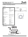
Danfoss FH-BU and FH-RT Installation guide
- Type
- Installation guide
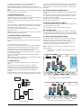
Danfoss FH-BU and FH-RT provide wireless control of underfloor heating systems, offering individual room temperature control for enhanced comfort and energy efficiency. With up to 8 thermostats, you can set and adjust temperatures in different rooms, ensuring a comfortable environment in each space. The system operates on radio frequency, allowing for easy installation without the hassle of running wires. Additionally, the FH-RT thermostats are battery-powered, eliminating the need for electrical connections, providing greater flexibility in placement.
Danfoss FH-BU and FH-RT provide wireless control of underfloor heating systems, offering individual room temperature control for enhanced comfort and energy efficiency. With up to 8 thermostats, you can set and adjust temperatures in different rooms, ensuring a comfortable environment in each space. The system operates on radio frequency, allowing for easy installation without the hassle of running wires. Additionally, the FH-RT thermostats are battery-powered, eliminating the need for electrical connections, providing greater flexibility in placement.


-
 1
1
-
 2
2
-
 3
3
-
 4
4
-
 5
5
-
 6
6


Danfoss FH-BU and FH-RT Installation guide
- Type
- Installation guide
Danfoss FH-BU and FH-RT provide wireless control of underfloor heating systems, offering individual room temperature control for enhanced comfort and energy efficiency. With up to 8 thermostats, you can set and adjust temperatures in different rooms, ensuring a comfortable environment in each space. The system operates on radio frequency, allowing for easy installation without the hassle of running wires. Additionally, the FH-RT thermostats are battery-powered, eliminating the need for electrical connections, providing greater flexibility in placement.
Ask a question and I''ll find the answer in the document
Finding information in a document is now easier with AI
Related papers
-
Danfoss CET B-RF Installation guide
-
-
-
-
-
-
-
-
-
Other documents
-
OJ Electronics WLM Operating instructions
-
Uponor Smatrix Wave Owner's manual
-
-
-
-
-
-
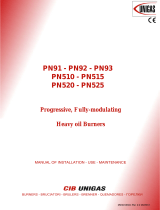 Unigas PN520 Manual Of Installation - Use - Maintenance
-
Fujitsu WSYG160DJ6/WOYG160LJL Installation guide
-
Fujitsu WGYK170DJ9/WOYK170LJL Installation guide
