Page is loading ...

USER
MANUAL
360mm
14,17in
282mm
11,11in
266mm
10,46in
90mm
3,54in
157mm
6,18in
219mm
8,62in
277mm
10,92in
188mm
7,38in
255mm
10,02in
24mm
0,95in
201mm
7,91in
107mm
4,21in
220°
465mm
18,30in
371mm
14,59in
MOVING HEAD SERIES
G-4 WASH (POI)
G-4 W WASH
G-4 WASH-BEAM (POI)
G-4 W WASH-BEAM
G-4 WASH MOTORIZED BARNDOORS

2
G-4 SERIES
USER MANUAL REV. B
© 2018 SGM
TM
. In this manual is information subject to change without notice. SGM and all afliated companies
disclaim liability for any injury, damage, direct or indirect loss, consequential or economic loss, or any other loss
occasioned by the use of, inability to use, or reliance on the information contained in this manual.
The SGM logo, the SGM name, and all other trademarks in this document pertaining to services or products by
SGM or its afliates and subsidiaries are trademarks owned or licensed by SGM, or its afliates or subsidiaries.
This edition applies to rmware version 3.18 or later.
English edition
This manual covers installation, use, and maintenance of the G-4 Series.
A digital version is available at www.sgmlight.com, or upon request via [email protected].

3
Contents
Safety information .....................................................................................................................5
Overview .................................................................................................................................6
Preparing for installation ............................................................................................................7
Installing / rigging the G-4 ..........................................................................................................8
Connecting AC power ................................................................................................................9
Conguring the device .............................................................................................................10
Display settings ....................................................................................................................10
Connecting to a DMX control device ..........................................................................................11
Conguring the device for DMX control ......................................................................................11
Full Color Calibration and Color Temperature Correction .............................................................13
Internal programs ...................................................................................................................13
Pan / Tilt positions ..................................................................................................................13
Fixture properties ...................................................................................................................14
Control menu .........................................................................................................................15
RDM ......................................................................................................................................16
Troubleshooting .....................................................................................................................16
Accessories ...........................................................................................................................17
Ceiling mount bracket ..............................................................................................................17
G-4 Wash Top Hat ...................................................................................................................19
Interchangeable front lens ........................................................................................................20
Motorized Barndoors ...............................................................................................................20
SGM Uploader cable ................................................................................................................21
SGM Vacuum Test Kit ..............................................................................................................22
POI Permanent Outdoor Installation...........................................................................................23
Maintenance ...........................................................................................................................25
Fixtures and accessories .........................................................................................................26
Support hotline .......................................................................................................................26
Approvals and certications .....................................................................................................26
User Notes .............................................................................................................................27

4
G-4 Series dimensions
G-4 Wash / G-4 W Wash
G-4 Wash / G-4 W Wash with Top Hat
All dimensions in milimeters and inches. Drawing not to scale.
G-4 Wash Motorized Barndoors
G-4 Wash-Beam / G-4 W Wash-Beam

5
Safety information
• Do not open the device; there are no user-serviceable parts inside.
• Ensure that power is cut off when wiring the device to the AC mains supply.
• Ensure that the device is electrically connected to earth (ground).
• Do not apply power if the device or mains cable is in any way damaged.
• Do not immerse the xture in water or liquid.
DANGER! Risk of electric shock. Do not open the device.
• Install in a location that prevents accidental contact with the device.
• Install only in a well-ventilated space.
• Install at least 0.3 m (12 in.) away from objects to be illuminated.
• Install only in accordance with applicable building codes.
• Ensure a minimum clearance of 0.3m (12 in.) around the cooling fans.
• Do not paint, cover, or modify the device, and do not lter or mask the light.
• Keep all ammable materials well away from the device.
• Allow the device to cool for 15 minutes after operation before touching it.
CAUTION: Exterior surface temperature after 5 min. operation = 45 °C (113 °F). Steady state = 68 °C (154 °F).
WARNING! Take measures to prevent burns and re.
• Do not look directly at the light source from close range.
• Take precautions to prevent injury due to falls when working at height.
• For Permanent Outdoor Installations (POI), ensure that the xture is securely fastened to a load-bearing surface with suitable
corrosion-resistant hardware.
• For temporary installations with clamps, ensure that the quarter-turn fasteners are turned fully and secured with a suitable
safety cable.
• For elevated installations, secure the xture with suitable safety cables and always comply with relevant load dimensioning,
safety standards and requirements.
• The standard safety wire cable must be approved for a safe working load (SWL) of 10 times the weight of the xture, and
it must have a minimum gauge of 4 mm.
WARNING! Take measures to prevent personal injury.
WARNING!
Read the safety precautions in this section before installing, powering, or operating
this product.
SGM luminaries are intended for professional use only. They are not suitable for household use.
Les luminaires SGM sont impropre à l’usage domestique. Uniquement à usage professionnel.
Review the following safety precautions carefully before installing or operating the device.

6
The G-4 Series
• A high power LED moving head luminaire weighing only around 10 kg/22 lbs
• IP-65-rated (standard) and IP-66-rated (POI) enable operation in temperatures from -40˚C to 50˚C in all kinds of weather
• Working within the 100-240V 50/60 Hz range (standard base)
• Providing built-in wireless DMX and presetable stand-alone programs
• Capable of continuous clockwise and counter-clockwise pan rotation, controlled in four different pan modes
• Fully RDM implemented
• Interchangeable lens kit and optional top hat accessory to minimise stray light
The lightsource of the xture is expected to run for about 50,000 hours LM-70/TM-21.
The variants
• The G-4 RGBAM - ve color 150W LED - red, green, blue, amber and mint (CRI >90)
• The G-4 W - extremely bright white with 7,200K 150W LED’s, or 5,000K with CTO lter inserted
G-4 RGBAM also features
• Color lter macro used to mimic congo blue and deep saturated red
• Color lter emulating 89 LEE colors + raw amber and raw mint
• Fully adjustable CTC from 2,000K to 10,000K
• Plus / Minus green control
Lens options
Overview
D
E
F
K
A
H
B
G
I
J
L
A: Interchangeable front lens
B: Power in
C: G-4 Wash front lens
D: Display panel
E: Yoke handles
F: Tophat (accessory)
G: G-4 Wash-beam front lens
H: G-4 Motorized barndoors front lens
I: Camlocks for omega bracket
J: DMX in and out
K: Safety wire attachment points
L: Ceiling mount bracket (accessory)
C
Parts identication and terminology
Figure 1: G-4 Series parts and terminology
G-4 RGBAM G-4 White
Wash 9 - 76° Zoom 9 - 80° Zoom standard lens kit
Wash w/top hat - -
accessory for Wash lens kit to
minimize stray light
Wash-Beam 4.8 - 34° Zoom 4.4 - 34° Zoom
available as complete xture or
accessory lens kit
Motorized
barndoors
9 - 76° Zoom N.A.
available as complete xture or
as lens kit (accessory)

7
Unpacking
Unpack the device and inspect it to ensure that it has not been damaged during transport.
The G-4 Series is shipped with:
• One Neutrik TRUE1 power input connector, 2 m (78 in.)
• One Omega bracket with 1/4-turn fasteners
• Removable diffusion lter (for G-4 Series Motorized Barndoors only)
Location / application
The G-4 Series is IP65-rated and designed for use in outdoor events. This means that it is protected from:
• Dust, to the degree that dust cannot enter the device in sufcient quantities so as to interfere with its operation
• Lower pressure jets of water from any direction
In the G-4 Wash Motorized Barndoors, while the xture is full IP65-rated, the motorized barndoors module is IP20-rated. Therefore,
the motorized barndoors are not protected from water and dust.
When selecting a location for the device, ensure that:
• It is situated away from public thoroughfares and protected from contact with people
• It is not immersed in water or exposed to high-pressure water jets
• It has adequate ventilation
When using the xture for outdoor events, ensure that:
• For wireless DMX or standalone operation, the DMX-out cable is securely attached to the DMX-in connection.
(See “Parts identication and terminology” on page 6.)
• For cabled DMX operation, the DMX out of the last xture is terminated with a 120 Ohm resistor between pin 2 and 3
(according to the RS485 standard), and the DMX out is properly sealed, in accordance with the IP65 requirements.
A maximum of 32 xtures can be connected to the same DMX link.
Transportation
Always use the supplied packaging or suitable ight case for transportation and storage the device.
Never carry your G-4 Series by connected cables, wires, or motorized barndoors (when installed). Doing so may cause severe
damage to the xture. Always use the handles to carry the xture.
Locating the front of the xture
The front of the G-4 Series is the opposite side of the AC power socket.
The front it is marked with an arrow, as shown in the illustration below.
Preparing for installation
FRONT
Figure 2: Front of the G-4 Series

8
C
B
E
D
A: Omega Bracket
B: 1/4-turn locking points - Base
C: Safety wire points - Base
D: 1/4-turn locking points - Ceiling mount
E: Safety wire points - Ceiling mount
A
The G-4 Series may be installed in any orientation, with base or with ceiling mount.
Always use an omega bracket to rig the xture and lock the bracket with the 1/4-turn fasteners.
Please note: The 1/4-turn fasteners are only locked when turned fully clockwise.
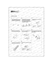
Rigging process
Start the rigging process by blocking the working area below the xture. Make sure the work is performed from a stable platform.
1. Check that the clamp is undamaged and can bear at least 10 times the weight of the xture. Check that the structure can
bear at least 10 times the weight of all installed xtures, lamps, cables, etc.
2. Bolt the clamp securely to the omega bracket with an M12/ ½ bolt (min. grade 8.8) and a lock nut.
3. Align the omega bracket with the two 1/4 turns in the base. Insert the fasteners into the base and turn both levers a full1/4-
turn clock wise to lock.
4. Working from a stable platform, hang the xture on a truss or other structure. Tighten the clamp.
5. Install a safety wire that can bear at least 10 times the weight of the xture. The safety wire attachment point is designed to
t a carabine.
6. Verify that there are no combustible materials, cables, or surfaces to be illuminated within a distance of 0.3 m (12 in.) from
the xture.
7. Check that there are no possibility of head or yoke colliding with other xtures or structures.
Ceiling mount bracket (accessory sold separately)
The G-4 Series may also be installed using a ceiling mount bracket. When using the ceiling mount, there are no base with power
supply, therefore, the xture must be powered by an external PSU.
See on pages 17-18 how to install the ceiling mount bracket.
Installing / rigging the G-4
WARNING! Always secure an elevated G-4 Series with a safety wire
Fasten a safety wire (not shown) between the load-bearing support structure and the safety wire attachment point on the device.
The safety cable (not included in the package) must be able to:
• Bear at least 10 times the weight of the device (SWL)
• Have a minimum gauge of 4 mm
• Have a maximum length (free fall) = 30 cm (12 in.)
CAUTION!!
• Always use a safety wire
• Make sure the slack of the safety wire is at a minimum
• Never use the carrying handles for secondary attachment
Safety wire attachment point
Figure 4: Ceiling mount bracket
A: ISO View
B: Front view
C: Back view
D: Right side view
E: Top view
A
E
B
D
Measurements in millimeters
C
Figure 5: Safety wire attachment point
Figure 3: Installing the G-4 Series

9
Connecting AC power
The G-4 Series standard version can operate on any 100–240V, 50/60 Hz AC mains power supply.
The G-4 Series maximum power consumption is 250W.
For temporary outdoor installations, connect the G-4 Series to AC power using the supplied cable with Neutrik powerCON TRUE1
NAC3FX-W (or similar), to ensure the correct ingress protection (IP-rating).
The mains cable must be tted with a grounded connector intended for exterior use.The device must be grounded/earthed and able
to be isolated from AC power. The AC power supply must incorporate a fuse or circuit breaker for fault protection.
CAUTION!!
Do not open the xture to replace the supplied power cable.
Do not connect the xture to an electrical dimmer system, as doing so may cause damage.
When installing standard type C circuit breakers, there will be no limitations due to the xture in-rush current.
For assistance with alternative congurations, contact your SGM representative.
After connecting the G-4 to power, run the on-board test, going to “MENU → TEST →AUTOMATED TEST”, to ensure the xture and
each LED are functioning correctly. Please see “Control menu” on page 15.
For permanent outdoor installations, the G-4 POI versions supplies a power cable with bare ends. Please refer to page 22 for
connecting AC power in POI xtures. For POI, have a qualied electrician to wire the mains cable directly to a suitable branch circuit.
The junction’s ingress protection (IP-rating) must be suitable for the location.
PLEASE NOTE:
Both DMX-in and DMX-out must be connected in order to maintain the IP65-rating.
The G-4 Series without base and/or with ceiling mount bracket operates on 36V DC power and external power supply.
See in detail on page 18-19 how to install the ceiling mount bracket.
The fixture must be grounded/
earthed and be able to be isolated
from AC power. The AC power
supply must incorporate a fuse or
curcuit breaker for fault protection.
Color
Black
White
green/yellow
Conductor
live
neutral
ground (earth)
Symbol
or
L
N
Wire
Figure 6: Connecting AC Power

10
Conguring the device
Set up the xture using the control panel and OLED display at the yoke of the xture.
After powering on the G-4 Series, the display shows the currently selected operating mode. Navigate through the menus using the
arrows and select items using the ENTER button.
Please note: In POI versions there is no display mounted in the xture. The adjustments are made through RDM.
See page 22 to know more.
OLED Display (A)
The OLED multiline display is the human interface of the xture. It displays the
current status and menu of the xture. The display panel can be used to congure
individual xture settings, checking the xture’s wireless status, rmware version,
and error messages. The complete list of the menu and all commands available
are listed in ”Control menu” on page 15.
Using the keyboard (B)
• Press the ‘ENTER’ button to enter a menu or make a selection.
• Press the arrows to scroll up and down the menus.
• Press the ‘ESC’ button to take a step back.
• Press any button to disable pan/tilt - it generates time out for 10 sec.,
after which it will return to the correct position.
Wireless signal strength (C)
Displays the signal strength of the wireless CRMX connection. The wireless signal
strength symbol will be ashing if the paired transmitter is out of range.
If no transmitter is paired the symbol will be off.
Active input type (D)
The active input is displayed for quick and simple verication of the input status.
Error indicator (E)
If any errors are detected, the message ‘ERR’ will be ashing in the display for easy detection.
To read the error message go to: MENU → INFO → ERRORS
DMX address (F)
Displays the current DMX address. The DMX address can be changed directly from this view. The next available DMX address is
displayed to the right. The DMX address will ash on the display if no data input.
Next xture address (G)
Showing the next available DMX address depending on the xture’s DMX footprint.
113
DMX (131)
INFO
SETTINGS
TEST
RESET
113
DMX (131)
113
INTE (131)
ERR
CRMX (131)
A: OLED Display E: Error indicator
B: Keyboard F: DMX address
C: Wireless signal strenght G: Next fixture address
D: Acve input type
B
D
A
F
G
E
C
Figure 7: Control panel
Flipping the OLED display
If the xture is hanging upside down, it might be useful to ip the display for easy reading.
To ip the display select “ENTER → SETTINGS → DISPLAY FLIP” in the menu, or press the ‘UP’ and ‘DOWN’ arrows simultaneously
in the control panel.
Setting the OLED display saver
By default, the OLED display dims down after a short period of time whenever the control panel is not in use, but it can also be set to
turn off completely. Pressing any key will turns on the display or restore it to normal brightness.
To change the display saver, select “ENTER → SETTINGS → DISPLAY OFF” in the menu. This can also be changed via RDM.
See “RDM functions” on page 16.
NOTE: To avoid the risk of display deterioration caused by long term use in permanent installations, it is recommended to
use the “DISPLAY OFF” setting.
Display settings

11
The G-4 Series is controllable using a DMX control device, and it can be connected using either a DMX cable or via the xture’s
build-in LumenRadio CRMX wireless receiver system.
If using a cabled DMX system, connect the DMX-in cable to the input connector under the base of the xture (chassis mounted
male 5-pin XLR connector) and DMX-out to the output cable also under the base (female 5-pin XLR plug). Terminate the DMX-out
cable of the last xture in the data link.
For outdoor events, use only IP65-rated XLR connectors. If using a wireless DMX system, ensure that the DMX output is connected to
the DMX in connector and properly inserted. Connect both DMX in and DMX out cables in order to maintain the xture’s IP65-rating.
Note: for POI versions, please refer to page 22 to see how to connect DMX and AC power.
Connecting a wireless transmitter
The G-4 Series is designed to look for wireless transmitters in ‘connect’ state, when this option is not yet enabled.
To connect the G-4 Series to a wireless transmitter:
• Log off the currently paired wireless transmitter. See “Disconnecting a wireless transmitter” on page 9.
• Press the connect button on the wireless transmitter.
• Conrm that the xture has paired with the wireless transmitter.
Note: for POI Versions, please refer to page 23 to see how to connect the wireless transmitter.
Disconnecting a wireless transmitter
To disconnect the xture from the currently paired wireless transmitter, go to:
MENU → SETTINGS → WIRELESS DMX → LOG OFF.
Note: for POI versions, refer to page 23 to see how to disconnect the wireless transmitter.
Signal priority
The G-4 Series can be paired to an active wireless transmitter simultaneously as being connected to a cabled DMX. The device will
prioritize cabled DMX over the wireless DMX.
The active input type is displayed under the wireless signal strength indicator. The signal strength can be also checked via RDM data
by using a external RDM device (e.g. the SGM A-4).
Note: In POI versions with wireless, the DMX signal strength can only be checked through RDM.
About DMX
The G-4 Series can be controlled using signals sent by a DMX controller on a number of DMX channels. DMX is the USITT
DMX512-A standard, based on the RS-485 standard. The signal is sent as DMX data from a console (or a controller) to the xtures
via a shielded, twisted pair cable designed for RS-485 devices.
The cables can be daisy chained, and up to 32 xtures can be connected to the same DMX link. Up to 300 meters (1000ft.) of cable
is achievable with high quality DMX cables. All DMX links must be terminated in the last xture by connecting a DMX termination plug
to the last xture´s 5 pin DMX out connector.
PLEASE NOTE:
Standard microphone cable is not suitable for transmitting DMX.
Up to 32 xtures can be on the same DMX link. Additional xtures will overload the link.
The last xture must always be tted with a DMX termination plug to the xtures DMX out.
Set/edit DMX address
The DMX address is shown at the OLED display in the control panel.
To change the address setting, press the up and down arrows. When the desired address is
displayed, press ‘ENTER’ to save the setting.
For your convenience, the next available DMX address is displayed to the right.
The G-4 Series also offers the option to set the DMX address through RDM.
NOTE: POI versions are only addressable via RDM.
Connecting to a DMX control device
Conguring the device for DMX control
113
DMX (131)
Figure 8: Set the DMX address

12
DMX modes
The G-4 Series operates in different modes.
All DMX charts are available at www.sgmlight.com under the respective products, or upon request via [email protected].
DMX Start address
As mentioned above, the G-4 Series can be operated in different DMX modes. Regardless of which DMX mode is selected, the rst
channel used to receive data from a DMX control device is known as the DMX start address.
For independent control, each xture must have a DMX start address congured. For example, if the rst G-4 RGBAM is set to a 18ch
DMX mode with a start DMX address of 113 the following G-4 RGBAM in the DMX chain could then be set to a DMX address of 131,
as the rst xture uses all the rst 18 DMX channels, including the channel 113. Therefore, the next available channel would be 131
(113+18=131 >> 131).
If two or more xtures of the same type have the same DMX address, they will behave identically. Incorrect settings will result in
unpredictable responses from the lighting controller. Address sharing can be useful for diagnostic purposes and symmetrical control.
Max. 32 units/DMX line
XLR pin out
5 PIN XLR
DATA
GND
DATA -
DATA +
DMX Termination
on last fixture DMX out
DATA
GND
DATA -
DATA +
120 Ohm +/- 5%
100- 240V AC
50-60 Hz
200W
100- 240V AC
50-60 Hz
200W
100- 240V AC
50-60 Hz
200W
1 2 XX
Figure 9: G-4 Series connection diagram (see page 22 for POI)

13
G-4 RGBAM
The Full Color Calibration (FCC) and Color Temperature Correction (CTC) enables the xture to mimic different color temperatures.
When enabling the CTC channel 11, the DMX values are:
• 0 = Default 5,600K
• 1 - 4 = No CTC Raw White
• 5 - 255 = Seamless variation 2,000K to 10,000k. Refer to the DMX Chart for specications
The CTC channel sets the white reference, of which any color will mix towards.
Example:
1. CTC is set to DMX value 182 / 71,3% = 5,600K white (default value)
2. Green + Blue at 100% = Full cyan
3. Red is added/faded to 100% = Cyan will fade to 5,600K white
Note: when using CTC color modes in the G-4 RGBAM, the Amber and Mint LEDs are added to the RGB color mix
automatically, thereby creating a high color rendering in the different color temperatures. This is created by SGM algorithm.
G-4 W
The G-4 W has a CTC function that inserts at CTO lter (color temperature orange) which will modify the White 7,200K LED to
5,000K. This lter can be changed to a different type upon request when ordering the xture.
When enabling the CTC channel 10, the DMX values are:
• 0 = Default 7,200K
• 255 = 5,000K (Standard CTO lter inserted)
Full Color Calibration and Color Temperature Correction
Pan / Tilt positions
To edit and store any of the 7 internal pan/tilt position presets:
1. Press ‘ESC’ to disable pan/tilt.
2. Navigate to MENU → MANUAL → STORE POSITION.
The xture will turn on the light automatically.
3. Navigate to the position preset required.
4. Manually point the head in the direction desired for the chosen
position preset.
5. Store/overwrite the position preset by pressing ‘ENTER’.
The xture will conrm when briey snapping to green and back to
white light.
6. Repeat step 3-5 for other position presets
The internal pan/tilt position presets can be recalled and stored by DMX through the pan mode channel. These position presets are
also used as position references for the internal programs.
Press ‘ENTER’ to confirm position
Proceed to the next position.
Adjust position manually.Press ‘ENTER’ to start.
Figure 10: Editing pan / tilt positions
Internal programs
The G-4 Series features a selection of internal programs which can be used standalone without a controller.
There are seven internal programs ranging from simple continuous pan rotation and pan/tilt circles to sequential fade, with nine
programmable position presets. The table below shows the available programs.
Programming the position presets for the internal programs is performed by using the innovative SGM patented system, which lets
you determine the pan position by changing it directly by hand. These position presets can also be captured directly from DMX values
sent from a controller.
Program 1,2,4,5, and 7 will use the pan/ tilt values programmed in position preset 1 of the internal position.
Program Color Movement Position preset reference
1 White Small circle slow Stored position preset 1
2 White Large circle slow Stored position preset 1
3 White Pan continuous and tilt swing N/A
4 White Large circle slow Stored position preset 1
5 White Pan continuous Stored position preset 1 (for tilt only)
6 White Sequential stored position preset fade All
7 White Static stored position preset 1 Stored position preset 1

14
Factory default
When restoring the device, the following parameters will be set to factory default:
• DMX address = 1
• Startup mode = DMX
• Display saver = Off
• Flip screen = Off
• RDM device label = Fixture type name
• Internal program reset
Effects
Colors
The G-4 RGBAM Series features ve high-power LEDs (Red, Green, Blue, Amber and Mint). The xture operates in RGB calibrated
mode ensuring the colors are compatible across the range of SGM xtures. The G-4 RGBAM Series also offers the possibility to use
the Amber and Mint LEDs only in color lter emulation mode with full control of each color.
Color macro
The G-4 RGBAM Series features a color macro, which is a very powerful tool that easily matches colors between different types of
SGM luminaires. The color macro tool allows the G-4 RGBAM Series to adjust to the same color hue as, for instance, the G-1 Beam
(xed color wheel). This is a useful tool for installations containing both G-1 Beam and G-4 RGBAM luminaires, and when the same
color is desired.
Color emulation
The G-4 RGBAM Series features a unique color lter emulation, which is based on the LEE lters ranging from LEE 004 to LEE 353.
By the combination of the RGBAM LEDs and a physical internal lter, the G-4 RGBAM Series can mimic a congo blue and a deep
saturated red.
Plus and Minus green control
The G-4 RGBAM Series features a plus/minus green function, accessible from the color lter emulation channel.
Plus/minus green feature allows the user to slightly change the amount of green used in the different color temperatures.
The G-4 RGBAM can match different camera settings and also emulate other light sources.
In order to use this feature correctly, please see the latest DMX chart and color lter emulation chart available at www.sgmlight.com,
or upon request via [email protected].
Pan modes
The G-4 RGBAM Series features four different pan modes: 540° mode, 360° mode, 360° Shortest Path mode, and Continuous Ro-
tation mode. When powering up the xture, it is in 540° mode (industry standard reference). The pan mode is possible to be changed
through DMX. All the DMX charts are availble at www.sgmlight.com.
Color temperature correction
The G-4 RGBAM Series offers seamless CTC (color temperature correction) control from 2,000° Kelvin - 10,000° Kelvin.
Ultra high-speed strobe effects
The ultra high-speed strobe effect introduces the possibility to generate random strobe and pulse effects with variable speed.
Zoom range
Fixture properties
G-4 RGBAM G-4 White
Wash 9 - 76° Zoom 9 - 80° Zoom standard lens kit
Wash w/top hat - -
accessory for Wash lens kit to
minimize stray light
Wash-Beam 4.8 - 34° Zoom 4.4 - 34° Zoom
available as complete xture or
accessory lens kit
Motorized
barndoors
9 - 76° Zoom N.A.
available as complete xture or
as lens kit (accessory)
See at www.sgmlight.com for an accurate description of beam and eld angles in the zoom range.

15
Level 1 Level 2 Level 3 Level 4 Function
INFO Firmware Version - Display installed rmware version.
Serial Number - Display SGM serial# for Fixture and LED
DMX View - Display received DMX levels. Press ‘UP or ‘DOWN’ to scroll through the 1 - 512
channels.
Sensors Main Board
Display the sensors of the xture.
Head Board
Barndoor
LED Temperature
Pan Angle
Tilt Angle
Wireless Signal Strength
Wireless Paired
Mains voltage
Humidity
Light PWM
Errors - Displays the errors detected.
Timers - Display total LED running hours Red, Green, Blue, Amber, Mint 1, Mint 2.
SETTINGS Wireless DMX Log Off Press ‘ENTER’ to log off wireless DMX.
Status Signal Strength Display the signal strength % of the connection.
CRMX Paird Display CRMX Paird: YES or NO.
DMX Active Display DMX Active: YES or NO.
Display Flip [X] / [ ] Press ‘ENTER’ to enable / disable - [X] / [ ].
Display Off [X] / [ ] Press ‘ENTER’ to enable / disable - [X] / [ ].
Factory Default - Resets the xture to factory default. See “Factory default” on page 14.
Service PIN - Service use only.
Contact your SGM dealer or SGM support to request the service pin.
Service Menu - Service use only.
TEST Automated test - Initiates a self-test sequence. Press ‘ESC’ to stop self-test sequence.
LED test - Service use only.
Display Test - Service use only.
RESET - - Press enter to reset xture.
MANUAL Run Program - Select program 1 through 8. See “Internal programs” on page 13.
Stop Program - Stop any running program.
Store Position - Store position 1 through 9. See how in “Pan / tilt positions” on page 11.
Control menu

16
Supported RDM functions
The G-4 Series features support for various RDM functions.
RDM (Remote Device Management) is a protocol enhancement to USITT DMX512 that allows bi-directional communication between
the xtures and the controller over a standard DMX line. This protocol will allow conguration, status monitoring, and management.
You will need a RDM controller to get control over the supported parameters. See the tables below for supported RDM functions.
RDM functions
Please note: The RDM controller communicates with the xtures to show only the available options for each RDM function. The table is subject to change without notice.
RDM
Problem Potential cause(s) Remedies
Fixture does not respond or appears to be off. No power to the xture. Conrm that the power is switched on, conrm the cables
are plugged in.
Main fuse is blown. Contact SGM support or certied SGM service partner.
Fixture suddenly turned off. Power was turned off. Check the power supply, switches and breakers.
Fixture suddenly stopped responding. The wireless transmitter or connections, was
disconnected / tampered with.
Inspect the wireless transmitter and connections.
DMX cables was disconnected. Inspect DMX cables.
Fixture operates irregularly / abnormal. DMX cable polarization is inverted (pin 2 + 3). Install a phase-inverter or replace cables.
DMX link is not terminated. Install a XLR 120ohm DMX termination at the end of
the DMX link.
Corrupted DMX cable. Replace or repair defective cables and/or connections.
The xture operates an internal program. Go to MENU → MANUAL → STOP PROGRAM.
A corrupted xture generates noise/disruptions on
the DMX link.
Track and isolate the corrupted xture.
Color is uneven The SGM Calibration Data set has been lost Contact your local SGM dealer or [email protected].
Troubleshooting
Name Sensor Type
Main Board Temperature Temperature
Head Board Temperature Temperature
Barndoor Temperature
(only for G-4 Wash MBD)
Temperature
Light Source Temperature Temperature
Pan Angle Angle
Name Sensor Type
Tilt Angle Angle
Wireless Signal Strength Other
Wireless Paired Other
Mains Voltage Voltage
Humidity Humidity
Light PWM ( N.A. for G-4 Wash MBD) Other
PID Actions allowed Name
0x0082 Device Label
0x0081 Manufacturer Label
0x00E0 DMX Personality
0x00E1 DMX Personality Description
0x0200 Sensor Denition
0x0201 Sensor Value
0x0080 Device Model Description
0x1001 Reset Device
PID Actions allowed Name
0x0051 Parameter Description
0x0090 Factory Defaults
0x0501 Display Level
0x0500 Display Invert
0x0400 Device Hours
0x0401 Lamp Hours
0x8626 SET CRMX Log Off
Sensors
RDM enables various sensor readouts for remote device monitoring. See the table below for sensors and sensor types.
Please note: The RDM controller communicates with the xtures to show only the available sensors for this xture. The table is subject to change without notice.

17
Ceiling mount bracket
Accessories
The ceiling mount bracket lets the xture replace the base unit and to be mounted directly to a surface. Also, it supports the ability to
be hung with 1/4-turn omega bracket.
The ceiling mount is tted directly to the head and offers a very low installation height.
When using ceiling mount there are two options for powering the xture:
1. Power from an external 36V power supply.
2. Use an SGM G-4 extension cable, that connects the base to the ceiling mount.
Contact your SGM dealer, or [email protected], for more information about the extension cable.
Overview
The G-4 Series can be used with different types of accessories, such as the ceiling mount bracket, Top Hat, and different
interchangeable front lens. To know more about all the available G-4 Series accessories, please see www.sgmlight.com, or contact
your local SGM dealer.
Apart from the ceiling mount, tophat, and interchangeable front lens, there are no other user-serviceable components in the xture.
Do not open other parts in the G-4 series, as doing so might damage the ingress protection.
Contact your SGM dealer if the xture operates abnormally, is defective, or needs any kind of service and repair.
Removing the head from the base
First of all, ensure that the xture is not connected to AC power.
While powered off, start over by removing the base of the xture in order to
install the ceiling mount. This is easily done in three steps:
1. Remove the four screws that is tightening the bracket against the
base.
2. Pull out the head from the base with a rm grip in one single go.
3. Detach the bracket from the head by loosening the four screws (not
shown).
NB! Keep in mind when removing the head from the base that it is possible
to get dust and water into the xture’s connector housing. Carefully
ensure that the rubber sealing ( O-ring ) is not damaged, and there is no
contaminants after removing the base.
A: Remove four screws
B: Remove the head.
C: Remove Bracket
1
3
2
A: ISO View
B: Front view
C: Back view
D: Right side view
E: Top view
A
E
B
D
Measurements in millimeters
C
Figure 11: Ceiling mount bracket
Figure 12: Removing head from the base

18
Preparing for installing the ceiling mount
The ceiling mount bracket consists of two main parts:
• the trapeze shaped mounting plate.
• the ceiling plate.
After detaching the base of the xture from the head, prepare the ceiling mount:
1. Remove the two lock-screws (if installed) and separate the two parts.
2. Remove the wire harness from the trapeze mounting plate (if installed) in order to expose the four holes. The four holes
will be used to start attaching the head to the ceiling mount.
Attaching the ceiling mount bracket to the xture
1. Align the mounting bracket to the head (the hub), so all four screws and the pilot holes are aligned.
2. Mount the bracket.
3. Insert the four screws, tighten with 1Nm of torque.
4. Mount the wire harness to the bracket, ensure the connector is properly tted.
5. Insert the four screws, tighten with 0,6Nm of torque.
NB! Carefully observe that the orientation of the pilot hole on the ceiling mount bracket matches the pilot hole on the head
unit (see step 1 in the image below).
Installing the ceiling mount bracket
1. Securely mount the base plate to the surface using the 4 oval shaped holes.
2. Remove the lock-screws from the trapeze shaped head part (if installed).
3. Position the trapeze shaped head part over the four slide-locks and slide to the locked state.
4. Install the two lock-screws to secure the parts from sliding off.
5. Attach a safety wire between the head part and a secure location.
1
2
3
4
5
Saftety wire attachment point
Figure 13: Attaching the ceiling mount bracket
Figure 14: Installing the ceiling mount bracket

19
Attaching the Top Hat
1. Align the Top Hat correctly to the front lens.
2. Allow the powerful magnets (2 on each side) to snap
into place.
To detach the Top Hat, simply remove it in a straight upwards
line with a rm grip. Ensure there are no metal dust or any
other particles where the magnets are located.
Attaching the Top Hat safety wire
The Top Hat includes a safety wire that can be mounted to the front hood of the xture, and thus ensuring the Top Hat never gets lost.
To mount the safety wire to the xture:
1. Loosen one of the four screws of the G-4 Series front hood.
2. Place the safety wire securing plate in the chosen screw hole with the clipping point outwards (B). Make sure it is well
aligned.
3. Insert the screw through the safety wire securing plate and the screw hole, and tighten rmly.
4. Fasten the snap hook in the safety wire clipping point - if not already attached (A).
A
B
A: Magnec area
B: Fastening area
A
B
A: Snap hook
B: Safety wire securing plate
A
B
A: Snap hook
B: Safety wire securing plate
A
B
A: Magnec area
B: Fastening area
Figure 16: Attaching the Top Hat
Figure 17: Attaching the Top Hat safety wire
A
C
C
B
A: Top Hat (front view)
B: Safety wire
C: Magnets (back view)
G-4 Wash Top Hat
The G-4 Wash is extendible using the Top Hat, which main function is to create discrete lighting designs, reducing are coming from
the direct light source.
The Top Hat can be easily mounted through magnetic fastening. When correctly aligned to the front lens, the Top Hat will snap into
place due to the four powerful magnets.
Figure 15: Top Hat overview

20
A: ISO Views
B: Back view
C: Side view
D: Front view
A
B
C
D
Motorized Barndoors
Overview
The motorized barndoors are available as an individual lighting device, or they may be purchased as an accessory.
When acquired as an accessory, the motorized barndoors quickly transform the G-4 into a Fresnel-based luminaire with the same
projector performance and no need of manual adjustment.
The motorized barndoors are operated remotely via DMX. Each blade has individual -90º to +40º angle control, and the whole module
rotates from -110º to +110º. The barndoors maintain their position at any time and the automatized control avoids the blades to be
damaged.
Unlike other LED fresnel lights, the G-4 Wash Motorized Barndoors uses a glass Fresnel front lens and the size of the luminaire does
not change while using the zoom feature. Like the traditional hand-made Fresnel projectors, the G-4 Wash Motorized Barndoors
creates sharp dened shadows in ood position and diffuse silhouettes in spot position.
Motorized Barndoors front lens
Figure 18: Motorized Barndoors front lens
1
2
4
3
Interchangeable front lens
The G-4 Series offers the possibility to change the front lens, expanding the exibility of the luminaire even further. A G-4 Wash can
quickly be converted into a G-4 Wash-Beam, or in a G-4 Wash with Motorized Barndoors.
Changing the front lens
To replace the front lens:
1. Locate the four screws on the front head.
2. Remove the four screws with a Torx 20 screwdriver.
3. Detach the front lens in a rm grip.
4. Mount the new front lens and tighten the screws with 1 Nm. Make sure the rubber sealing O-ring in the front lens (not
shown) is located correctly and it is not damaged.
Figure 17: Changing the front lens
/