Page is loading ...

WALL CONTROLLER
USER GUIDE
VSN900 and VSN1100
Series Controllers
Version 1.0.3

Contents
2
Table of Contents
Disclaimer/Copyright Statement..........................................................................................5
Quick Start Guide................................................................................................................6
Contents..............................................................................................................................................................6
Step 1 - Keyboard and Mouse...............................................................................................................................6
Step 2 - Connect Expansion Chassis (Optional).....................................................................................................7
Step 3 - Connect to a Network (Optional).............................................................................................................7
Step 4 - Connect Input Source..............................................................................................................................8
Step 5 - Connect Control Screen (Optional) and Monitors.....................................................................................8
Step 6 - Powering up the System..........................................................................................................................9
Step 7 - Windows®7 Setup..................................................................................................................................10
Step 8 - Activate Windows®7..............................................................................................................................10
Step 9 - Display Setup.........................................................................................................................................11
Step 10 - Wall Control (Optional).........................................................................................................................12
Chapter 1 - Introduction.....................................................................................................14
1.1 Introduction..................................................................................................................................................14
1.2 Systems .......................................................................................................................................................14
1.3 How the User Guide is Organised..................................................................................................................14
1.4 Fonts and Symbols.......................................................................................................................................14
1.5 Terminology and Denitions.........................................................................................................................15
Chapter 2 - Safety..............................................................................................................16
2.1 Safety Precautions......................................................................................................................................16
2.2 Rack Mount Safety Instructions....................................................................................................................17
2.3 Unpacking and Initial Inspection...................................................................................................................17
Chapter 3 - General............................................................................................................18
3.1 Overview......................................................................................................................................................18
3.3 Associated Output/Input Cards and Related Products...................................................................................18
3.4 Product Datasheets......................................................................................................................................19
Chapter 4 - Hardware.........................................................................................................20
4.1 VSN970 / VSN1170 Chassis............................................................................................................................20

Contents
Contents
3
4.2 VSN990 / VSN1190 Chassis.........................................................................................................................21
4.3 SBC ‘s........................................................................................................................................................22
4.4 Backplanes.................................................................................................................................................22
4.5 Backplane LED’s.........................................................................................................................................23
Chapter 5 - Cabling...........................................................................................................25
5.1 Connecting the Keyboard and Mouse.........................................................................................................25
5.2 Connecting an Expansion Chassis...............................................................................................................25
5.3 Slots and Bandwidths - Optical Systems....................................................................................................29
5.4 Connecting to a Network............................................................................................................................31
5.5 Connecting Input Sources...........................................................................................................................32
5.6 Connect Monitors and Control Screen (Optional)........................................................................................32
5.7 Connecting Power Cables...........................................................................................................................34
Chapter 6 - Operation.......................................................................................................35
6.1 Switching On..............................................................................................................................................35
6.2 Initial System Boot on Delivery...................................................................................................................35
6.3 Opening Wall Control (Optional).................................................................................................................37
6.4 Displaying Video Captures.........................................................................................................................38
Chapter 7 - Software........................................................................................................39
7.1 Wall Control (Optional)...............................................................................................................................39
7.2 Wall Monitor (Optional)..............................................................................................................................41
7.3 Vision Application (Optional)......................................................................................................................43
7.4 Software Utilities........................................................................................................................................45
Chapter 8 - Troubleshooting .............................................................................................46
8.1 Frequently Asked Questions (FAQs)...........................................................................................................46
8.2 Technical Support .....................................................................................................................................48
Chapter 9 - Maintenance..................................................................................................49
9.1 Filter Maintenance....................................................................................................................................49

Contents
Contents
4
Chapter 10 - Environmental...............................................................................................50
10.1 Certication and Compliances...................................................................................................................50
10.1.3 Disposal..................................................................................................................................................50
Chapter 11 - Specications................................................................................................51
11.1 Technical Drawings.....................................................................................................................................51
11.2 Technical Specication - VSN970...............................................................................................................52
11.3 Technical Specication - VSN990...............................................................................................................52
11.4 Technical Specication - VSN990X.............................................................................................................53
11.5 Technical Specication - VSN1170..............................................................................................................53
11.6 Technical Specication - VSN1190.............................................................................................................54
11.7 Technical Specication - VSN1100X...........................................................................................................54
11.8 Technical Specication - Express9-G3........................................................................................................55
11.8.2 PCIe Port Width......................................................................................................................................56
11.9 Technical Specication - Express11-G3.......................................................................................................57
11.9.2 PCIe Port Width......................................................................................................................................58
Chapter 12 - Warranty.......................................................................................................59
12.1 Warranty Statement..................................................................................................................................59
12.2 RMA Returns Policy...................................................................................................................................59
Chapter 13 - Advanced Users.............................................................................................61
13.1 Command Line Interface............................................................................................................................61
13.2 Verify RAID................................................................................................................................................76
13.3 ImageDP4 Video BIOS.................................................................................................................................77
13. 4 Use of the SBC’s Onboard Graphics Adaptor...............................................................................................81
13.5 Installing Additional ImageDP4 Cards........................................................................................................82
13.5.3 Installing the Display Drivers ..................................................................................................................82
13.6 Installing CODEC Packs to Play Video........................................................................................................83
13.7 Firmware Updates.....................................................................................................................................83
13.8 Restoring to Factory Settings.....................................................................................................................83

Copyright Statement
Disclaimer/Copyright Statement
© Datapath Ltd, England 2016
Datapath Limited claims copyright on this User Guide. No part of this User Guide may be reproduced, released, disclosed,
stored in any electronic format, or used in whole or in part for any purpose other than stated herein without the express
permission of Datapath Limited.
Whilst every eort is made to ensure that the information contained in this User Guide is correct, Datapath Limited make no
representations or warranties with respect to the contents thereof, and do not accept liability for any errors or omissions.
Datapath reserves the right to change specication without prior notice and cannot assume responsibility for the use made of
the information supplied. Datapath Limited acknowledges all registered trademarks used within this User Guide.
5

Quick Start Guide
Quick Start Guide
6
Main System
VSN Main chassis
Mouse/Keyboard
Recovery Media
Cables/Adapters
Accessories Pack
• Chassis Key
• MAC Address Labels
Expansion Unit
VSN Expansion chassis
ExCable/HLink card
Accessories Pack
• Chassis Key
• HLink-G3 Card
• SLink-G3 Card
• Ex-Cable-G3
Contents
A version of the Quick Start Guide is included below for your conveinience.
Step 1 - Keyboard and Mouse
Note: VSN Expansion units may have been purchased as part of a large system or ordered separately.
Each Datapath system is custom built therefore the number and type of input and output cards will dier from system to
system.
Accompanying this Quick Start Guide are PCIe card product leaets which give details on how the cards are installed and any
accessories supplied with them.
Connect Keyboard and Mouse to USB Ports.

Quick Start Guide
Quick Start Guide
7
Step 2 - Connect Expansion Chassis (Optional)
Connect the HLink-G3 card to the SLink-G3 card using the ExCable.
(ExCable-G3, packaged and shipped with the expansion unit.)
Step 3 - Connect to a Network (Optional)
Network Cable not supplied.

Each Datapath system is custom built. The number and type of inputs will dier from system to system.
Contained within the documentation pack are PCIe card product leaets which give details on how the cards are connected.
Step 4 - Connect Input Source
Quick Start Guide
8
Quick Start Guide
3 x 2 Video Wall
4 x 2 Video Wall
Control Screen
(Optional)
Monitor 2
Monitor 3
Monitor 4
Monitor 5
Monitor 7
Monitor 6
Monitor 8
Monitor 1
Connect graphic outputs to
monitors using DisplayPort cables,
(not supplied).
Many of our wall controllers are congured to use a control screen prior to leaving the factory. If required, connect the control
screen to the SBC as shown above. If a control screen is not required, the BIOS settings may require changing. See User Guide
for detailed instructions.
VGA/DVI
Step 5 - Connect Control Screen (Optional) and Monitors

Quick Start Guide
Quick Start Guide
9
Connect power cables then plug into a
mains supply.
Switch on the power supply units.
Switch on the system.
3
If you have a VSN Expansion Chassis connected to the main unit the power supply units on the expansion chassis should be
switched on prior to the main unit. There is no requirement to switch on the system (3) on an expansion chassis.
2
1
RPSU System ATX System
Step 6 - Powering up the System
1
2
2
1
3

Quick Start Guide
Quick Start Guide
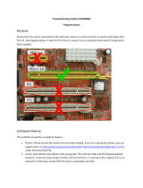
10
The Product key can
be found inside the
door of the
controller.
Computer Name:
It is recommended that only Internet-standard characters are used in the computer name. The standard characters are the
numbers 0 through to 9, upper and lower-case letters from A through to Z and the hyphen character. Computer names cannot
consist entirely of numbers, contain spaces or use special characters such as: < > ; : “ ?* + = \ | ? ,.
Step 7 - Windows®7 Setup
Start | Computer | Properties | Activate Windows now.
Select the appropriate method available.
To view the Product Key, open the front door panel. The Product Key label is displayed on the front panel of the system.
Step 8 - Activate Windows®7

Quick Start Guide
Quick Start Guide
11
All Datapath wall controllers have pre-congured settings for the wall layout and screen resolution. Change settings using the
TWIN tab:
Start | Control Panel | Appearance and Personalization | Adjust screen resolution.
1
2
3
Step 9 - Display Setup

Start | All Programs | Wall Control | Wall Control-My Computer
1
2 3
4
1 The Icons displayed in the application toolbar identify which type of source is available to each
input
2 Icons highlighted green indicate an active capture for that particular input.
3 Representation of the control screen if one is being used.
4 Representation of the video wall desktop.
Quick Start Guide
Step 10 - Wall Control (Optional)
Quick Start Guide
12

Quick Start Guide
To open a video window click and drag an active capture into the Wall Control application.
Use the Help Menu for a comprehensive guide on the features of the Wall Control application.
Quick Start Guide
13

Introduction
Chapter 1 - Introduction
1.1 Introduction
Congratulations on your purchase of the Datapath Wall Controller system. The wall controller has been manufactured and
tested to the highest standards oering unparalleled quality and reliability. The aim of this user guide is to assist you through
the installation of the system safely and eectively and act as a reference guide for future use. Do not switch on the system
until all the relevant cables have been connected.
1.2 Systems
The systems covered by this user guide are the VSN900 and the VSN1100 video wall controllers and expansion chassis ranges.
1.3 How the User Guide is Organised
The user guide is broken down into chapters and each chapter into sections. Chapters, sections and pages are numbered
individually. Pages are numbered in Arabic numerals with the exception of the cover page (no numbering).
1.4 Fonts and Symbols
1.4.1 Fonts
The font used throughout the user guide is Corbel however the following font styles mean:
Bold = Used to describe menu titles, buttons in software or elements that you must type exactly as shown in the Command Line
Interface
Ellipsis (...) - Parameter that can be repeated several times in a command line.
Between brackets ([]) - Optional items.
Between braces ({}) - Set of choices (separated by I) from which you must choose only one.
Italic = Information that must be supplied by the user
Courier = Indicates code or program output.
Blue Underlined = Indicates a hyper-link. Some hyper-links may be linked to live websites.
1.4.2 Symbols
Symbols are used throughout this user guide to assist the user in quickly identifying important safety information and notes.
Yellow triangle indicates that failure to observe the instructions could result in injury
and/or damage to the system.
Lifting precautions should be considered.
White arrow in a blue box indicates a useful tip.
White exclamation mark in a blue box indicates important information.
14

Introduction
1.5 Terminology and Denitions
1.5.1 Backplane
Datapath manufactures types of backplanes; the Express9 Gen 3 (9 slots) and the Express11 Gen 3 (11 slots).
The Express 9 Gen 3 is used in the VSN970/990 and the VSN900X expansion chassis and the Express 11 Gen 3 is used in the
VSN1170/1190 and the VSN1100X expansion chassis.
The backplanes use advanced PCI Express switches to create a high bandwidth fabric that connects up to 9 or 11 PCI Express
plug in cards in a single system. This system can be expanded to create more PCI Express slots using the VSN900x/1100X
expansion units.
1.5.2 BIOS
Basic Input/Output System: Used during system boot up to initialise and test system hardware and load the operating system.
Each BIOS is specically designed to work with a particular motherboard.
1.5.3 Command Line Interface
Preferred means by advanced users of issuing commands and controlling an application or operating system. Programs with a
Command Line Interface are generally considered easier to automate via scripting.
1.5.4 Control Screen
Some systems are shipped with the BIOS congured to boot the system o the onboard graphics device. This output can then
be used as the Control Screen for a typical video wall. The content of the control screen is not displayed on the video wall desk-
top and can be used to host the Wall Control application window.
1.5.5 SBC
A Single Board Computer built on a single circuit board. SBC’s in the VSN970/990/1170/1190 are plugged into the PICMG1.3 slot
on the Express9 and Express 11 backplanes
1.5.6 SDK
Software Development Kit: A set of software development tools which allows the creation of certain applications
1.5.7 Wall Control (Optional)
An optional software application for controlling and managing Vision, IP-Camera and third party application windows on a
Datapath Wall Controller. Providing a graphical representation of the video wall and a toolbar through which to manipulate all
available input sources and applications. Can also be used oine.
1.5.8 Wall Monitor
A software application that enables the user to monitor the temperatures and voltages of system components.
1.5.9 Screen Order
The order in which the screens appear on the display wall.
1.5.10 SQX
SQX is Datapath’s collective name for its video streaming and compression technologies.
15
Introduction

Safety
Chapter 2 - Safety
16
2.1 Safety Precautions
To prevent damage to your Datapath product or injury to personnel operating the equipment, please read the following safety
precautions prior to operation. These instructions should be made available to all those who will use and operate Datapath
products.
2.1.1 Power Supply
All Datapath products require a mains power supply. This power supply must be disconnected when equipment is being
upgraded or relocated.
2.1.2 Cables
Do not expose cables to any liquids; doing so may cause a short circuit which could damage the
equipment. Do not place heavy objects on top of any cables as this can cause damage and possibly lead to exposed live wires.
2.1.3 Ventilation
All computer equipment should be located in a well ventilated area. All ventilation holes on the computer casing must be kept
clear of any obstruction at all times. Failure to do so will result in the system over heating and damaging your equipment.
2.1.4 Working Environment
The equipment should be located in an environment free from dust, moisture and extreme changes in temperature and should
be placed on a stable and solid work surface. Liquids (hot/cold drinks etc) should not be placed near the equipment as spillage
could cause serious damage.
2.1.5 Gas/Flammable Liquids
Electronic equipment should never be used in the presence of gas or any ammable liquid, doing so could result in an explosion
or serious re.
2.1.6 Smoke/Unusual Smells
Should you notice smoke or unusual smells being emitted from your system, turn o and unplug the system from the mains
supply. The system should then be passed to a qualied technician for inspection. Continued operation could result in personal
injury and damage to property.
2.1.7 Maintenance
Apart from what is detailed in this user guide, maintenance should only be carried out by competent technicians, any Datapath
plug-in cards that are physically damaged should be returned to Datapath for repair using Datapath RMA procedures.
2.1.8 Replaceable Batteries
Caution: Risk of explosion if batteries are replaced by an incorrect type. Dispose of used batteries according to the local laws /
regulations and manufacturer’s instructions.

Safety
17
Safety
2.2 Rack Mount Safety Instructions
2.2.1 Temperature
If VSN900/1100 systems are to be installed in a closed or multi-unit rack assembly, the installation should be such that the
amount of air ow required for safe operation of the equipment is not compromised. The operating ambient temperature of the
rack environment should be maintained below 35 degrees centigrade under all conditions. Appropriate cooling arrangements
should be built into the cabinet to ensure that this specication is maintained.
2.2.2 Mechanical Loading
Mounting of the equipment in the rack should be such that a hazardous condition is not achieved due to uneven mechanical
loading.
2.2.3 Circuit Overloading
Consideration should be given to the connection of the equipment to the mains supply circuit and the eect that overloading
of the supply might have on any over-current protection or supply wiring. Appropriate consideration of equipment nameplate
ratings should be used.
2.2.4 Reliable Earthing
Reliable earthing of all rack-mounted equipment should be maintained. Particular attention should be given to supply
connections other than direct connections to the branch circuit (e.g. use of power strips).
2.3 Unpacking and Initial Inspection
2.3.1 Unpacking
The system is heavy; lifting precautions should be considered.
To unpack the system follow the instructions provided on the outside of the packaging. All packaging materials should be
retained for future transit.
2.3.2 Initial Inspection
All systems are carefully prepared for shipment and every eort is made to ensure you receive the product in pristine condition.
On receipt, you should carefully inspect the outer packaging for any transit damage i.e. any signs that the system may have
been dropped etc.
Use the packing list enclosed to establish that all the items are present. Should any items from the packing list be missing,
contact Datapath for further instructions.
Check the chassis for damage that could have an adverse aect on the operation of the system or could cause injury to the
operator. Should there be any physical damage to the power supply unit, for example damaged power sockets or exposed
wiring do not connect to a power source, contact Datapath for further instructions.

General
Chapter 3 - General
3.1 Overview
Datapath’s VSN900 and VSN1100 systems are powerful video wall controllers, capable of delivering Ultra High Denition video
across large, multi-screen display installations. For use in a host of environments, from CCTV security suites to sports stadia,
and from military installations to utility management centres. Fully compatible with Datapath’s world leading portfolio of PCI
Express video capture and graphics cards that oer Ultra High Denition video for storage and display, including the ability to
capture HDCP sources without any display restrictions.
Each system has been designed for use in demanding control room environments. Each component has been subjected to
rigorous testing to ensure the highest levels of performance and reliability.
In summary:
• High performance and reliability in demanding conditions
• Suited for 24/7 applications
• Can be operated via a network
• PCIe switched fabrics enables systems to be expanded using additional expansion chassis
• Wall Control software (optional) - Display video on the desktop in real time using an array of features
• Wall Monitor software (optional) - Provides monitoring of the temperature and voltage sensors on system components
3.2 Systems in the VSN900 and VSN1100 Range
Features
Systems
Express 9
Backplane
Express 11
Backplane
SBC 3 SBC 4 Intel® Core i7
Dual Intel® Core
Xeon
RPSU ATX
VSN970* x x x x x
VSN990 x x x x
VSN1170 x x x x
VSN1190 x x x x
VSN900X* x x x
VSN1100X x x
* Available with either and RPSU or ATX power supply.
3.3 Associated Output/Input Cards and Related Products
The following table lists the range of Datapath products associated with the VSN900/1100 range of video wall controllers:
Product Description
ImageDP4 Quad output DisplayPort graphics card.
ActiveSQX Dedicated IP Streaming decoding card.
VisionSC-DP2 Dual channel, 4K UHD DisplayPort capture card.
VisionSC-SDI4 Four channel 3G-SDI video capture card.
VisionSC-HD4+ Quad HDMI video capture card.
VisionAV-HD Four lane PCI Express capture card with 2 x HD DVI-I and 1 SD channels.
VisionAV-SDI Four lane PCI Express capture card with 1 x HD DVI-I, SD, SDI channels.
VisionHD4 Eight lane PCI Express capture card with four independent DVI-I HD channels.
18

General
VisionRGB-E1s Single channel HD video capture card.
VisionAV Single Channel HD and single channel SD video capture card.
VisionRGB-E2s Dual channel HD video capture card.
VisionDVI-DL Single channel Dual-Link video capture card.
VisionSD4+1s Video capture card with four channels of SD and one of HD.
VisionSDI2 Dual channel HD-SDI video capture card.
VisionSD8 Eight channel SD video capture card.
HLink-G3 Host link card for Gen.3 expansion systems.
SLink-G3 Slave link card for Gen.3 expansion systems.
ExCable-G3 Copper cable Gen.3 for expansion systems.
HLink-Optical Host link card for optical linked expansion system.
SLink-Optical Slave link card for optical linked expansion system.
ExCable-Optical Locking optical cable available in 50m and 100m lengths.
We are constantly updating our product portfolio, for the latest details on our full product range please visit our website:
www.datapath.co.uk
3.4 Product Datasheets
Product datasheets are available to download from www.datapath.co.uk
General
19

Hardware
Chapter 4 - Hardware
20
4.1 VSN970 / VSN1170 Chassis
4.1.1 Front
Front Panel
1 = Power, on-o 5= Reset Button
2= PSU Alarm Reset 6= USB Ports
3= Power LED 7= DVD +RW
4= HDD LED 8= Removable Hard Drives
4.1.2 Rear
Rear Panel - RPSU
Rear Panel - ATX
R1= Power Switch R3= Ethernet Ports
R2= USB Ports R4= DVI-I Output
1
3
2
4 5
6
7 8
R2
R1
R3
R4
R1
R2
R3
R4
/