Page is loading ...

Do not store or use gasoline or other
flammable vapors and liquids in the
vicinity of this or any other appliance.
An unconnected liquid propane
cylinder should not be stored in the
vicinity of this or any other appliance.
If you smell gas:
Shut off gas to the appliance.
Extinguish any open flame.
Open lid.
If odor continues, immediately call
your gas supplier or fire department.
Read all of these instructions and keep them in a safe place for future reference.
Leave these instructions with the consumer.
Assembly and Owner’s Manual
L.P. Gas
Cylinder
Not Included
Great Outdoors
the
TM
FOR YOUR SAFETY: Never leave a grill unattended when in use.
FOR YOUR SAFETY
1
2
1
2
3
4
CONSUMER / USER:
ASSEMBLER / INSTALLER:
FOR YOUR SAFETY
TG560
Portable
Gas Grill

4
4
4
5-7
8
22
23-24
9-21
Table of Contents
Chapte r 1 - INSTALLATION
Necessary Information . . . . . . . . . . . . . . . . . . . . . . . . . . .
Choosing a Safe Location . . . . . . . . . . . . . . . . . . . . . . . .
Portable L.P. Gas Grills . . . . . . . . . . . . . . . . . . . . . . . . . .
L.P. Gas Dealer Instructions . . . . . . . . . . . . . . . . . . . . . .
Installing an L.P. Gas Cylinder . . . . . . . . . . . . . . . . . . . . .
Connecting to Natural Gas . . . . . . . . . . . . . . . . . . . . . . .
Chapter 2 - ASSEMBLY INSTRUCTIONS
CFM Corporation
2695 Meadowvale Boulevard
Mississauga , Ontario L5N 8A3 Canada
(800) 668-5323
www.cfmcorp.com
Service Note: If you are experiencing difficulties or are dissatisfied with your purchase, please contact CFM at
the telephone number listed above prior to returning your grill to the store.
®
Formerly:
Now:

4
·
·
·
·
·
Operating this or any gas-fired appliance
in an enclosed area can produce a build-up
of carbon-monoxide, which could result in
injury or death.
or, in the absence of local codes, with
either the National Fuel Gas Code, ANSI
Z223.1, NFPA 54 (USA), or CAN/CGA-B
149.1 Natural Gas and Propane Installation
Code (Canada).
To check local codes, contact your local gas
dealer or gas company listed in the Yellow
Pages for recommended installation
procedures and regulations.
Do not use a grill under a ceiling or cover
where the heat or flame could cause
damage.
Choose a level surface where the grill is
not facing directly into the wind.
Avoid moving the grill during use.
Do not use lighter fluid or charcoal
briquettes in a gas grill. The flow of
combustion and ventilation air is not to be
obstructed. The ventilation openings of the
cylinder enclosure must be kept free and
clear from other debris. Do not store grill
covers or other items in the cylinder area.
· Do not operate this barbecue in garages,
breeze ways, sheds or any enclosed area.
Choosing a Safe Location
for a Gas Barbecue Grill
Necessary Information to
Safely Use a Gas Grill
Installation 1Chapter
Pinnacle Series Gas Grill
The gas fuel used by this product is
highly flammable and must be used in
a responsible and cautious manner.
It is your responsibility to assemble,
operate, and maintain your gas
barbecue grill properly.
If these instructions are ignored, there
is a possibility of a hazardous fire or
explosion which could result in proper-
ty damage, physical injury or death.
2. Installation must conform with local
codes
3. This appliance is not intended to be
installed in or on a recreational vehicle
and/or boat.
4. Keep the barbecue grill at least 24
inches (61 cm) away from any combustible
construction.
5. The grill area must be clear and free from
combustible materials, gasoline, and any
other flammable liquids or vapors.
1. The gas barbecue grill may only be used
for cooking out-of-doors.

5
The L.P. Fuel Supply SystemThe L.P. Fuel Supply System
Hot drippings from cooking food could
damage the fuel supply system.
Liquid Propane (abbreviated L.P.) gas is
stored under high pressure inside a cylinder
and will vaporize when released. It is
important that there are no leaky
connections on the grill fuel supply system.
Refer to the Leak Testing section of this
manual.
An L.P. gas grill requires a fuel delivery
system made up of a L.P. gas supply
cylinder, a fuel regulator with hose and a
gas-control valve.
·
L.P. Gas
The L.P. Fuel Supply System
Do not store an L.P. cylinder in a building,
garage or any other enclosed area. Instead,
store the cylinder outdoors in a well
ventilated area, away from people and out of
the reach of children.
Place your barbecue grill in a location
away from children and pets.
Do not leave grill unattended when in use.
To avoid burns, do not touch any hot grill
surface. If necessary, use a protective glove
when operating control knobs, tank shut-off
valve, or lid handle.
Do not place combustible material, such
as cloth or plastic, on grill surface during
use.
Do not lean on side tables or place more
than 15 pounds of weight on a side table.
·
·
·
·
·
Portable L.P. Gas
Barbecue Grills
9. Make sure that the drip pan is in place
under the grill bottom.
Do not use natural gas in an
appliance designed for L.P. gas. Use only
liquid propane (L.P.) gas in an appliance
designed for L.P. Gas.
NEVER leave a grill
unattended when in use.
IMPORTANT:
WARNING:
6. Do Not store a spare L.P. gas cylinder
under or near this appliance.
7. NOT FOR USE BY CHILDREN.
8. The outside of the barbecue grill will
become hot during use.

6
4. The pressure regulator and hose
assembly provided is factory set at an outlet
pressure of 11 inches water column (.4 lb.
per sq. Inch).
L.P. Cylinders can be obtained at the store
where you purchased your grill or from an
authorized L.P. gas dealer.
Any L.P. gas-supply cylinder used with this
grill must be approximately 12 inches
diameter and 18 inches high.
L.P. GAS SUPPLY CYLINDER
L.P. GAS CYLINDER SPECIFICATIONS
The maximum
fuel capacity must be 20 pounds of propane.
Full-cylinder weight should be approximately
38 pounds (43.7 lbs. Nominal water
capacity).
FUEL REGULATOR AND HOSE
The fuel regulator supplied is equipped with
a Type 1 coupling nut. Do not attempt to
connect to any other L.P. cylinder not
equipped with a mating Type 1 cylinder
valve. This grill is not to be used with any
other cylinder connection device.
The fuel regulator and hose assembly with
the Type 1 fitting supplied must be used with
the appliance. Do not use a hose and
regulator assembly other than the one
supplied with the grill or a manufacturer’s
replacement fuel pressure regulator
assembly.
The Type 1 connection system has the
following features:
1. The system will not allow gas to flow until
a positive connection has been made.
2. The system has a thermal element that
will shut off the flow of gas between 240°F
and 300°F.
3. The system has a flow-limiting device
which, when activated, will limit the flow of
gas to 10 cubic feet per hour.
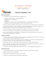
The L.P. Fuel Supply System
(the fuel regulator and hose)
Fuel Supply
Hose
Sideburner
Valve
Type 1 Fuel
Regulator
Multiple Burner
Fuel-Control Valves
The L.P. Fuel Supply System
(L.P. gas cylinder)
L.P. Gas
Cylinder
Cylinder Control
Valve
Any attempt to adjust the
regulator is dangerous and could create a
situation causing personal injury or property
damage. Consult your L.P. gas dealer if you
think the regulator is not working properly.
WARNING:
NOTE:
L.P. Gas
Cylinder
NOT
INCLUDED

7
Have the gas dealer weigh the cylinder
after filling to ensure that the cylinder is not
overfilled.
TRANSPORTING A FULL CYLINDER
You should transport only one cylinder at a
time. Transport the cylinder in an upright and
secure manner with the control valve turned
off and the dust cap in place.
Do not transport a cylinder in the passenger
compartment of a vehicle.
Do not leave cylinder in direct sunlight or in
a high-heat area such as a closed car trunk.
High-heat areas could cause the relief valve
to vent gas.
Use a cylinder cap on the cylinder-valve
outlet during transport and when the cylinder
is not connected to the grill. Keep cylinder
valve closed when not in use.
The L.P. gas cylinder must have a shut-off
valve
AType 1 compatible
cylinder with a Type 1 cylinder valve has a
positive seating connection that does not
permit gas flow until a positive seal has been
obtained.
The cylinder must be arranged for vapor
withdrawal. It must also include a collar to
protect the cylinder valve. A safety-relief
device having direct communication with the
vapor space of cylinder must be provided.
This will expel high-pressure gas if the
cylinder is overfilled or overheated.
All L.P. gas cylinders used with this
appliance shall be constructed and marked
in accordance with the specifications for L.P.
gas cylinders of the U.S. Department of
Transportation (DOT) or the National
Standard of Canada, CAN/CSA-B339,
Cylinders, Spheres and Tubes for
Transportation of Dangerous Goods; and
Commission, as applicable; and shall be
provided with a listed overfilling-prevention
device. Read labels on the L.P. gas-supply
cylinder.
Inform the gas dealer if it is a new or used
cylinder to be filled. Caution the gas dealer
not to overfill the fuel cylinder.
After filling, have the gas dealer check for
leaks and that the relief valve remains free to
function.
Allow only a qualified L.P. gas dealer to
fill or repair an L.P. gas-supply cylinder.
terminating in a Type 1 L.P. gas-
cylinder-valve outlet.
a.) Do not store a spare L.P. gas cylinder
under or near this appliance.
b.) Never fill the gas cylinder beyond 80
percent full.
c.) If the information in (a.) and (b.) Is not
followed exactly, a fire causing serious
injury or death may occur.
Handle a full cylinder with care.
Gas is under high pressure.
DANGER:
WARNING:
Do not insert any foreign objects
into the valve outlet. You may damage the
back check, A damaged back check can
cause a leak, which could result in explosion,
fire, severe personal injury or death.
DANGER:

8
The L.P. gas cylinder has a Type 1 cylinder
valve with a back-check module in its outlet
that will not permit gas to flow until an
evacuation device is installed. To purge the
L.P. gas cylinder, the back-check module must
be opened with an evacuation device.
A. Hose-end valve with a bleed port: Purging
can be accomplished using a hose-end valve
containing a bleed port, which also allows for
evacuation without the use of an adapter.
B. Hose-end valve without a bleed port:
When a hose-end valve does not have a bleed
port, a separate device must be used for
evacuation.
C. Purging using a Type 1 connection: L.P.
gas cylinder evacuation can be accomplished
during each purging by using a Type 1
connection. The Type 1 valve outlet has 1-
5/16” external ACME right-hand thread that will
accept this connection.
After purging or filling an L.P. gas
cylinder, do not insert a POL plug into the
valve outlet. Insertion of this plug will prevent
the back-check from closing. Use ONLY the
provided cap and strap attached to the outlet.
Close the cylinder valve knob before returning
the cylinder to the customer.
For proper purging procedures in the USA,
refer to: Safety Bulletin NPGA # 133, “Purging
L.P. Gas Cylinders,” and Safety Bulletin NPGA
#130, “Recommended Procedures for Filling
Cylinders.”
PURGING AND EVACUATION DEVICES
FOR L.P. GAS CYLINDER WITH TYPE 1
CYLINDER VALVES
CAUTION:
When using a cylinder exchange, be sure
the exchanged cylinder is a Type 1 cylinder;
a 510 POL cylinder will not fit a Type 1
regulator.
Purge new cylinders before
filling. This tank is easily filled with a standard
CGA 510 POL filling connection.
FILLING AND PURGING
TYPE 1 L.P. GAS CYLINDERS
IMPORTANT:
Example B
Type 1
(cut away to see fitting)
Filling a Type 1 Cylinder Valve
Example A: shows a CGA-510 POL fitting.
Example B: shows using a Type 1 POL fitting.
Example A
CGA-510 POL
Take These Instructions to the L.P. Gas Dealer
Do not fill an L.P. gas cylinder
beyond 80% full. If this information is not
followed exactly, a fire causing serious injury
or death may occur.
DANGER:
Purging and filling of L.P. gas
cylinders must be performed by personnel who
have been thoroughly trained in accepted L.P.
gas industry procedures. Failure to follow this
instruction may result in explosion, fire, severe
personal injury or death.
DANGER:

9
Getting Started
1. Please follow the steps in the order that
they are presented.
2. Assemble the grill where you plan to use
it.
3. You may want to place an old towel or
cloth at the assembly site to prevent nuts
and bolts from becoming lost.
4. Some parts have sharp edges - gloves
are recommended when handling parts.
5. Have a friend help. An assistant can
make the assembly easier by holding the
parts in place while you fasten the nuts and
bolts.
6. To be ready to barbecue immediately,
have the L.P. gas cylinder filled by an
authorized L.P. dealer or cylinder exchange
center.
Unpacking the Grill Parts
1.
2. Remove and set aside all inner boxes
and parts from the master carton. Be sure to
remove all parts packed under the grill lid.
3. Remove and set aside all wrapping
paper and additional packaging from the
parts. Open all cartons and bags and lay the
parts out for easiest access. Refer to pages
34 and 35 for parts and hardware details.
A box knife may be necessary to open
cartons and bags.
4. Do not destroy carton or packing until
your grill is completely assembled and
operating to your satisfaction.
5. Most stainless panels are covered with a
clear protective sheet - this clear protective
sheet must be removed before use.
Phillips-head screwdriver (magnetic)
Pliers or adjustable wrench
Estimated time for assembly: 70 minutes.
Tools needed to assemble grill:
·
·
(tools not included)
Assembly Instructions 2Chapter
Pinnacle Series Gas Grill

HARDWARE:
M5x10mm Screw
M6x15mm Bolt
M6x40mm Bolt
M6 Nut
1/4-20
Thumb
Screw
B
B
C
C
D
D
C
D
E
E
A
A
Figure A: (L.P. Gas Models Only)
Step 1:
Step 2:
Step 3:
Step 4:
Step 5:
Step 6:
Attach the drawer slides (58) to the tank holder (57)
using four M5 screws (A) as shown. Ensure that the ends
of the drawer slides are flush with the front of the tank
holder. Loosely tighten the screws.
Attach the tank drawer assembly (from step 1) to
the bottom panel (47) using four M6 bolts (B) as shown.
Insert the thumb screw (E) into the tank holder (57)
as shown. It does not need to be tightened at this time.
Align two legs (48) to the corners of the bottom
panel (47) as shown. The side panel (49) wraps around the
outside of the legs.
From the back side of the assembly, insert one M6
bolt (C) through the side panel (49), leg (48) and bottom
panel (47), and thread a M6 nut (D) to the bolt (C) from the
inside. Loosely tighten the bolt.
From the front side of
the assembly, insert two M6
bolts (C) through the right
door mount (55), then
though the
s
s
Loosely tighten the screws. Once all screws are in place
from steps 1 and 2, tighten them securely.
side
panel (49), leg (48) and
bottom panel (47), and
thread M6 nut (D) to the
bolt (C) from the inside.
Loosely tighten the bolts.
Repeat Step 6 for
the left side panel, legs, and
door mount (52)(see index page 34).
The door mounts are specific to left
and right - the item shown (55) is for
the right side. The legs and side panels
are not specific to left and right.
Figure B:
Step 7:
58
57
47
47
55
48
48
49
Figure A
(L.P. Gas
Models
Only)
Figure B
Front
Back
10

HARDWARE:
Snap
Bushing
M6x15mm
Bolt
M6x40mm Bolt
M6 Nut
B
B
F
B
B
B
B
C
C
D
C
D
F
54
51
Figure C
Figure D
Front
Front
Back
Step 9
Step 9
Figure C:
Step 8:
Step 9:
Step 10:
Step 11:
Step 12:
Attach the back panel (54) to
the back of the cart assembly as
shown. Use two M6x15mm bolts (B)
to secure the top, and two M6x40mm
bolts (C) to secure the bottom as
shown. Thread M6 nuts (D) to the
lower bolts. Loosely tighten the bolts.
Insert M6x15mm bolts (B)
into the side panel holes as shown.
Loosely tighten the bolts.
Insert the snap bushing (F)
into the access hole of the back panel
(54).
Attach the front cross bar
(51) to the front of the assembly as
shown. Use six M6 bolts (B) to secure
the front cross bar. Insert and loosely
tighten all bolts first.
Once all bolts are in place,
securely tighten ALL bolts from all
previous steps.
Figure D:
B
11

HARDWARE:
M6x15mm Bolt
M3.5 Nut
M3.5x6mm Screw
B
G
G
H
H
B
B
H
G
50
50
50
50
62
61
Figure E
Figure F
Front
Figure E:
Step 13: Attach the outer drawer tracks (61 & 62) to the
support brackets (50) as shown using M3.5 screws (G)
and M3.5 nuts (H). Securely tighten the screws.
The support brackets are not specific to left or right. The
drawer tracks are specific to left (62) and right (61), but
not relevant to this step. Refer to the following steps
and Figure F for left and right placement of the drawer
tracks.
Figure F:
Step 14: Mount the support
brackets (50) to the top of the cart
assembly as shown. Be sure the
drawer tracks are properly located
as left and right as shown.
Use four M6 bolts (B) to secure the
support brackets. Securely tighten
the bolts.
Left
Left
Right
Right
12

Figure H:
Figure J:
Step 16:
Step 17:
Attach a door handle (66) to a cabinet door (53) using two M4
screws (J). Firmly secure the screws, but be careful not to strip the
threads in the plastic handle.
Repeat step 16 for the remaining cabinet door (56) and handle (66)
.
Attach the drawer handle (67) to
the drawer (60) two
(see
index page 34)
using M4 screws (J).
Firmly secure the screws, but be careful
not to strip the threads in the plastic
handle.
Mount the inner drawer
tracks (63 & 64) to the drawer as
shown using M3.5 screws (G)
and M3.5 nuts (H). Securely
tighten the screws.
The inner drawer tracks are
specific to left (64) and right (63).
Step 18:
13
HARDWARE:
M4x6mm Screw
M3.5 Nut
M3.5x6mm Screw
J
J
J
G
G
H
G
J
H
G
53
60
66
67
65
68
68
65
Figure G
Figure H
Figure J
Front
Figure G:
Step 15: Insert the four casters (65 & 68) into
the bottom of the leg posts as shown. The two
locking casters (65) go in the front, the two
non-locking casters (68) go in back. Press the
caster stems firmly into the mounting holes.
63
64
Right
Left

Figure L:
Step 21: Place the drawer assembly (from
step18) into the drawer tracks.
Figure M:
Step 22: Install six control knobs (26) onto the
control panel by pushing them on to the valve
stems as shown.
HARDWARE:
Nylon
Washer
K
K
K
53
56
55
52
Figure K
Figure L
Figure K:
Step 19:
Step 20:
Place the nylon
washers (K) onto the lower
door mounts (52 & 55).
Mount the doors
(53 & 56) to the lower door
mounts (52 & 55).
The holes in the doors slide over
the lower door mount hinges
(see Figure K1).
The pins in the top of the doors
are spring-loaded - push the
pins in and snap them into the
upper door hinge tab. (see
Figure K2)
Note: doors can be adjusted by
loosening and adjusting the
lower door mount hinges
(52&55) as necessary.
Right
Left
Figure K2
Figure K1
14
Figure M
26

HARDWARE:
M5x10mm Bolt
L
Figure N
Figure N:
Step 23:
Step 24:
Set the grill head (21) onto the cart assembly.
Before securing the grill head, route the gas
hose though the cut-out portion of the mounting bracket
(50) as shown in Figures M1 and M2. The regulator (a)
must be inside the cabinet. The side burner valve (b)
must be outside the cabinet. It may be necessary to pull
the drawer out for easier access.
Caution: the grill head is heavy - be sure to get
assistance.
Figure N1
Figure N2
a
a
b
b
L
L
50
15
Figure O:
Step 25: Secure the grill head (21)
to the cart assembly using four M5
bolts (L) at the four corner
mounting locations shown.
Securely tighten the bolts.
Be sure the side burner valve (b) is
routed out the right side of the
cabinet and the regulator (a) inside
the cabinet. Eliminate any kinks or
binding in the hose.
Figure O
21
21
21
21

Figure P:
Step 26: Remove the four screws (B)
from the left side table (28) indicated
as shown. Do not discard the screws
- they will be used in the next step.
Figure Q:
Step 27:
Step 28: -
Mount the left side
table bracket (30) to the left side
table (28) as shown, using two
of the screws previously
removed in step 25. Securely
tighten the screws.
Mount the left side
condiment tray (29) to the left
side table (28) as shown.
Secure the tray the
remaining
using two
screws previously
removed in step 25. Securely
tighten the screws.
16
Figure P
28
B
B
B
B
Figure Q
28
29
30
39
32
Figure R
Figure R:
Step 29: Locate the igniter unit (39). Unscrew the igniter
button and mounting ring from the igniter module by
turning it counter clockwise while holding the main body of
the igniter module steady.
Insert the main body of the igniter module from the back
of the right-side condiment tray (32) as shown. Secure the
igniter module with the mounting ring, then re-attach the
igniter button by screwing it back onto the igniter module,
turning it clockwise until it is snug. Note: Do not over
tighten button - it will slip on the threads. In which case,
simply re-tighten the button until snug.

17
Figure S1, S2 & S3:
Step 30: Remove the two screws (A) from the
side burner valve (b) indicated as shown. Do
not discard the screws - they will be used in
the next step.
Step 31: Attach the side burner valve (b) and
knob bezel (25) to the right side condiment tray
(32) as shown. Use the two screws previously
removed in step 28 to secure the valve and bezel
to the tray.
Securely tighten the screws then push the burner
knob (26) onto the valve.
Following step 30, the back of the right-side
condiment tray should look as shown in figure S3.
Note: The terminal posts on the igniter must be
oriented closest to the valve.
Figure S2
Figure S3
32
25
26
b
Back
Terminal Posts
Figure
S1
A
A
b
Figure T:
Step 32: Remove the four screws (B) from
the side burner table (31) indicated as
shown. Do not discard the screws - they will
be used in the next step.
Figure T
31
B
B
B
B

18
Figure V:
Step 35: Loosen and remove the nut and washer
used to attach the electrode (36) as shown, being
careful not to let the screw fall out the other side. Use
the ground wire (40) found in the kit, and slip the
eyelet of the ground wire over the open end of the
screw. Re-attach the nut and washer, and tighten
securely.
Locate the electrode wire (5a) in your kit and attach it
to the end of the electrode.
40
36
5a
Figure W:
Step 36: Attach the ground wire and the electrode
wire to the terminals on the back of the igniter as
shown.
Note: It does not matter to which terminal each
wire is attached, as long as each wire makes a
good connection.
Figure V
Figure WFigure W
Figure U:
Step 33:
Step 34:
Mount the right side table bracket (33)
to the side burner table (31) as shown above,
using two of the screws previously removed in
step 30. Securely tighten the screws.
Mount the right side condiment tray
(32) to the side burner table (31) as shown
above. The side burner valve (b) must be
inserted into the end of the burner tube (c).
Secure the tray the remainingusing two screws
previously removed in step 30. Securely tighten
the screws.
Note: The shutter cap on the end of the burner
tube (c) may require tightening of the screw. The
burner shutter opening should be adjusted to
meet ideal flame character as described on
page 31.
Figure U
32
31
33
b
c

Figure X
Figure X:
Step 37: On the side of the
grill tub, locate the four
bolts indicated by the
arrows shown. For bolts
marked as "A", loosen
them about half way and
leave them threaded into
the grill tub.
For the bolt marked as "B",
remove it and set it aside.
Do not discard the bolt - it
will be used in the next
step.
Figure Y:
Step 38: Mount the side
table to the side of the grill
tub as shown. The
mounting holes slide over
and down onto the bolts.
Using the bolt removed
previously, insert it into the
front of the table as shown
and thread it into the grill
tub.
Securely tighten the bolts.
Repeat steps 37 and 38 for
the remaining side table.
19
A
A
A
B
Figure Y

45
24
27
Figure Z
Figure AA
Figure Z:
Step 39: five
(24)
Insert the heat
shields into the grill tub.
Each heat shield must be
placed above a burner, resting
on the brackets in the front and
rear of the grill tub.
Place the cooking grid
onto the top of the grill tub. will rest
just inside the top ledge of the tub.
Step 40: two s (27)
They
Figure AA:
Step 41: Set the warming rack (45) on the
upper ledge of the grill tub.
Figure BB:
Step 42: Slide the grease pan (46) into
the rear of the grill as shown. Slide it
forward until it drops into place.
Figure BB
20
46

Figure :
Step 45: To install an L.P. gas
cylinder, set the cylinder into
the tank holder tray in the
bottom of the cart.
Tighten the thumb screw (E)
to secure the tank.
Note: L.P. gas cylinder not
included.
Hose attachment instructions
are on the following page.
DD
(L.P. Gas Models
Only)
21
Figure CC:
Step 43:
Step 44:
Place the drip cup (20) into the
drip cup holder (19).
Hang the drip cup holder (19)
from the grease pan (46) drain hole
underneath the grill tub, inside the
cabinet. The warming drawer
may need to be pulled out
to access the area.
Figure CC
Figure CC1
20
19
19
46
E
Figure
(L.P. Gas Models Only)
DD
/