319U46EN
E
N
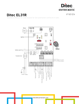
CONTROL PANEL
FOR 230 V GEARMOTORS
Installation manual
ZA3N

p.
2
2 - Manual
319U46EN
319U46EN v.
3
3- 07/2015 - © Came S.p.A. - The manual's contents may be edited at any time without notice.
The overall power of the motors must not exceed 600W.
4 Description
2.1 Intended use
1 Legend of symbols
This symbol tells you what to say to the end-users.
This symbol tells you that the sections concern safety issues.
This symbol tells you what to say to the end-users.
2 Intended use and restrictions
The ZA3N control panel is designed to control the 230V ATI, FERNI, KRONO, FAST and FROG swing gate operators.
The use of this product for purposes other than those described above and installation executed in a manner other than as
instructed in this technical manual are prohibited.
3 Reference standards
“IMPORTANT INSTALLATION, SAFETY INSTRUCTIONS”
“CAUTION: IMPROPER INSTALLATION MAY CAUSE SERIOUS DAMAGE, FOLLOW ALL INSTALLATION INSTRUCTIONS CAREFULLY”
“THIS MANUAL IS ONLY FOR PROFESSIONAL OR QUALIFIED INSTALLERS”
2.2 Limits to use
For its quality processes management CAME S.p.A. is ISO 9001:2008 certified, and for its environmental management it is ISO
14001:2004 certified. CAME engineers and manufactures all of its products in Italy.
This product complies with the following standards: see declaration of conformity.
This product is engineered and manufactured by CAME S.p.A.
and complies with current safety regulations.
The control panel works on 230V a.c. of power, 50/60Hz
frequency.
The control devices and accessories are powered by 24V.
Warning! The accessories must not exceed 20W overall.
All connections are protected by fast fuses, see table.
The board performs and controls the following functions:
- automatic closing after an opening command;
- pre-fl ashing of the fl ashing light;
- obstacle detection when gate is not running at any point;
- adjusting the motor torque on the connected automation
device;
- ram blow in opening phase.
The command modes that may be defi ned are the following:
- opening/closing;
- opening/closing with maintained action;
- partial opening;
- complete stop.
Following an obstacle detection, the photocells can:
- reopening if the gate is closing;
- reclosing or partial stop if the gate is opening;
- partial stop if the gate is opening.
Expressly fi tted trimmers adjust:
- duration of theautomatic closing;
- M2 gearmotor closing delay;
- operating time.
It is also possible to connect:
- signalling lamps - gate open;
- cycle lamp;
- electric lock.
FUSES TABLE
protection: fuse for:
Control board (line)
5A-F
Control devices and accessories
(control unit)
3.15A-F
TECHNICAL FEATURES
power supply 230V - 50/60Hz
max power 600W
power draw when idling
60 mA
max power of 24V accessories 20W
insulation rating
casing material ABS
casing protection rating IP54
operating temperature -20 / +55°C

L1 L2
U V W X Y E E3 10 11 S 1 2 3 3P 4 5 7 2 C1 CX B1 B2
L1T
CT 0 12 24
L2T
L2T L1T1234
0
12 24
(mm)
1
2
3
4
5
6
7
8
9
11
12
13
10
p.
3
3 - Manual
319U46EN
319U46EN v.
3
3- 07/2015- © Came S.p.A. - The manual's contents may be edited at any time without notice.
4.1 Dimensions, spans and anchoring holes
4.2 Main components
Warning! Before acting on the machinery,
cut off the main power supply.
* Found in the 230V FROG box. Connected them
up to the black (M1 motor) cables and red (M2
motor) cables fitted on the card; when coupling
with Ati, Fast, Ferni and Krono devices the cables
are not used because the condensers are already
connected up inside.
3 - Connection terminal boards
2 - Line fuse 5A
3 - Control unit fuse 3,15A
4 - Power up LED indicator 24V
5 - Buttons for memorising the radio code
6 - Operating time adjustment trimmer
7 - Trimmer for adjusting the automatic closure
time
8 - Trimmer for adjusting the delay of M2 during
closing and partial opening
9 - 10 DIP - Function selection
10 - Radio frequency card plug-in (see table)
11 - Signalling LED
12 - Torque limiter
13 - Condensers*
Black
White
Red
Orange
Blue
Violet
Red
Black

p.
4
4 - Manual
319U46EN
319U46EN v.
3
3- 07/2015 - © Came S.p.A. - The manual's contents may be edited at any time without notice.
Before installing, do the following:
• Check that the panel’s anchoring point is protected from possible blows, and that the anchoring surface is solid. Also check that the
anchoring is done using the appropriate bolts, screws etc.
• Make sure you have a suitable omnipolar cut-off device with contacts more than 3 mm apart, and independent (sectioned off) power
supply.
•
Make sure that any connections inside the case (that provide continuance to the protective circuit) be fitted with extra insulation
as compared to the other conductive parts inside.
• Make sure you have suitable tubing and conduits for the electrical cables to pass through and be protected against mechanical
damage.
Make sure you have all the tools and materials you will need for the installation at hand to work in total safety and compliance with the
current standards and regulations.
Fix the base of the panel in a protected area; we suggest using round
top Phillips recessed head screws of max. 6mm in diameter.
5.3 Fixing and mounting the casing
Perforate the pre-punched holes and insert the cable glands with
the corrugated tubing for the electrical cables to travel through.
N.B.: the pre-punched holes have the following diameters: 23, 29
e 37 mm.
Be careful not to damage the control board inside the control
panel!!
After the adjustments and settings, fix the cover using the provided
screws.
5 Installation
5.1 Preliminary checks
5.2 Tools and materials

56789 %%
FROG
FERNI
KRONO
FROG
FERNI
KRONO
FAST
ATI
ATI
,
,
3
M1
M2
FAST
p.
5
5 - Manual
319U46EN
319U46EN v.
3
3- 07/2015- © Came S.p.A. - The manual's contents may be edited at any time without notice.
6 Electrical connections
Accessories power supply
230V A.C. 50/60 Hz
control panel power supply
Terminal board for 24V A.C.
accessories power supply
Electrolock connection
(12V - 15W max)
When using only one motor (e.g. on one leaf gates), connect it up on W X Y (M2) regardless of
which side it is installed on – (fro FROG, if need be, invert connections X and Y).
Standard opening setup scheme in Came gearmotors.
Gearmotor featuring delayed action
on opening (M1)
Gearmotor featuring delayed action
on closing (M2)
Gearmotor

4 1
$
$9 # #
6789: &&
4 1
$
$9
p.
6
6 - Manual
319U46EN
319U46EN v.
3
3- 07/2015 - © Came S.p.A. - The manual's contents may be edited at any time without notice.
Signalling and lighting devices
Open gate light-indicator (Socket rating: 24V - 3W max.). Turns on
when the gate is open. It turns o when the gate is closed.
Flashing light (Socket rating: 230V A.C. - 25W max.)
- Flashes during opening and closing phases.
Cycle lamp connection (230V-60W)
This lamp lights up the vehicle manouvering
area and stays on from the moment the gate
leaves start opening until total stop takes
place (including automatic closing time). If
the automatic closure is not inserted it stays
lit up only while it is moving.
Control devices
Stop button ( N.C. contact)
- Gate stop buttom excluding automatic closing cycle; to start up movement
again press the command button or the transmitter button. (Bridge if unused)
Keyswitch and/or open button (N.O. contact)
- Gate opening command.
Keyswitch and/or comand button (N.O. contact)
- Gate opening/closing command. By pressing the button or
turning the selector key, the gate inverts is movement or stops
depending on the choice you have made on the Dip-switch (see
selecting functions, Dips 2 and 3).
Keyswitch and/or partial open button (N.O. contact)
- One gate leaf opening command to allow pedestrian passage (M2
opens).
Keyswitch and/or close button (N.O. contact)
- Gate closing command.

4 1
$
$9
TX
RX
4 1
$
$9
TX
./ # .#
RX
DIR
Delta-S
Delta
# #8
# #8
p.
7
7 - Manual
319U46EN
319U46EN v.
3
3- 07/2015- © Came S.p.A. - The manual's contents may be edited at any time without notice.
(N.C.) contact for «partial stop»
- Input for safety devices such as photocells, sensitive edges and other EN 12978-compliant
devices. Gate leaves are stopped if in motion, with consequent setup of automatic closing.
Dip 8 OFF - 10 ON
If unused set DIP switch n.8 to ON
(N.C.) contact of «re-closing during opening»
- Input for safety devices such as photocells, sensitive edges and other EN 12978-compliant
devices. During the gate leaves closing phase, opening the contact causes movement inversion
until fully closed.
Dip 8 OFF - 10 OFF
Safety devices
(N.C.) contact for «re-opening during closing»
- Input for safety devices such as photocells, sensitive
edges and other EN 12978-compliant devices. During the
gate leaves closing phase, opening the contact causes
movement inversion until fully opened.
If unused set DIP switch n.9 to ON
(N.C.) contact for «re-opening during closing»
(N.C.) contact for «re-closing during opening»
(N.C.) contact of «partial stop»
Or
Or

ON
OFF
/.
- -
6789: &&
4 1 $ $9 # #
-5
$5
-5
- -
6 7 8 9 : & & 4 1
$
$9 # #
-5
$5
-5
4#!
42-
4,
p.
8
8 - Manual
319U46EN
319U46EN v.
3
3- 07/2015 - © Came S.p.A. - The manual's contents may be edited at any time without notice.
7 Selecting functions
DIP-SWITCH 10 WAYS
8 Adjustments
1 ON Automatic closing activated (1 OFF-disactivated);
2 ON “Open-stop-close-stop” function with button (2-7) and radio control (with built-in AF card) - activated;
2 OFF “Open-close” function with button (2-7) and transmitter (with built-in AF card) - activated;
3 ON “Open only” function with transmitter (built-in AF card) - activated (3 OFF-disactivated);
4 ON Pre-Flashing during opening and closing – activated (4 OFF- disactivated);
5 ON Obstacle detection - activated (5 OFF- disactivated);
6OFF “Maintained action” (the transmitter cannot work) deactivated (6 ON - activated);
7 ON Ram blow activated; at each opening command, the gate leaves press when against the closing jamb for a second,
helping to release the electro-lock connected up on terminals 11-S. It is active only if the leaves are closed and
when operating time is over, or upon the 1st run after powering up the system;
8 OFF - 10 OFF Re-close during opening function (connect the safety device on 2-CX) - activated;
8 OFF - 10 ON Partial stop function (connect the safety device on 2-CX) - activated (if the devices on 2-CX are not used, set the
DIP 8 in ON);
9 OFF Re-open during closing function - activated; connect the safety device on 2-C1 (if the device on 2-CX is not used,
et the DIP in ON).
Trimmer T.L. = Adjusting the working time from 10” to 120”.
Trimmer T.C.A. = Adjusting the automatic closing from 1” to 120”.
Trimmer TR2M = Adjusting the M2 closing delay (min. 0”, max. 15”) and simultaneous partial opening (min. 0”, max. 30”).

,4 ,4
-5
$5
-5
" "
TOP TAM
p.
9
9 - Manual
319U46EN
319U46EN v.
3
3- 07/2015- © Came S.p.A. - The manual's contents may be edited at any time without notice.
9 Motor torque limiter
To vary the motor torque, shift the shown faston to
one of the 4 positions: 1 min., 4 max.
Only for cards marked on the table:
- place the jumper as shown depending on the series of transmitters used. (see diagram).
10 Activating the radio control
Connect the antenna’s RG58 cable to
the apposite terminals.
Antenna
Radio frequency card
Possible output of the radio receiver’s
second channel (N.O. contact).
Socket rating: 5A-24V D.C.
Frequency/Mhz
Radio
frequency card
Transmitters series
FM 26.995 AF130 TFM
FM 30.900 AF150 TFM
AM 26.995 AF26 TOP
AM 30.900 AF30 TOP
AM 433.92 AF43S / AF43SM TAM / TOP
AM 433.92 AF43TW TWIN (KeyBlock)
AM 433.92 AF43SR ATOMO
AM 40.685 AF40 TOUCH
AM 863.35 AF868 TOP

- -
6 7 8 9 : & & 4 1 $ $9 # #
-5
$5
-5
ATOMO
AT01 • AT02
AT04
CAME
CAME
CAME
TOUCH
TCH 4024 • TCH 4048
TOP
TOP-432A • TOP-434A
TOP-302A • TOP-304A
TAM
T432 • T434 • T438
TAM-432SA
CAME
CAME
CAME
C
A
M
E
C
A
M
E
CA
M
E
CAM
E
CAME
CAME
CAM
E
CAME
CAME
CA
M
E
TWIN
TWIN2 • TWIN4
TFM
T132 • T134 • T138
T152 • T154 • T158
TOP
TOP-432NA • TOP-434NA
TOP-862NA • TOP-864NA
TOP-432S
p.
10
10 - Manual
319U46EN
319U46EN v.
3
3- 07/2015 - © Came S.p.A. - The manual's contents may be edited at any time without notice.
AF card
Lock the radiofrequency card into the electronic card AFTER CUTTING OFF THE POWER SUPPLY (or after disconnecting the batteries).
N.B.: The control board only recognises the radiofrequency card when the power is on.
Transmitters
see attached instructions
see instructions attached to
AF43SR card

- -
6 7 8 9 : & & 4 1 $ $9 # #
CH1 CH2
p.
11
11 - Manual
319U46EN
319U46EN v.
3
3- 07/2015- © Came S.p.A. - The manual's contents may be edited at any time without notice.
1) Keep the CH1 button on the electronic card
pressed. The LED fl ashes. Press the transmitter
button you wish to memorise. The LED will stay on to
show memorisation has been successful.
2) Perform the same procedure with the CH2 button
coupling it to another button on the transmitter.
CH1 = Channel for direct command to a function of the the gearmotor’s card, (“open only / “open-close-invert” or “open-stop-close-stop”
command, depending on the choice made on DIP switches 2 and 3).
CH2 = Channel for direct command an accessory device connected to B1-B2.
Memorisation
Intermitting LED
AF radio frequency
card
11 Phasing out and disposal
In its premises, CAME S.p.A. implements an Environmental Management System certified in compliance with the UNI EN ISO
14001:2004 standard to ensure environmental protection.
Please continue our efforts to protect the environment—which CAME considers one of the cardinal elements in the development of its
operational and market strategies—simply by observing brief recommendations as regards disposal:
DISPOSAL OF PACKAGING
The packaging components (cardboard, plastic, etc.) are all classifiable as solid urban waste products and may be disposed of easily,
keeping in mind recycling possibilities.
Prior to disposal, it is always advisable to check specific regulations in force in the place of installation.
PLEASE DISPOSE OF PROPERLY!
PRODUCT DISPOSAL
Our products are made up of various types of materials. Most of them (aluminium, plastics, iron, electrical wires, etc.) may be disposed
of in normal garbage collection bins and can be recycled by disposing of in specific recyclable material collection bins and disposal in
authorized centres. Other components (electrical boards, remote control batteries, etc.), however, may contain polluting substances.
They should therefore be removed and given to qualified service companies for proper disposal.
Prior to disposal, it is always advisable to check specific regulations in force in the place of disposal.
PLEASE DISPOSE OF PROPERLY!
Declaration CAME S.p.A.declares that this product conforms to the essential, pertinent requirements provided by directives
2006/95/CE and 2004/108/CE.
An original copy of the declaration of conformity is available on request.
12 DECLARATION OF CONFORMITY

www. came.com
www. came.com
Came S.p.A.
Came S.p.A.
Via Martiri Della Libertà, 15 Via Cornia, 1/b - 1/c
31030
Dosson di Casier
Dosson di Casier
Treviso
Treviso - Italy
33079
Sesto al Reghena
Sesto al Reghena
Pordenone
Pordenone - Italy
(+39) 0422 4940
(+39) 0422 4941
(+39) 0434 698111
(+39) 0434 698434
p.
12
12 - Manual
319U46EN
319U46EN v.
3
3- 07/2015 - © Came S.p.A. - The manual's contents may be edited at any time without notice.
/