Page is loading ...

1
IMPORTANT: READ THESE INSTRUCTIONS CAREFULLY BEFORE STARTING INSTALLATION OR USE.
BUILT-IN ELECTRIC GRILL
(CUSTOM AND ISLAND BUNDLE MODELS)
E250i Series
Certified to: ANSI/UL 1026
Robert H. Peterson Co. • 14724 East Proctor Avenue • City of Industry, CA 91746
INSTALLATION INSTRUCTIONS
AND OWNER’S MANUAL
INSTALLER: Leave these instructions with consumer.
CONSUMER: Retain for future reference.
WARNING
Improper installation, adjustment, alteration,
service, or maintenance can cause injury
or property damage. For proper installation,
refer to the installation instructions. For
assistance or additional information,
consult a qualified professional service
technician or service agency.
Custom
model shown
PLEASE READ AND FOLLOW
• Removing permanently affixed rating warning
labels WILL void the warranty.
• Observe all local codes and ordinances when
installing this appliance. If no local codes are
applicable, wire unit in accordance with the
latest National Electrical Code, ANSI/NFPA
70, or the Canadian Electrical Code, CSA
C22.1, whichever is applicable.
WARNING
To minimize the risk of property damage
and/or personal injury, do not use a
flexible extension power-supply cord
unless it conforms with the specifications
as listed in this manual (see IMPORTANT
SAFEGUARDS section).
NOT FOLLOWING THESE
INSTRUCTIONS EXACTLY WILL VOID
THE MANUFACTURER'S WARRANTY.
WARNING
When connecting this appliance to a power
supply make sure that it is the same voltage as
the unit rating. Improper connection may cause
severe damage to the components or decrease
the performance of your Fire Magic electric grill.
A rating plate specifying voltage, hertz, wattage,
and amps is attached to the unit. Also see the
IMPORTANT SAFEGUARDS section. To avoid
the risk of property damage and/or personal
injury, installation work and electrical wiring must
be performed by a qualified professional service
technician. This appliance must be installed in
accordance with this instruction.
SAFETY AND WARNING CODES
US
®
C
ONLY TO BE USED OUTDOORS
REV 0 - C - 2006171120
L-C2-625

2
Certifié à: ANSI/UL 1026
Robert H. Peterson Co. • 14724 East Proctor Avenue • City of Industry, CA 91746
AVERTISSEMENT
L'installation inexacte, l'ajustement, le
changement, le service, ou l'entretien peuvent
causer des dommages ou des dégats
matériels. Pour l'installation appropriée,
référez-vous aux instructions d'installation.
Pour de l'aide ou des renseignements
supplémentaires, consulter une agence de
technicien de maintenance ou de service
professionnel qualifié.
Modèle
personnalisé
illustré
SVP LISEZ ET SUIVEZ
• L'enlèvement de manière permanente a apposé
des avertissements d'étiquette d'estimation
videra la garantie.
• Observez tous les codes et ordonnances
locaux en installant cet appareil. Si aucun code
local n'est applicable, unité de fil selon le plus
défunt code électrique national, ANSI/NFPA 70,
ou le code électrique canadien, CSA C22.1,
celui qui est applicable.
AVERTISSEMENT
Pour réduire au minimum le risque de
dégats matériels et/ou de blessures,
n'employez pas une prolongation flexible
puissance-fournissent la corde à moins
qu'elle se conforme aux caractéristiques
comme énuméré en ce manuel (voir la
section MISES EN GARDE IMPORTANT).
NON SUIVANT CES INSTRUCTIONS
EXACTEMENT VIDERONT LA
GARANTIE DU FABRICANT.
AVERTISSEMENT
En reliant cet appareil à une alimentation d'énergie
assurez-vous que c'est la même tension que
l'estimation d'unité. Le raccordement inexact peut
endommager considérablement les composants
ou diminuer l'exécution de votre gril électrique de
Magic du feu. Une plaque de contrôle indiquant
la tension, les hertz, la puissance en watts, et
les ampères est attachée à l'unité. Voir aussi la
section MISES EN GARDE IMPORTANT. Pour
éviter le risque de dommages aux biens et / ou des
blessures, les travaux d'installation et le câblage
électrique doit être effectuée par un technicien de
service professionnel qualifié. Cet appareil doit
être installé selon cette instruction.
SÛRETÉ ET CODES D'AVERTISSEMENT
À UTILISER UNIQUEMENT À L'EXTÉRIEUR
US
®
C
REV 0 - C - 2006101505
L-C2-625
GRIL ÉLECTRIQUE INTÉGRÉ
(MODÈLES PERSONNALISÉS
ET MODÈLES DE GROUPE)
IMPORTANT: LISEZ CES INSTRUCTIONS SOIGNEUSEMENT AVANT DE COMMENCER L'INSTALLATION OU L'UTILISATION.
INSTRUCTIONS D'INSTALLATION
ET MANUEL DU PROPRIÉTAIRE
INSTALLATEUR : Laissez ces instructions avec le
consommateur.
CONSOMMATEUR : Maintenez pour la future référence.

3
GETTING STARTED
GETTING STARTED
IMPORTANT SAFEGUARDS ���������������������������������������������������������������������������������������������������������������������4
GRILL ENCLOSURE / VENTILATION RECOMMENDATIONS ����������������������������������������������������������������� 6
ENCLOSURE ���������������������������������������������������������������������������������������������������������������������������������������7
INSTALLATION REQUIREMENTS �����������������������������������������������������������������������������������������������������������8
OVERHEAD CONSTRUCTION REQUIREMENTS ���������������������������������������������������������������������������������������8
REAR WALL CLEARANCES ��������������������������������������������������������������������������������������������������������������������9
SIDE WALL CLEARANCES (if applicable) ��������������������������������������������������������������������������������������������������9
CORNER WALL CLEARANCES (if applicable) �������������������������������������������������������������������������������������������� 9
CONTROL PANEL CLEARANCES ����������������������������������������������������������������������������������������������������������10
BELOW UNIT CLEARANCE������������������������������������������������������������������������������������������������������������������10
COOLING AIRFLOW ��������������������������������������������������������������������������������������������������������������������������� 10
MODEL SPECIFICATIONS ����������������������������������������������������������������������������������������������������������������������11
COUNTERTOP OVERHANG ����������������������������������������������������������������������������������������������������������������� 12
ENCLOSURE VENTILATION ����������������������������������������������������������������������������������������������������������������12
SUBSTRATE ��������������������������������������������������������������������������������������������������������������������������������������� 13
WIRING DIAGRAM �����������������������������������������������������������������������������������������������������������������������������13
ELECTRIC GRILL REPLACEMENT PARTS LIST ������������������������������������������������������������������������������������14
INSTALLATION
INSTALLATION ��������������������������������������������������������������������������������������������������������������������������������������15
ELECTRICAL SETUP ��������������������������������������������������������������������������������������������������������������������������15
ROTISSERIE BRACKET SETUP (IF EQUIPPED) ��������������������������������������������������������������������������������������15
ISLAND BUNDLE MODELS ����������������������������������������������������������������������������������������������������������������� 16
CUSTOM MODELS ����������������������������������������������������������������������������������������������������������������������������16
INSTALL WARMING RACK �������������������������������������������������������������������������������������������������������������������17
INSTALL DRIP TRAY ���������������������������������������������������������������������������������������������������������������������������17
USE, CARE, & SERVICE
DIGITAL THERMOMETER / THERMOSTAT �������������������������������������������������������������������������������������������18
OPERATION �������������������������������������������������������������������������������������������������������������������������������������������� 21
COOKING ELEMENT �������������������������������������������������������������������������������������������������������������������������21
ROTISSERIE (IF EQUIPPED) ���������������������������������������������������������������������������������������������������������������21
SERVICING AND CLEANING ����������������������������������������������������������������������������������������������������������������� 22
CLEANING YOUR ELECTRIC GRILL �����������������������������������������������������������������������������������������������������22
CONTROL PANEL REMOVAL ���������������������������������������������������������������������������������������������������������������24
INNER LINER REMOVAL ���������������������������������������������������������������������������������������������������������������������24
TROUBLESHOOTING ����������������������������������������������������������������������������������������������������������������������������� 25
WARRANTY �������������������������������������������������������������������������������������������������������������������������������������������26
CONTENTS
REV 0 - C - 2006171120
L-C2-625

4
WARNING!
When using electrical appliances, basic safety precautions must always be followed including the
following:
1. Read all instructions.
2. Do not touch hot surfaces, always use the handle.
3. To protect against electrical shock, do not immerse cord, plugs, probe or grill in water or other liquids.
4. Close supervision is necessary when any appliance is used near children.
5. Unplug from outlet when not in use and before cleaning or servicing. Allow to cool before putting
on or taking off parts.
Note: After use and shut-off of this unit, DO NOT immediately disconnect the electric supply. The
electric fan in this unit will continue to operate so that the unit may completely cool. Always
allow sufficient cooling time prior to disconnecting the electric supply.
6. Do not operate appliance with a damaged cord or plug or after the appliance malfunctions or
has been damaged in any manner. Return appliance to the nearest authorized service facility for
examination, repair or adjustment.
7. The use of accessory attachments not recommended by the appliance manufacturer may cause
injuries.
8. Do not let cord hang over edge of table or counter, or touch hot surfaces.
9. Do not place on or near a hot gas or electric burner or in a heated oven.
10. Extreme caution must be used when moving an appliance containing hot oil or other hot liquids.
11. To disconnect, turn any controls to OFF, allow time for the unit to cool completely, then remove
plug from wall outlet.
12. Do not use appliance for other than intended use.
13. Fuel, such as charcoal briquettes, is not to be used with appliance.
14. Use only on a properly grounded receptacle:
Use only a properly wired and inspected 120VAC (20 AMP minimum) Ground Fault Circuit
Interrupter (GFCI) GROUNDED 3-wire receptacle with this outdoor cooking appliance. The
GFCI receptacle must be a WEATHER-PROOF IN-USE COVERED RECEPTACLE. Never remove
the grounding plug or use with an adapter of 2 prongs.
15. NEVER grill in the open rain or in standing water as this grill is an electric appliance. There is
always a hazard of electric shock while operating this unit.
16. FOR YOUR SAFETY, it is recommended to install the unit so that the recommended vent
openings and surrounding area of the unit enclosure remain clear and free at all times. See
the GRILL ENCLOSURE/VENTILATION RECOMMENDATIONS section for details.
17. Keep the appliance area clear and free from combustible materials, gasoline, and other flammable
vapors. ALL MINIMUM CLEARANCES STATED IN THE INSTALLATION REQUIREMENTS
SECTION MUST BE MAINTAINED.
18. This appliance does not contain a fuse or surge protector. The power to the unit must be made
readily accessible to the operator through means of a dedicated 20 AMP circuit breaker.
19. The provisions of the National Electric Code as well as any local codes must be observed
when installing the product.
IMPORTANT SAFEGUARDS
REV 0 - C - 2006101505
L-C2-625

5
IMPORTANT
IN THE EVENT OF A GREASE FIRE, IMMEDIATELY UNPLUG THE UNIT (OR TURN OFF THE
POWER AT THE SOURCE). KEEP THE LID OPEN AND ALLOW THE FIRE TO EXTINGUISH
ITSELF. KEEP AT A SAFE DISTANCE. A THOROUGH INSPECTION BY A QUALIFIED
PROFESSIONAL SERVICE TECHNICIAN SHOULD BE CONDUCTED BEFORE FUTURE
USE OF YOUR UNIT. THE SERVICE TECHNICIAN WILL CHECK ALL ELECTRICAL WIRING
FOR DAMAGE. ALL WIRING MUST BE REPAIRED PRIOR TO FUTURE USE.
IMPORTANT SAFEGUARDS (cont.)
20. Store products indoors when not in use - out of reach of children.
21. A short power-supply cord is provided to reduce the risk resulting from becoming entangled in or
tripping over a longer cord. Extension cords may be used if care is exercised in their use.
If an extension cord is used:
The marked electrical rating of the extension cord should be at least as great as the electrical
rating of the appliance. The cord should be arranged so that it will not drape over the countertop
or tabletop where it can be pulled on by children or tripped over unintentionally.
Use only 14-gauge (or larger) extension cords that have a 3-wire grounding plug, are approved for
outdoor use, are surface marked with the suffix letter "W", and have a tag stating "suitable for use
with outdoor appliances." The length of the cord extension must NOT exceed 25 feet. Examine
extension cord before using and replace if damaged. Connection to an extension cord shall be
kept dry and off the ground.
22. NEVER cover more than 75% of the cooking or grill surface with griddles or pans. Overheating
of the electronic components will occur.
SAVE THESE INSTRUCTIONS
REV 0 - C - 2006171120
L-C2-625

6
Fire Magic Electric Grill Island Bundles meet all enclosure
and ventilation recommendations. For recommendations
regarding custom-built enclosures (for custom models),
see below.
VENTILATION
FOR YOUR SAFETY, it is recommended provide
openings for replacement air and ventilation of the grill
enclosure (to prevent overheating).
2 (minimum) ventilation openings should be created
(reference Fig. 6-1 and Fig. 6-2):
• Each opening should have a minimum of 10 sq. in.
of free area. The openings should be equally sized.
(Total of 20 sq. in. free area.)
• ONE TOP OPENING beginning 1" or less below the
countertop level and end no more than 5" below the
countertop level.
• ONE BOTTOM OPENING beginning 1" or less above
the floor level and end no more than 5" above the
floor level.
• The openings should remain unobstructed:
The clearance between the openings and any items
outside of the enclosure is a minimum of 6". The
clearance between the openings and any items within
the enclosure is a minimum of 2". See Fig. 6-2.
• Refer to national and local codes for additional
specifications of openings.
KEEP THE VENT OPENINGS AND SURROUNDING
AREA OF THE ENCLOSURE CLEAR AND FREE AT
ALL TIMES.
• 6" min. clearance between all vent openings
and any items outside of enclosure
• 2" min. clearance between all vent openings
and any items within enclosure
Fig. 6-2 Ventilation detail
2"
min.
(Side View)
6"
min.
Vent
opening
Fig. 6-1 Ventilation detail
Ventilation Recommendations:
• Minimum 2 openings
• 1 top opening: within 5" of countertop (see below)
• 1 bottom opening: within 5" of floor (see below)
• Each vent opening: min. 10 sq. in. of free area
(Total = 20 sq. in. free area)
• Refer to national and local codes for additional
specifications of openings.
Keep surrounding area and vent
openings clear and free at all times.
Note: Vent openings example shown. Your design may vary.
Min.
90˚
1"
max.
5"
max.
1"
max.
5"
max.
Vent openings (4)
10 sq. in. of free area
min. (each)
(Total = 20 sq. in.)
GRILL ENCLOSURE / VENTILATION RECOMMENDATIONS

7
ENCLOSURE
The countertop MUST be constructed of non-combustible
materials. The enclosure can be constructed of combustible
or non-combustible materials.
Fig. 7-1 Enclosure detail
ENCLOSURE
can be constructed of
combustible or non-
combustible materials
COUNTERTOP
must be constructed
of non-combustible
materials
GRILL ENCLOSURE / VENTILATION RECOMMENDATIONS (cont.)

8
Installation must be performed by a qualified professional
service technician.
OVERHEAD CONSTRUCTION REQUIREMENTS
Refer to Fig. 8-1:
• A minimum clearance of 30" is required between the
countertop and any overhead construction directly above
the grill. The construction directly above the grill must
have a minimum width of 30".
• A minimum clearance of 18" is required between the
countertop and any overhead construction to the sides
of the grill.
• A maximum depth of 13" is permitted for the overhead
cabinets.
• It is recommended that the area above the cooking
surface of the unit be covered with an exhaust hood.
Fig. 8-1 Overhead requirements
Min.
30"
Max.
13"
Min.
18"
Min.
30"
INSTALLATION REQUIREMENTS

9
REAR WALL CLEARANCES
The unit must have a minimum clearance of 4" from the rear
wall (see Fig. 7-1).
(To allow for proper ventilation and prevent dangerous
overheating.)
BACKSPLASH CLEARANCE (if applicable)
If a backsplash exists, it must have a minimum of a 4" clearance
from the rear of the unit (to allow for proper ventilation and
prevent dangerous overheating). See Fig. 7-2.
Important: This 4" backsplash clearance must first be met
prior to any walls beginning behind it.
SIDE WALL CLEARANCES (if applicable)
The unit must have a minimum clearance of 6" from any side
walls. See Fig. 7-3.
CORNER WALL CLEARANCES (if applicable)
The unit must have a minimum clearance of 18" from any
side walls (to account for variables in airflow that could affect
performance). See Fig. 7-4.
Fig. 7-1 Clearance 'A' Diagram
Min.
4"
Fig. 7-2 Backsplash clearance
Backsplash
Min.
4"
(Clearance required
for rear wall)
Fig. 7-3 Side wall clearance
Min.
6"
Clearances continued on following page
Fig. 7-4 Corner wall clearance
Min.
18"
INSTALLATION REQUIREMENTS (Cont.)

10
CONTROL PANEL CLEARANCES
• The control panel MUST have a minimum side
clearance of 6" from any obstructions/side walls. See
Fig. 10-1.
(To allow for control panel removal and access to meat
probe.)
• The control panel MUST remain removable for
servicing (see CONTROL PANEL REMOVAL section).
Any adjacent countertops must not obstruct the panel
from being removed.
BELOW UNIT CLEARANCE
A minimum 2" clearance is required beneath the bottom of the
unit to ensure proper operation and ventilation.
COOLING AIRFLOW
Proper airflow (front-to-back, Fig. 10-2) MUST be maintained
for the unit to perform as it was designed. If airflow is blocked,
overheating will result. Do not block the 1" front air inlet along
the bottom of the control panel.
CAUTION: Wind blowing into or across the rear oven lid
vent (Fig. 10-4) can cause poor performance
and/or dangerous overheating. Install the grill
so that the prevailing wind blows toward the
front of the grill (Fig. 10-3).
CORRECT
PLACE GRILL SO PREVAILING
WIND BLOWS TOWARD FRONT
OF GRILL
Fig. 10-3 Airflow direction - CORRECT
(1" front air inlet)
Fig. 10-2 Airflow diagram
YOU MUST PROTECT
REAR OVEN VENT FROM
PREVAILING WIND
Rear oven lid vent
INCORRECT
Fig. 10-4 Airflow direction - INCORRECT
Fig. 10-1 Control panel clearances
Min.
6"
Min.
6"
INSTALLATION REQUIREMENTS (Cont.)

11
MODEL SPECIFICATIONS
Input electrical requirements
120VAC / 20 AMP minimum / 60 Hz / GFCI outlet *
Cooking element rating
120VAC / 1,800 watts / 15 AMP / 60 Hz
*
See IMPORTANT SAFEGUARDS section for important details regarding GFCI outlets and extension cords.
The grill serial identification number and rating label is located behind the unit.
Table 1 - Product Specifications
Height Width Depth
Bottom of flange to top
(with oven)
(Left to right)
(Front to
back)
Open
(A)
Closed
(B)
Maximum
width
(C)
Maximum
depth
(D)
29" 15" 18
7
/8" 23"
Table 2 - Grill Dimensions
D
C
B
A
Fig. 11-1
(Island bundle model shown)

12
COUNTERTOP OVERHANG
The control panel is designed to sit flush against the grill enclosure front wall. If the enclosure countertop extends
beyond the front wall, creating a countertop overhang, it must be cut flush with the front wall for the width of the
control panel (and trim flange) or a gap will be created exposing the forward portions of the left and right side
grill fire walls. See illustrations above.
ENCLOSURE VENTILATION
FOR YOUR SAFETY, it is recommended to provide openings for replacement air and ventilation of the grill
enclosure (to prevent overheating). See the GRILL ENCLOSURE / VENTILATION RECOMMENDATIONS
section for details.
TOP VIEW
Non-combustible
Countertop
Lower
support
Countertop
overhang
(Control panel)
NON-COMBUSTIBLE GRILL
ENCLOSURE CUTOUT
DIMENSIONS
Fig. 12-1
FRONT VIEW
B
C
D
See next page
for substrate
considerations
Countertop
overhang
X
TOP VIEW
SIDE VIEW
Countertop
overhang
(Trim
flange)
(Countertop)
Y
(Overhang)
X=
7
/8"
Y= Total
Countertop
Overhang
A
Trim
flange
Description Dimension
A Countertop to unit bottom cutout 7
7
/8"
B Side to side non-combustible cutout 17
1
/2"
C Front to back non-combustible cutout † 17
1
/2"
D Trim flange width non-combustible cutout ‡ 19
1
/4"
†
Includes any substrate at front wall of enclosure (in the area the trim flange [of the
control panel] is to sit flush against). See SUBSTRATE section on next page.
‡
Only applicable for enclosures that have countertops with an overhang (see illustration
and section below).
Table 3 - Cutout Dimensions
MODEL SPECIFICATIONS (cont.)
Trim
flange
1
1
/2" ø or 1
1
/2"
square hole for
electrical supply
1
1
/
2"
2"

13
SUBSTRATE
When adding any substrate to the grill enclosure front wall (including tiles, stone, etc.), consider the following:
Substrate Behind Trim Flange
Substrate Alongside Trim Flange
C
C
Trim flange
(both sides
and below)
(Countertop)
(Countertop)
Substrate
(includes tiles,
etc. at front of
enclosure)
Countertop
overhang
(if applicable)
Grill liner
Grill liner
Substrate
(includes tiles,
etc. at front of
enclosure)
Any additional substrate alongside the trim flange (of the
control panel) does not need to be considered in Dim.
C (see previous page).
Substrate
+
countertop "front to back" cutout
must equate to Dim. C (see previous page)
when the substrate sits flush behind the trim
flange (of the control panel).
Fig. 13-1 Fig. 13-2
Countertop
overhang
(if applicable)
TOP VIEW TOP VIEW
MODEL SPECIFICATIONS (cont.)
Note: In addition, a wire diagram can be found affixed to
the inside of the control panel.
Digital thermometer / thermostat
WIRING DIAGRAM
Thermometer / Thermostat
harness
Fig. 13-1
Harness
Power
supply
Harness
Thermal
switch
Connect to
cooking element
Panel mount
relay
DC brushless
fan
Heat shrink tubing
butt splice
Ground
wire
Power cord
Flush
Trim flange
(both sides
and below)
Flush
Light switch
(island bundle
models only)

14
1
15
6
2
4
7
14
5
11
9
12
IMPORTANT
Remove all packing
material and discard
prior to use.
3
Replacement parts can
be ordered from your
local Fire Magic dealer.
10
Item Description Part No. Qty.
1. Stainless cooking grid (set of 2) 3549-2 1
2. Cooking element 23115-01 1
3. Inner liner kit 23115-02 1
4. Handle assy. 23115-26 1
5. Oven lid 23115-51 1
6. Warming rack 3680 1
7. Digital thermometer/thermostat 23115-12 1
8.
Digital thermometer/thermostat wire
harness *
23115-13 1
9. Control panel w/ power cord & electronics 23115-07 1
10. Hanger/surround (island bundle model) 23115-30-DC 1
or Hanger/surround (custom model) 23115-30 1
11. Meat probe 24187-14S 1
12. Drip tray 3086 1
13. LED light switch
†
SW-15 1
14. Rotisserie kit
(island bundle model) ‡
3604S 1
or Rotisserie kit
(custom model) ‡
3621 1
15.
Drip tray liners
(1 tray included, set of 4 provided at reorder)
3558 1
16. Protective cover (custom model) *
‡
3646F 1
or Protective cover (island bundle model) *
‡
DC250-5F 1
*
Not shown
† Island bundle models only
‡ Optional accessory
13
ELECTRIC GRILL REPLACEMENT PARTS LIST
FOR ISLAND BUNDLE MODELS, REFER
TO THE INSTRUCTIONS INCLUDED
WITH THE ISLAND FOR ADDITIONAL
REPLACEMENT PARTS.
(Island bundle model shown)

15
ELECTRICAL SETUP
A 120VAC (20 AMP minimum) GFCI GROUNDED 3-wire
receptacle (not included) is required within the vicinity of the
grill to provide power to the unit. The GFCI receptacle must
be a WEATHER-PROOF IN-USE COVERED RECEPTACLE.
Your individual installation may vary. Observe the National
Electric Code and all local codes.
1. Wire the receptacle into the area of the unit.
• Verify proper polarity of the receptacle.
• If an extension cord is used, ensure it meets
all specifications found in the IMPORTANT
SAFEGUARDS section.
• DO NOT TAMPER WITH THE EXTENSION CORD OR
THE UNIT POWER-SUPPLY CORD.
ROTISSERIE BRACKET SETUP (IF EQUIPPED)
If an optional rotisserie has been purchased, the rotisserie
bracket must be installed prior to grill installation, and use.
1. Using a Phillips screwdriver, remove the 2 screws
located towards the rear, left side of the grill.
2. Locate the rotisserie bracket for your installation.
See Fig. 15-2 and information below for the correct
bracket.
• Island bundle rotisserie kits include two brackets.
Use the large bracket to mount the rotisserie
motor.
• Custom model rotisserie kits include one bracket.
Use the included bracket to mount the rotisserie
motor.
3. Slide the bracket through the slot on the hanger
and align the holes of the rotisserie bracket with the
exposed screw holes on the grill. Using the screws
from step 1, fasten the bracket to the grill (see Fig.
15-3).
Reference the ROTISSERIE section for instructions on
how to use the rotisserie.
INSTALLATION
INSTALLATION
Fig. 15-1 Electrical setup detail
3-wire GROUNDED
cord from unit
(Reference only, DO NOT
connect cord at this time)
120VAC (20 AMP minimum) GFCI
GROUNDED 3-wire receptacle
Fig. 15-3 Install bracket (if equipped)
Fig. 15-2 Select rotisserie bracket (if equipped)
For built-in
models only
For countertop and
post patio mount
models only.
Custom
model shown
Insert
through
slot

16
ISLAND BUNDLE MODELS
For island bundle models, refer to the instructions included
with the island for details on grill installation.
Then proceed to the INSTALL COOKING GRIDS section
on the following page.
CUSTOM MODELS
Counter Preparation
Consult Table 3 for non-combustible enclosure cutout
dimensions.
This outdoor built-in grill must be supported by the stainless-
steel hanger extending from the upper portion of the grill. The
hanger rests on the left, right, and back of the countertop.
The control panel is designed to sit flush against the
enclosure front wall (see Fig. 16-1). If the enclosure
countertop extends beyond the front wall, creating a
countertop overhang (see Fig. 16-2), it must be cut flush
with the front wall for the width of the control panel or a
gap will be created exposing the forward portions of the
left and right side grill fire walls. Reference the MODEL
SPECIFICATIONS section.
Install Grill
Plug the grill power supply cord into the 20 AMP outlet. Then
carefully lower the grill into place. See Fig 16-3.
Important: Ensure the power supply cord is clear and
undamaged, and that the grill is correctly
inserted without any obstructions between
it and the island. It must sit flat. DO NOT
pinch any wires. Handle with care.
INSTALLATION (cont.)
Fig. 16-3 Install grill
Connect grill
power cord
to 20 AMP outlet
IDEAL
Flush-mounted
control panel /
trim flange
Countertop
Overhang
Fig. 16-1 Countertop overhang - correct cutout
CORRECT
GAP CREATED
Proposed cut-
out in overhang
Countertop
INCORRECT
Fig. 16-2 Countertop overhang - incorrect cutout
Control panel / trim
flange stops here

17
Fig. 17-2 Install drip tray
INSTALLATION (cont.)
Fig. 17-1 Install cooking grids and warming rack
Cooking
grids
Warming
rack
Island bundle
model shown
INSTALL COOKING GRIDS
Carefully place the cooking grids onto the front and rear
grid rests of the unit (see Fig. 17-1).
INSTALL WARMING RACK
Install the warming rack by inserting the two feet through the
holes found on the raised walls of the unit (see Fig. 17-1).
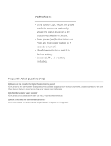
INSTALL DRIP TRAY
Your grill includes a sample drip tray liner. Place the liner
into the drip tray as shown in Fig. 17-2, and fully insert the
drip tray into the bottom front of the control panel.
Note: Be sure to center the liner in the drip tray, so that
it provides complete coverage under all of the
openings in the grill.

18
MENU
SET
®
078
080170
350
TEMP
SET ACT
°F
MEAT
OVEN
TIMER
00:00
Fig. 18-3 Default screen detail
Time set via Timer
Meat probe
temp. info
Oven temp.
info
MENU
SET
®
Fig. 18-2 Orientation
Arrows for
adjusting digits
SET button
for selecting &
confirming
Display screen
Timer
button
Menu
button
Power
button
Your electric grill comes with a digital thermometer/thermostat
for temperature control, oven and meat probe temperature
monitoring, and timed cooking. Pressing the power button
on the thermometer will turn on the grill. Once the grill is
turned on, the cooking element immediately begins to
heat. Preheating of the grill is required for it to reach
the desired cooking temperature. Set the desired
temperature as instructed below.
The thermometer will automatically shut off 2 hours from
the time the power button is pressed.
For optimal performance, keep the oven lid closed during
cooking. This will maintain the cooking temperature.
(Frequently opening or leaving the lid open during cooking
will result in greater temperature loss.)
The thermometer is located on the left side of the control
panel. The actual grill temperature will be maintained within
a 20 degree (Fahrenheit) differential of the set temperature.
Plug in the meat probe on the left side of the control panel
as shown in Fig. 18-1.
FOR BEST PERFORMANCE, GENTLY PRESS THE
BUTTONS. When turned on, accurate temperature readings
will begin after the thermometer has initialized. When turned
off, allow 5 seconds prior to turning back on.
Read the following sections completely regarding
thermometer/thermostat operation. Refer to Fig. 18-2 for
thermometer orientation and button locations.
Default Screen
Press the power button to turn the thermometer ON. The
default screen will be displayed. Temperatures for the oven
and meat probe will be shown (see Fig. 18-3).
Menu Screen
Press the power button to turn the thermometer ON. The
default screen will be displayed. Press the MENU button to
display its screen. Press the up/down arrow to scroll through
the options (see Fig. 18-4).
Note: The menu screen will return to the default screen
after approximately 30 seconds of no activity. Press
the MENU button to manually return to the default
screen.
MENU
SET
®
SETUP
GRILL GUIDE
ALARM
BACKLIGHT
Fig. 18-4 Menu screen
USE, CARE, & SERVICE
Fig. 18-1 Meat probe detail
MEAT PROBE
Meat probe
plug
Meat probe
handle
MEAT PROBE
Meat probe
plug
Meat probe
handle
DIGITAL THERMOMETER / THERMOSTAT

19
MENU
SET
®
OVEN
ACTUAL: 078
SET TEMP: 350
Fig. 19-1 Area temp. screen (oven shown)
Current location
Set this temp. as desired
Use arrows
to set
MENU
SET
MED
RARE
WELL
DONE
170
170
180
160
N/A
160
150
N/A
150
140
N/A
140
BEEF
PORK
LAMB
PROBE
TEMP
MEDRARE
®
Fig. 19-2 Grill Guide screen
Use arrows
to view
desired
meat
Fig. 19-3 Meat probe
Meat probe
Only check food
temperature with
hood open
DO NOT USE MEAT PROBE
WITH HOOD CLOSED
Setting Oven and/or Meat Probe Temperature
1. From the default screen, press the down arrow to the desired
oven / meat probe area (flashing). Press SET.
Note: The OVEN SET TEMP controls the temperature inside
of the grill. (This is the thermostat function.)
2. The selected location’s temperature screen will be displayed.
Use the arrows to set the desired temp. The actual temp.
will also be shown (see Fig. 19-1).
Note: PRESSING the arrows will adjust the desired temp.
by increments of one degree. HOLDING them down
(for several seconds) will adjust the temp. rapidly.
3. Press SET to return to the default screen. Repeat as
necessary for other area.
The display will flash red and the alarm will sound (if set to do
so) when the oven / meat probe reaches its set temperature.
Press any button to silence.
Grill Guide and Meat Probe
The grill guide displays recommended ready temperatures for
various meats (see Fig. 19-2).
1. Under the menu screen select GRILL GUIDE. Press SET.
2. Press the up/down arrow to view the desired meat.
3. Note the temp. and press SET. This will take you to the
meat probe temperature screen.
4. Use the arrows to set the noted temp.
5. Press SET to return to the default screen.
Inserting the meat probe into the cooking meat will give an
actual temp. reading. The display will flash red and the alarm
will sound (if set to do so) when the actual temp. reaches the
set temp. Press any button to silence.
Do not leave the meat probe in the meat for a prolonged
period of time, or with the hood closed. The meat probe
is calibrated specifically for use at temperatures between
130°F and 180°F.
Setting the Timer
1. Press the timer button. Use the arrows to set the desired
amount of time (see Fig. 19-4).
2. Press SET to return to the default screen.
The time remaining will be shown on the default screen. Once
the time reaches zero; the display will flash red and the alarm
will sound. Press any button to silence.
MENU
SET
05:00
TIMER
®
Fig. 19-4 Timer screen
Set time as desired
Use arrows
to set
Timer button
Meat probe
Only check food
temperature with
hood open
DO NOT USE MEAT PROBE
WITH HOOD CLOSED
DIGITAL THERMOMETER / THERMOSTAT (cont.)

20
Setting the Alarm (Oven Temp. or Meat Probe)
The alarm can be individually set (ON or OFF) for the meat
probe and oven temp. The default setting has the alarm OFF
for the meat probe and oven temp. The alarm always alerts
for the TIMER.
1. Under the menu screen select ALARM. Press SET.
2. Use the up/down arrow to select the desired alarm,
and press the power button to turn the alarm ON/OFF.
3. Press SET to return to the menu screen.
4. Press MENU to return to default screen.
Setting the Thermometer Backlight
The default color for the thermometer backlight is blue. The
color may be changed as desired by turning the three base
colors ON/OFF. Various combinations will result in different
colors.
1. Under the menu screen select BACKLIGHT. Press SET.
2. Use the up/down arrow to select the desired color, and
press the power button to turn the color ON/OFF.
3. Press SET to return to the menu screen. The new color
will now show.
4. Press MENU to return to default screen.
Note: Turning all colors OFF will result in no backlight.
Important: Turn on no more than 2 colors at a time.
Changing Temperature Scale (°C/°F)
1. Under the menu screen select SETUP. Press SET.
2. Press SET to select SETUP FC.
3. Select as desired and press SET to return to the menu
screen.
4. Press MENU to return to the default screen.
MENU
SET
®
OFF
ON
OVEN
PROBE
Fig. 20-1 Alarm screen
Press power button to
turn colors ON/OFF
Use arrows
to select
desired
alarm
MENU
SET
®
OFF
OFF
ON
BACKLIGHT
RED
GREEN
BLUE
Fig. 20-2 Backlight screen
Press power button
to turn ON/OFF
Use arrows
to select
desired
color
MENU
SET
®
TEMPERATURE
F
C
Fig. 20-3 Temperature scale screen
Select as
desired
DIGITAL THERMOMETER / THERMOSTAT (cont.)
/