American Standard 6065.121.002 Installation guide

Category
Sanitary ware
Type
Installation guide

This manual is also suitable for

American Standard 6065.121.002 is an exposed flushometer for 1-1/2" top spud bowls that provides both manual and automatic flushing options with its sensor-operated design, allowing for hands-free operation. This flushometer is also designed to be water-efficient, meeting the WaterSense certification standards for conserving water. Additionally, it complies with ASME A112.19.2 standards, ensuring its quality and performance.

American Standard 6065.121.002 is an exposed flushometer for 1-1/2" top spud bowls that provides both manual and automatic flushing options with its sensor-operated design, allowing for hands-free operation. This flushometer is also designed to be water-efficient, meeting the WaterSense certification standards for conserving water. Additionally, it complies with ASME A112.19.2 standards, ensuring its quality and performance.

1
M965646 REV. 2.1 (10/19)
© 2019 AS America Inc.
NOTE TO INSTALLER: Please give this manual to the customer after installation.
To learn more about American Standard Selectronic
®
Products visit our website at: www.americanstandard-us.com
or e-mail us at: CRTTEAM@americanstandard.com
For Parts, Service, Warranty or other Assistance,
please call (844) CRT-TEAM / (844) 278-8326 (In Canada: 1-800-387-0369)
(In Toronto Area only: 1-905-306-1093))
Ultima
Selectronic
®
Battery Powered
Toilet Flush Valve, Piston-Type
Installation Instructions
Certied to comply with ASME A112.19.2
© 2019 AS America, Inc.
CAUTION: Use only American Standard supplied
transformers and cable sets. Using non-AS supplied
cables, or cutting, splicing or modifying any components
will void the warranty.
Exposed Flushometer
for 1-1/2" Top Spud Bowls
MODEL NUMBERS
6065.111 6065.521
6065.121 6065.525
6065.161 6065.561
6065.721 6065.565
6065.761
Product to be used with WaterSense Certied
Fixture with the same rated ush volume.
2
M965646 REV. 1.7 (7/17)
Thank you for selecting American-Standard...the benchmark of ne quality for over 100 years. To ensure that your
installation proceeds smoothly--please read these instructions carefully before you begin.
Remove the Flush Valve items from the carton. The illustration below shows all items after they have been
removed from the carton. Some items may be packaged partially assembled to other items.
UNPACKING
All American Standard Products Are Water Tested At Our Factory.
Some Residual Water May Remain In The Valve During Shipping.
1. Installation Instructions
2. Flush Valve Body Assembly
3. Vacuum Breaker Tube
4. Spud Coupling Nut and Washers
5. Spud Flange
6. Wall Escutcheon
7. Cover Tube
8. Sweat Adapter
9. Stop Valve
CARE INSTRUCTIONS:
DO: CLEAN THE PRODUCT WITH CLEAR WATER. DRY WITH A SOFT COTTON FLANNEL CLOTH.
DO NOT: DO NOT CLEAN THE PRODUCT WITH SOAPS, ACID, POLISH, ABRASIVES, HARSH CLEANERS, OR A
CLOTH WITH A COARSE SURFACE.
2
1
3
4
5
8
6
9
DO NOT REMOVE PROTECTIVE FILM FROM SENSOR
EYE UNTIL INSTALLATION IS COMPLETE.
7
Installation Instructions
Certified to comply with ASME A112.19.2
© 2019 AS America, Inc.
Exposed Flushometer
for 1-1/2" Top Spud Bowls
CAUTION: Use only American Standard
supplied cable sets. Using non-AS supplied
cables, or cutting, splicing or modifying any
components will void the warranty.
6065.111
6065.121
6065.161
6065.721
6065.761
6066.565
6065.521
6065.525
6065.561
6065.565
6066.525
6066.561
MODEL NUMBERS
NOTE TO INSTALLER: Please give this manual to the customer after installation.NOTE TO INSTALLER: Please give this manual to the customer after installation.
To learn more about American Standard Selectronic
®
Products visit our website at: www.americanstandard-us.com
or e-mail us at: CRTTEAM@americanstandard.com
For Parts, Service, Warranty or other Assistance,
please call (844) CRT-TEAM / (844) 278-8326 (In Canada: 1-80 0-387-0369)
(In Toronto Area only: 1-905-306-1093)
Ultima
Selectronic
®
Toilet Flush Valve, Piston-Type
M965646 REV. 2.1 (10/19)
3
M965646 REV. 2.1 (10/19)
1. Installation Instructions
2. Flush Valve Body Assembly
3. Vacuum Breaker Tube
4. Spud Coupling Nut and Washers
5. Spud Flange
6. Wall Escutcheon
7. Cover Tube
8. Sweat Adapter
9. Stop Valve
GENERAL DESCRIPTION:
SELECTRONIC® PROXIMITY TOILET FLUSH VALVE
Exposed Flushometer for 1-1/2” Top Spud Fixtures
419 mm
(16-1/2")
292 mm
(11-1/2")
127 mm
(5")
73 mm
(2-7/8")
(NPT de 1")
15˚
170 mm MÁX.
(6-11/16") MÁX.
406 mm
(16")
292 mm
(11-1/2")
114 mm
(4-1/2")
73 mm
(2-7/8")
(NPT de 1")
15˚
170 mm MÁX.
(6-11/16") MÁX.
*Note: The Critical Line (-C-L-) on Vacuum
Breaker must typically be 6
" (152mm) above
fixture. Consult Codes for details.
-C-L-
SUPPLY
(1" NPT.)
FINISHED WALL
108mm-134mm
(4-1/4" TO 5-1/4")
FOR 1-1/2" TOP
SPUD FIXTURES
MANUAL
OVERRIDE
BUTTON
DETECTION ZONE
400mm-800mm
(15-3/4 TO 31-1/2)
*-C-L-
152mm MIN.
(6") MIN.
108mm-134mm
(4-1/4" TO 5-1/4")
FOR 1-1/2" TOP
SPUD FIXTURES
152mm MIN.
(6") MIN.
MANUAL
OVERRIDE
BUTTON
Fig. 1 (Before November 2017)
Roughing-in Dimensions
Right or Left Hand Installation
See (Section 5) for converting Flush Valve to Left Hand Installation.
Fig. 1A (After November 2017)
FINISHED WALL
ø51 mm
(ø2") GRAB BAR (Max.)
FINISHED
FLOOR
406 mm
(16")
914 mm
(36")
GRAB BAR
HEIGHT
38 mm
(1-1/2")
419 mm
(16-1/2")
TO RIM
ADA WATER CLOSET INSTALLATION:
AFWALL
®
TOILET SHOWN
293 mm
(11-1/2")
-C-L-
4
M965646 REV. 2.1 (10/19)
RECOMMENDED TOOLS; Fig. 2.
1. Teon Tape
2. Flat Blade Screwdriver
3. Adjustable Wrench
4. Tape Measure
5. Hacksaw
6. Tubing Cutter
7. File
8. For Sweat Connection; Solder and Torch
9. 2.5 mm Hex Wrench
10. 1.5 mm Hex Wrench
PRIOR TO INSTALLATION
Note: Prior to installing the Selectronic™Flush
Valve the following items must be installed.
1. Toilet
2. Drain line
3. Water supply line
IMPORTANT:
All plumbing and electrical wiring should be
installed in accordance with applicable codes
and regulations.
The use of water hammer arrestors is strongly
recommended for commercial applications. All piping
behind the walls should be properly secured and
fastened.
Water supply lines must be sized to provide an
adequate volume of water for each xture.
Flush all water lines prior to operation. Dirt and debris
can cause ush valve to run continuously.
With the exception of Stop Valve Inlet, DO NOT
use pipe sealant or plumbing grease on any
valve component or coupling!
Protect the chrome or special nish on the Flushometer.
DO NOT USE toothed tools on nished surfaces to install
or service these valves. Also see “Care and Cleaning”
section of this manual.
This product contains mechanical and/or electrical
components that are subject to normal wear. These
components should be checked on a regular basis and
replaced as needed to maintain the valves performance.
Fig. 2
1
2
3
4
5
6
7 9 10
8
10'
5
M965646 REV. 2.1 (10/19)
CENTER LINE OF
FIXTURE SPUD
FINISHED WALL
FILE EDGES
SOLDER
ADAPTER
Fig. 3
ADAPTER
32mm
(1-1/4")
A
(A-B)=
B
C
CLEAN
Fig. 4a
Fig. 4b
Fig. 4c
1
1
4
2
3
Fig. 4
TEFLON TAPE
FINISHED WALL
X
X
2
1
2
3
4
5
Fig. 5
1-1/2" TOP SPUD
FLUSH VALVE INSTALLATION
1
INSTALL SWEAT ADAPTER; Fig. 3
Note: Install Optional Sweat Adapter (Supplied) for
copper pipe supply line.
1. Measure the distance (A) from the nished wall to the
center of the inlet spud on the xture.
2. Cut the supply pipe 1-1/4" (A-B=C) shorter than the
measurement taken in Step 1. File any rough edges
off the end of the supply pipe.
3. Clean the end of the supply pipe. Push the threaded
Adapter until it is seated against the internal stop.
Sweat the Adapter to the pipe.
2
INSTALL COVER TUBE, WALL
ESCUTCHEON and STOP VALVE;
Fig. 4
1. Measure from nished wall to rst thread of Adapter or
threaded supply pipe (dimension “X”). Cut COVER TUBE
(1) to length (X). Apply Teon Tape to the threaded end of
the Adapter or supply pipe.
2. Push WALL ESCUTCHEON (2) onto the COVER TUBE (1).
Slide both onto the SUPPLY PIPE (3).
3. Push the COVER TUBE (1) in to expose the threads of
the supply pipe. With a wrench thread the STOP VALVE
(4) onto the SUPPLY PIPE (3). Align and tighten.
4. Pull COVER TUBE (1) against STOP VALVE (4) and push
WALL ESCUTCHEON (2) against nished wall.
3
INSTALL VACUUM BREAKER
TUBE; Fig. 5
1. Place the SPUD FLANGE (1) over the spud on
the Fixture.
2. Place FRICTION WASHER (3) and SEAL WASHER
(4) inside SPUD COUPLING NUT (2) and thread
onto Spud. Do not tighten fully.
3. Insert the VACUUM BREAKER TUBE (5) into the
SPUD COUPLING NUT (2) and push it down.
Note: If cutting VACUUM BREAKER TUBE (5) to size, note
that Critical Line (C/L) on Vacuum Breaker must typically
be 6” (152mm) above xture. Consult Code for details.
CAUTION
Turn water supplies off before
beginning
6
M965646 REV. 2.1 (10/19)
4
FLUSH OUT SUPPLY LINES; Fig. 6
1. Remove STOP VALVE COVER (1) from STOP VALVE (2).
2. Open STOP VALVE (2) with a at blade screwdriver.
3. Turn on water supply to ush line of any debris or sediment.
4. Close STOP VALVE (2) and replace STOP VALVE COVER (1).
5
LEFT OR RIGHT HAND
INSTALLATION; Fig. 7
The unit is shipped with adjustable tailpiece on the
right side. If needed, the orientation can be modied
by following the steps below.
1. Loosen SET SCREW (1) with 2.5mm Hex Wrench (4)
in back of FLUSH VALVE COVER (2).
2. Rotate FLUSH VALVE COVER (2) to the right and pull off.
3. Rotate FLUSH VALVE BODY (3) 180˚.
4. Replace COVER (2) and rotate until key engages.
Tighten SET SCREW (1).
6
INSTALL FLUSH VALVE; Fig. 8, 8a
1. Insert ADJUSTABLE TAILPIECE (1) into the STOP
VALVE (2). Lubricate the O-RING (3) with water if
necessary. Lightly tighten COUPLING NUT (4). Fig. 8.
Important: Do not use lubricants (other than water) or
any type of thread sealing paste or tape
2. Align the FLUSH VALVE BODY (5) directly above the
VACUUM BREAKER TUBE (7) and VACUUM BREAKER
COUPLING NUT (6). Fig. 8a.
Note: There is a +13mm, -6mm (+1/2, -1/4) tolerance for
the 121mm (4-3/4) dimension. Fig. 8a.
3. Pull the VACUUM BREAKER TUBE (7) up to meet the
threaded FLUSH VALVE BODY (5), hand tighten the
VACUUM BREAKER COUPLING NUT (6). Align all
components of the ush valve assembly. Fig. 8a.
4. Lightly tighten the COUPLING NUT (4) connection rst,
then the VACUUM BREAKER COUPLING NUT (6) and
nally the SPUD COUPLING NUT (8). Once alligned
correctly, use a wrench to tighten couplings to make
water tight connections. Fig. 8a.
1
CLOCKWISE CLOSES
STOP VALVE
COUNTER-CLOCKWISE
OPENS STOP VALVE
REMOVE COVER
Fig. 6
2
2
4
Fig. 7
4
KEY
2
2
1
3
180˚
2
1
7
8
6
5
4
121mm,+13mm, -6mm
(4-3/4)(+1/2, -1/4)
Fig. 8 Fig. 8a
2
4
1
3
7
M965646 REV. 2.1 (10/19)
A
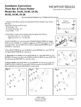
ADJUST STOP VALVE; Fig. 9
IMPORTANT: To avoid overowing, the STOP VALVE (3)
must never be opened to the point where the ow from
the valve exceeds the ow capacity of the xture.
1. After installation is complete, peel off the PROTECTIVE
FILM (1) from the sensor. Standing to one side, block the
sensor with your hand for 10 seconds. Remove your hand
and listen for audible “click” from within the valve.
2. Remove STOP VALVE COVER (2) from STOP VALVE (3).
Turn on water supply 1/4 turn to 1/2 turn(CCW) and test
for leaks.
Note: Unit may ush for approximately 5 to 10 sec.
when water is rst turned on. If ow persists, turn
water off and repeat step #1 above.
3. Actuate the FLUSH VALVE:
A) Cover sensor with hand for 10 seconds.
NOTE: Stand outside of sensor detection area.
B) Remove hand from in front of the sensor; unit will ush
in approximately 3 seconds.
4. Adjust STOP VALVE (3) after each ush until the stated
ush volume is achieved, no splashing occurs and the
xture is properly cleansed.
5. When adjustment is complete, replace STOP VALVE
COVER (2) and tighten to ensure vandal-resistance.
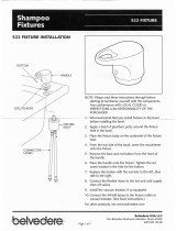
B
RETROFITING WITH SELECTRONIC
VALVE; Fig. 10
(Replaces Industry Standard Manual and
Electronic Valves)
Note: In most Retrots the wall escutcheon, stop valve,
cover tube and vacuum breaker do not have to be
replaced. If these items do need replacement they must
be purchased separately or order the complete ush
valve assembly from American Standard.
1. Remove STOP VALVE COVER (1) from STOP VALVE (2).
2. Turn water supply off.
3. Loosen SPUD COUPLING NUT (3). Unthread COUPLING
NUT (4) and VACUUM BREAKER COUPLING NUT (5).
Remove FLUSH VALVE (6).
4. Clean all threaded connections before installing the new
ush valve.
5. Refer to Sections 4, 5 and 6 to complete the retrot
installation.
1
Fig. 9
2
REMOVE COVER
CLOCKWISE CLOSES
STOP VALVE
COUNTER-CLOCKWISE
OPENS STOP VALVE
3
MAINTENANCE
CLEAN
CONNECTIONS
2
Fig. 10
1
4
5
3
6
8
M965646 REV. 2.1 (10/19)
C
REPLACE BATTERY; Fig. 11, 11a
1. Loosen SET SCREW (1) with 2.5mm Hex Wrench (2) in
back of FLUSH VALVE COVER (3). Fig. 11.
2. Rotate COVER (3) to the right and pull off. Fig. 11.
3. Turn COVER (3) over and disconnect the SENSOR (4)
from the BATTERY HOLDER (5). Remove the BATTERY
CONTAINER (6) with BATTERY HOLDER (5) and
BATTERY (7) inside. Fig. 11a.
4. Remove BATTERY HOLDER (5) from BATTERY
CONTAINER (6). Fig. 11a.
5. Remove old BATTERY from BATTERY HOLDER (5).
Install the new BATTERY (7) making sure the shape
of the BATTERY follows the shape of the BATTERY
HOLDER (5). Fig. 11a.
6. Insert BATTERY HOLDER (5) with BATTERY into
BATTERY CONTAINER (6). Instert BATTERY
CONTAINER (6) into ush valve COVER (3). Fig. 11a.
7. Connect BATTERY HOLDER (5) to SENSOR (4) and
reverse the above steps to assemble ush valve. Fig. 11a.
3
3
4
8
3
1
Fig. 11
Fig. 11a
Fig. 11b
REMOVE OLD
BATTERY
REMOVE
BATTERY
HOLDER
INSTALL
NEW
BATTERY
2
5
4
5
CR-P2
CR-P2
5
7
6
6
REMOVE OLD
LONG LIFE
POWER PACK
LONG LIFE POWER PACK
STANDARD BATTERY
INSTALL NEW
LONG LIFE
POWER PACK
8
9
M965646 REV. 2.1 (10/19)
3
Fig. 13
VIEW “A
1
2
5
3
6
VIEW “A
4
STANDARD BATTERY
D
SET DETECTION RANGE
(If Required); Fig. 13 y 14
Note: The detection distance is preset and ideal for most
installations. Should an adjustment be required, follow
the steps below.
1. Loosen SET SCREW (1) with 2.5mm Hex Wrench (2) in
back of FLUSH VALVE COVER (3). Fig. 13a.
2. Rotate COVER (3) to the right and pull off. Fig. 13b.
3. Turn COVER (3) over and disconnect CABLE (4) from
BATTERY HOLDER (5). Fig. 13.
4. Keeping hands away from the sensor detection area,
reconnect the SENSOR (4) and quickly place the COVER
(3) on the valve. Do not secure the COVER (3) at this time.
Note: You have 5 seconds to begin entering the program
code after power connection is made.
5. While the SENSOR CONTROL LED (1) is blinking slowly,
place your hand 1 to 2 in. (30-50mm.) in front of the sensor.
Fig. 14.
6. When the LED (1) stops blinking and stays “ON”, move your
hand to the desired position and hold in place until the LED
(1) begins to blink again. Fig. 14.
Note: Detection Zone is 400mm - 800mm.
(Factory Setting: 400mm)
7. Once the SENSOR CONTROL LED (1) begins to blink
again, remove your hand from the detection zone.
When the ashing stops, the detection distance is set.
8. Replace and secure COVER (3) onto valve.
9. Actuate the FLUSH VALVE:
A) Cover sensor with hand for 10 seconds.
NOTE: Stand outside of sensor detection area.
B) Remove hand from in front of the sensor; unit will
ush in approximately 3 seconds.
1
1
1" - 2" (30mm - 50mm
BLINKING LED
BLINKING LED
Fig. 14
DETECTION ZONE
400mm TO 800mm
(Factory Setting: 400mm)
10
TROUBLESHOOTING FLOW CHARTS
NNOO
YYEESS
NNOO
YYEESS
NNOO
11
22
11
22
YYEESS
NNOO
YYEESS
NNOO
UNIT DOES NOT FUNCTION
NNOO
NNOO
11
22
11
22
YYEESS
NNOO
NNOO
YYEESS
UNIT WILL ONLY FLUSH MANUALLY
YYEESS
NNOO
NNOO
11
22
11
22
NNOO
YYEESS
UNIT IS CONTINUOUSLY FLUSHING
OPEN VALVE
CRITICALLY LOW BATTERY . INSTALL
NEW BATTERY
DEAD BATTERY. INSTALL NEW
BATTERY. REPEAT.
DAMAGED SENSOR WIRE. REPLACE
SENSOR. (ONLY IF ABSOLUTELY NEEDED)
DAMAGED SOLENOID. REPLACE
SOLENOID
DAMAGED MANUAL OVERRIDE
BUTTON. REPLACE MANUAL
OVERRIDE BUTTON
DEAD BATTERY. INSTALL NEW
BATTERY. REPEAT.
DAMAGED SENSOR WIRES. REPLACE
SENSOR. (ONLY IF ABSOLUTELY NEEDED)
DAMAGED SENSOR WIRES. REPLACE
SENSOR. (ONLY IF ABSOLUTELY NEEDED)
CRITICALLY LOW BATETRY. INSTALL
NEW BATTERY
IS ANGLE STOP OPEN?
REPEATED DOUBLE
FLASH ON SENSOR?
RECONNECT BATTERY TO SENSOR.
FLASH ON SENSOR FOR 5
SECONDS?
PUSH MANUAL OVERRIDE
BUTTON; WILL THE UNIT FLUSH?
REPLACE PISTON ASSEMBLY.
CLOSE ANGLE STOP AND OPEN
AGAIN TO PRIME THE VALVE.
DOES FLUSHING STOP?
PUSH MANUAL OVERRIDE
BUTTON. DOES IT RETURN TO ITS
ORIGINAL POSITION FREELY?
RECONNECT BATTERY TO SENSOR.
FLASH ON SENSOR FOR 5
SECONDS?
REPLACE PISTON & SOLENOID
ASSEMBLY.
REPEATED DOUBLE
FLASH ON SENSOR?
RECONNECT BATTERY TO SENSOR.
FLASH ON SENSOR FOR 5
SECONDS?
REPLACE SOLENOID
.
DEAD BATTERY. INSTALL NEW
BATTERY. REPEAT.
HOT LINE FOR HELP
For toll-free information and answers to your questions, call:
(844) CRT-TEAM / (844) 278-8326
IN CANADA 1-800-387-0369 (TORONTO 1-905-306-1093)
Weekdays 8:00 a.m. to 7:00 p.m. EST
IN MEXICO 01-800-839-1200
Product names listed herein are trademarks of AS America, Inc. © 2019
To learn more about American Standard Selectronic® Products visit our website at:
www.americanstandard-us.com or e-mail us at: [email protected]
Mon. - Fri. 8:00 a.m. to 8:00 p.m. EST Saturday 10:00 a.m. to 4:00 p.m. EST
M965646 REV. 2.1 (10/19)
11
M950319-0071600A
SENSOR ASSEMBLY (1.6 gpf)
M950319-0071280A
SENSOR ASSEMBLY (1.28 gpf)
M950319-0071100A
SENSOR ASSEMBLY (1.1 gpf)
M950319-0074000A
SENSOR ASSEMBLY
(1.6/1.1 gpf)
M950319-0075000A
SENSOR ASSEMBLY
(1.28/1.1 gpf)
M964411-0020A
1-1/2" VACUUM BREAKER
M950354-0020A
MANUAL VALVE
M964402-0070A
VACUUM BREAKER KIT
A955056-0020A
1" STOP VALVE KIT
M964945-0020A
ADJUSTABLE TAILPIECE
(4-1/4" to 5-1/4" Rough-in)
OPTIONAL ADJUSTABLE TAILPIECE
(Purchased Separately)
M962836-0020A (8-1/4" to 9-1/4" Rough-in)
M962835-0020A (7-1/4" to 8-1/4" Rough-in)
M962834-0020A (6-1/4" to 7-1/4" Rough-in)
M962833-0020A (5-1/4" to 6-1/4" Rough-in)
A955057-0020A
1" INLET PIPE ASSEMBLY
M950514-0070A
BATTERY HOLDER
A923654-0070A
BATTERY 6V CR-P2
CR-P2
Standard Battery
6065 Series
Power Source
M906684-0070A
BONNET NUT
A917376-0070A
SET SCREW
M964942-0021600A
COVER ASSEMBLY (1.6 gpf)
M964942-0021280A
COVER ASSEMBLY (1.28 gpf)
M964942-0024000A
COVER ASSEMBLY (1.6/1.1 gpf)
M964942-0023000A
COVER ASSEMBLY (1.28/1.1 gpf)
M964942-0021100A
COVER ASSEMBLY (1.1 gpf)
M964551-0070A
PISTON ASSEMBLY
M964302-0070A
SOLENOID ASSEMBLY
M964852-0070A
SOLENOID & PISTON
SUB ASSEMBLY
Standard Battery (6065 Series)
BEFORE NOVEMBER 2017 AFTER NOVEMBER 2017
A912809-0070A
O-RING
M962926-0070A
1" SWEAT ADAPTER
M952269-0020A
ESCUTCHEON KIT
M924347-0020A
STOP VALVE CAP
M906684-0070A
BONNET NUT
A917376-0070A
SET SCREW
M970343-0021600A
COVER ASSEMBLY (1.6 gpf)
M970343-0021280A
COVER ASSEMBLY (1.28 gpf)
M970343-0024000A
COVER ASSEMBLY (1.6/1.1 gpf)
M970343-0023000A
COVER ASSEMBLY (1.28/1.1 gpf)
M970343-0021100A
COVER ASSEMBLY (1.1 gpf)
M964551-0070A
PISTON ASSEMBLY
M964302-0070A
SOLENOID ASSEMBLY
M964852-0070A
SOLENOID & PISTON
SUB ASSEMBLY
Standard Battery (6065 Series)
Ultima
Selectronic
®
Battery Powered
Toilet Flush Valve, Piston-Type
M965646 REV. 2.1 (10/19)
HOT LINE FOR HELP
For toll-free information and answers to your questions, call:
(844) CRT-TEAM / (844) 278-8326
IN CANADA 1-800-387-0369 (TORONTO 1-905-306-1093)
Weekdays 8:00 a.m. to 7:00 p.m. EST
IN MEXICO 01-800-839-1200
Product names listed herein are trademarks of AS America, Inc. © 2019
To learn more about American Standard Selectronic® Products visit our website at:
www.americanstandard-us.com or e-mail us at: CR[email protected]
Mon. - Fri. 8:00 a.m. to 8:00 p.m. EST Saturday 10:00 a.m. to 4:00 p.m. EST
MODEL NUMBERS
6065.111 6065.521
6065121 6065.525
6065.161 6065.561
6065.721 6065.565
6065.761
  • Page 1 1
  • Page 2 2
  • Page 3 3
  • Page 4 4
  • Page 5 5
  • Page 6 6
  • Page 7 7
  • Page 8 8
  • Page 9 9
  • Page 10 10
  • Page 11 11

American Standard 6065.121.002 Installation guide

Category
Sanitary ware
Type
Installation guide
This manual is also suitable for

American Standard 6065.121.002 is an exposed flushometer for 1-1/2" top spud bowls that provides both manual and automatic flushing options with its sensor-operated design, allowing for hands-free operation. This flushometer is also designed to be water-efficient, meeting the WaterSense certification standards for conserving water. Additionally, it complies with ASME A112.19.2 standards, ensuring its quality and performance.

Ask a question and I''ll find the answer in the document

Finding information in a document is now easier with AI