Page is loading ...

®
N8583V1 5/98
INSTALLATION INSTRUCTIONS
5809
RATE-OF-RISE HEAT DETECTOR/TRANSMITTER
For use with QED control panels ONLY!
GENERAL INFORMATION
The Ademco 5809 Rate-of-Rise Heat Detector/Transmitter is
intended for use with wireless alarm systems that support QED
5800 series devices, and contains a built-in transmitter which
can send alarm, supervisory and battery condition messages to
the system's receiver/control unit. Refer to the QED wireless
system's instructions for the maximum number of transmitters
that can be supported.
The 5809 combines both rate-of-rise and fixed temperature
sensors. Fires typically cause a rapid rise in temperature in the
surrounding area. The 5809’s rate-of-rise thermostat senses the
rise in temperature and signals an alarm if the rise is 15°F (8°C)
or more per minute. A built-in fixed temperature sensor will
also signal an alarm if the ambient temperature rises above
135°F (57°C).
NOTE: If the fixed temperature sensor activates, the
5809 must be replaced.
The 5809 is powered by a 3-volt lithium battery. If the battery
voltage gets too low, the 5809 sends a low battery signal to the
control panel.
The 5809 also features a tamper switch, which causes a trouble
signal to be sent to the control if the unit is removed from the
mounting base.
A built-in activation button, located on the PC board assembly,
is used when programming the unit’s serial number at the
control and when testing the unit.
INSTALLING THE BATTERY
Important Notes:
• Use 3-volt lithium battery:
Duracell DL123A or
Panasonic/Sanyo/Varta CR123A.
• Observe polarity.
• When replacing the battery, wait at least 30 seconds after
removing the old battery, before installing the new one.
Remove the detector from its base and install a 3-volt lithium
battery as shown below.
+
BATTERY
PROGRAMMING THE UNIT
The transmitter’s serial number must be enrolled in the QED
control panel before usage in the system. The QED control unit's
installation instructions provide detailed programming
procedures for enrolling transmitter serial numbers. Before
programming, do the following:
1. Remove the unit assembly from its mounting base by
twisting counter-clockwise and lifting.
2. Install the battery (if not already installed). Observe polarity!
3. Enter the control’s programming mode and follow the
control’s programming instructions. When programming
this transmitter at the control, note the following:
• Input Type = 3 (Supervised RF)
• Loop Number = 1
Transmit from the detector when prompted (momentarily
press the activation button located on the exposed
transmitter PC board, install battery, etc.). You can also
manually enter the detector’s serial number.
4. Test the detector after enrolling into the system. Refer to the
Testing section.
ACTIVATION
BUTTON
BATTERY
••
•
•
MOUNTING THE DETECTOR
You can mount the 5809 on a wall or ceiling within the
protection area:
• Wall Mounting: Mount the detector 4”-6” from the ceiling.
• Ceiling Mounting: Mount the detector at least 4” from any
wall. Make sure the normal ceiling temperature will not
exceed 100°F.
• Refer to NFPA Standard 72 for detector spacing and other
requirements. Maximum spacing for UL installations is
50’x50’.
• Avoid mounting the detector near heat generating devices
(e.g. ovens, heat vents, furnaces, boilers).
IMPORTANT:
Heat detectors should be used for
property protection. Reliance should
not be placed solely on heat detectors
for life safety.
When life safety is
involved, smoke detectors MUST
also be used. Detectors must not be
painted.
Previous Menu

Wireless Transmission Path Test
A good RF transmission path must be established from the
proposed mounting location before permanently installing the
detector. To determine that there is good signal reception from
the proposed location, perform the test procedure described in
the TESTING THE DETECTOR section.
Once a good RF transmission path is confirmed, mount the
detector as follows:
1. Surface mount the unit’s plastic base to a wall or ceiling, or
mount the plastic base to either a 4” junction box or 3-1/4”
octagon box.
2. Mount the detector PC board assembly to the base and
secure by twisting clockwise. Make sure to align the
tamper contact wire on the base with the electrical pads
on the underside of the PC board assembly when
installing to the base.
WALL OR CEILING
MOUNTING HOLES
(USE EITHER A or B LOCATIONS)
PC ASSEMBLY
MOUNTS
TAMPER
CONTACTS
(A)
(A)
(B)
(B)
TESTING THE DETECTOR
The test procedure should be performed to determine a good RF
transmission path and again after installation is completed.
CAUTION:
The rate-of-rise heat sensor is intended for
one-time use.
Prolonged heat during
testing can damage the unit.
If used
carefully following the instructions described
below, the heat from a portable hair dryer
can be used to test the unit. If the round
disk on top of the detector detaches, the
detector must be replaced.
1. Activate the control panel’s test mode.
2. Use either method (a) or (b) to activate the detector:
(a) Press and release the activation button on the PC
board assembly.
OR
(b) Holding a portable hair dryer about 12 to 18 inches
away from the detector, turn the dryer on and aim the
warm air at the side of the detector.
CAUTION: Aiming the dryer directly at the round
disk on the detector can damage the
detector requiring the unit to be
replaced.
3. The system’s keypads should beep and the detector’s ID
should be displayed.
4. Exit the control’s test mode.
¬19Jl
N8583V1 5/98
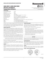
MAINTAINING PROPER OPERATION
To maintain the detector in proper working condition, it is im-
portant that you observe the following:
1. Replace the battery when the system indicates that the 5809
has reported a low battery condition.
2. Units should never be relocated without the advice or
assistance of the alarm service company.
SPECIFICATIONS
Power: 3V lithium battery
(Duracell DL123A, Panasonic
CR123A, Sanyo CR123A, Varta
CR123A)
CAUTION:
Risk of fire, explosion, and burns. Do not
recharge, disassemble, heat above 212° F
(100° C) or incinerate. Dispose of used
batteries promptly. Keep away from children.
Operating Temperature: 40° to 140°F (6° to 60°C)
Rate-of Rise Temperature: 15°F (8°C) increase per minute
(NOTE: Rate of rise sensor does
not operate above 38°C)
Fixed Temperature: 135°F (57°C)
Maximum Spacing: 50ft x 50ft UL
30ft x 30ft FM
(refer to National Fire Alarm Code
Standard NFPA 72 for application
requirements)
Dimensions: 4.4” diameter/ 2/2” deep
TO THE INSTALLER
The rate-of-rise mechanism may be subject to reduce sensitivity over
time. Annual testing of the rate-of rise operation is recommended.
Regular maintenance and inspection (at least annually) by the installer
and frequent testing by the user are vital to continuous satisfactory
operation of any alarm system.
The installer should assume the responsibility of developing and
offering a regular maintenance program to the user as well as
acquainting the user with the proper operation and limitations of the
alarm system and its component parts. Recommendations must be
included for a specific program of frequent testing (at least weekly) to
ensure the system's proper operation at all times.
FCC NOTICE
FCC ID: CFS 8DL 5809
This device complies with Part 15 of FCC rules. Operation is subject to
the following two conditions: (1) This device may not cause harmful
interference, and (2) this device must accept any interference received,
including interference that may cause undesired operation.
REFER TO THE INSTALLATION INSTRUCTIONS FOR THE
QED RECEIVER/CONTROL WITH WHICH THIS DEVICE IS
USED FOR DETAILS REGARDING LIMITATIONS OF THE
ENTIRE ALARM SYSTEM.
165 Eileen Way, Syosset, New York 11791
Copyright © 1998 PITTWAY CORPORATION
/