Page is loading ...

WARNING: If the information in these instructions
is not followed exactly, a fire or explosion may
result, causing property damage, personal injury
or loss of life.
♦ Do not store or use gasoline or other flammable
vapors and liquids in the vicinity of this or any
other appliance.
WHAT TO DO IF YOU SMELL GAS:
♦ Do not try to light any appliance.
♦ Do not touch electrical switches; do not use the
phone in your building.
♦ Immediately call your gas supplier from a
neighbor’s phone. Follow your gas supplier’s
instructions.
♦ If you cannot reach your gas supplier, call the fire
department.
Installation & service must be performed by a qualified
installer, service agency, or the gas supplier.
MODEL: #56101
‘
WINDOM’
DIRECT VENT GAS FIREPLACE
INSTALLATION AND
OPERATING MANUAL
This appliance may be installed in an aftermarket
permanently located, manufactured (mobile) home,
where not prohibited by local codes. This appliance is
only for use with the type(s) of gas indicated on the
rating plate. This appliance is not convertible for use
with other gases, unless a certified kit is used.
US Patent Number 5,931,154
US Patent Number 6,004,493
IMPORTANT:
READ INSTRUCTIONS CAREFULLY BEFORE INSTALLATION. FAILURE
TO INSTALL THIS FIREPLACE CORRECTLY CAN CAUSE SERIOUS
STRUCTURAL AND FIRE HAZARDS AND MAY VOID YOUR WARRANTY.
US
C
Beaverton
Oregon USA
OMNI-Test Laboratories, Inc.
Tested &
Listed By
www.kozyheat.com
March 2008

COMMONWEALTH OF MASSACHUSETTS
NOTE: The following requirements reference various Massachusetts and national codes not contained in this document.
REQUIREMENTS FOR THE COMMONWEALTH OF MASSACHUSETTS
For all side wall horizontally vented gas fueled equipment installed in every dwelling, building or structure used in whole or in part for
residential purposes, including those owned or operated by the Commonwealth and where the side wall exhaust vent termination is less than
seven (7) feet above finished grade in the area of the venting, including but not limited to decks and porches, the following requirements shall
be satisfied:
INSTALLATION OF CARBON MONOXIDE DETECTORS
At the time of installation of the side wall horizontal vented gas fueled equipment, the installing plumber or gas fitter shall observe that a hard
wired carbon monoxide detector with an alarm and battery bak-up is installed on the floor where the gas equipment is to be installed. In
addition, the installing plumber or gas fitter shall observe that a battery operated or hard wired carbon monoxide detector with an alarm is
installed on each additional level of the dwelling, building or structure served by the side wall horizontally vented gas fueled equipment. It
shall be the responsibility of the property owner to secure the services of qualified licensed professionals for the installation of hard wired
carbon monoxide detectors.
In the event that the side wall horizontally vented gas fueled equipment is installed a crawl space or an attic, the hard wired carbon monoxide
detector with alarm and battery back-up may be installed on the next adjacent floor level.
In the event that the requirements of the subdivision can not be met at the time of installation, the owner shall have a period of thirty (30)
days to comply with the above requirements; provided, however, that during said thirty (30) day period, a battery operated carbon monoxide
detector with an alarm shall be installed.
APPROVED CARBON MONOXIDE DETECTORS
Each carbon monoxide detector as required in accordance with the above provisions shall comply with NFPA 720 and be ANSI/UL 2034
listed and IAS certified.
SIGNAGE
A metal or plastic identification plate shall be permanently mounted to the exterior of the building at a minimum height of eight (8) feet above
grade directly in line with the exhaust vent terminal for the horizontally vented gas fueled heating appliance or equipment. The sign shall
read, in print size no less than (½) inch in size, “GAS VENT DIRECTLY BELOW. KEEP CLEAR OF ALL OBSTRUCTIONS”.
INSPECTION
The state of local gas inspector of the side wall horizontally vented gas fueled equipment shall not approve the installation unless, upon
inspection, the inspector observes carbon
monoxide detectors and signage installed in accordance with the provisions of 248 CMR 5.08 (2) (a) 1 through 4.
EXEMPTIONS
The following equipment is exempt from 248 CMR 5.08 (2) (a) 1 through 4.
• The equipment listed in Chapter 10 entitled “Equipment Not Required To Be Vented” in the most current edition of NFPA 54 as adopted
by the Board; and
• Product Approved side wall horizontally vented gas fueled equipment installed in a room or structure separated from the dwelling,
building or structure used in whole or in part for residential purposes.
MANUFACTURER REQUIREMENTS
GAS EQUIPMENT VENTING SYSTEM PROVIDED
When the manufacturer of Product Approved side wall horizontally vented gas equipment provides a venting system design or venting
system components with the equipment, the instructions provided by the manufacturer for installation of the equipment and the venting
system shall include:
• Detailed instructions for the installation of the venting system design or the venting system components; and
• A complete parts list for the venting system design or venting system.
GAS EQUIPMENT VENTING NOT
PROVIDED
When the manufacturer of Product Approved side wall horizontally vented gas equipment provides a venting system design or venting
system components with the equipment, the instructions provided by the manufacturer for installation of the equipment and the venting
system shall include:
• The referenced “special venting system” instructions shall be included with the appliance or equipment installation instructions; and
• The “special venting systems” shall be Product Approved by the Board, and the instructions for that system shall include a parts list and
detailed installation instructions.
A copy of all installation instructions for all Product Approved side wall horizontally vented gas fueled equipment, all venting instructions, all
parts lists for venting instructions, and/or all venting design instructions shall remain with the appliance or equipment at the completion of the
installation.
• Installation and repair must be done by a plumber or gas fitter licensed in the Commonwealth of Massachusetts.
• The flexible gas line connector used shall not exceed 36 inches (92 centimeters) in length.
• The individual manual shut-off must be a T-handle type.

INDEX
DESCRIPTION PAGE
SAFETY REQUIREMENTS / SPECIFICATIONS ……….. ................................................................. 2-3
MINIMUM CLEARANCES …………………………………. .................................................................... 3
TYPICAL INSTALLATION OPTIONS …………………………………. ............................................... 3-4
VENTING REQUIREMENTS …………………………………. ............................................................. 5-8
MINIMUM / MAXIMUM VENTING REQUIREMENTS…………. ............ 5-6
HORIZONTAL VENTING …………………………………. ......................... 7
VERTICAL VENTING …………………………………. ............................... 8
POSITION THE UNIT …………………………………. ...................................................................... 9-10
VENT SYSTEM FRAMING …………………………………. ....................... 9
ROUGH-IN DIMENSIONS …………………………………. ...................... 10
REMOVE THE GLASS ASSEMBLY …………………………………. .................................................. 11
DIRECT VENT CHIMNEY INSTALLATION …………………………………. ....................................... 11
FAN INSTALLATION …………………………………. .................................................................... 12-13
GAS LINE SPECIFICATIONS …………………………………. ....................................................... 14-15
SECURE THE MILLIVOLT BOARD …………………………………. ................................................... 15
LOG INSTALLATION …………………………………. ......................................................................... 16
THERMOSTAT - WALL SWITCH - REMOTE CONTROL INSTALLATION …………………………. . 17
COMPLETE THE INSTALLATION …………………………………. ..................................................... 18
LIGHTING & SHUTDOWN …………………………………. ............................................................ 19-20
MANIFOLD & INCOMING PRESSURE CHECK PROCEDURES …………………………………. ..... 21
CLEANING & MAINTENANCE REQUIREMENTS …………………………………. ............................ 22
MILLIVOLT BOARD REMOVAL / INSTALLATION …………………………………. ...................... 23-24
TROUBLE SHOOTING …………………………………. .................................................................. 25-26
REPLACEMENT PARTS LISTS ………………………………….......................................................... 27
WARRANTY POLICY …………………………………. .................................................................... 28-29
Page 1

IMPORTANT:
READ THIS MANUAL BEFORE INSTALLING AND USING THIS FIREPLACE
MODEL #56101 ‘WINDOM’ DIRECT VENT GAS FIREPLACE
This fireplace has been tested to and complies with ANSI Z21.88a-2007
V CSA 2.33a-2007 “VENTED GAS
FIREPLACE HEATERS” by OMNI-Test Laboratories, Beaverton, OR. Installation must conform with local
building codes or in the absence of local building codes, with the National Fuel Gas Code, ANSI Z223.1, NFPA
54 - Current Edition.
S
PECIFICATIONS
Height (front): . . . . . . . 32"
Height (back): . . . . . . . . 30 1/8"
Front width: . . . . . . . . . . 36"
Back width: . . . . . . . . . . 23 3/8"
Depth: . . . . . . . . . . . . . . 11"
Flue size: 4" exhaust
,
6
5/8
" combustion air intake
PASS-THRU WALL THICKNESS: The Dura-Vent DV-GS 4" x 6 5/8" wall thimble, (Dura-Vent Part #942 / Kozy
Heat Part #D942) is designed for a minimum wall thickness of 4" and maximum wall thickness of 7 ½". The
Ameri-Vent wall thimble, (part #4DWT), is designed for a minimum wall thickness of 4 ½" and maximum wall
thickness of 8 ½".
FIGURE 1
36"
2"
2
3
/
8
"
32"
8
3
/
8
"
11"
2"
36"
31"
36"
3
/
4
"
4
1
/
4
"
4
1
/
4
"
6
7
/
8
"
Page 2
Gas Line
Access
22
3
/
8
"
23
3
/
8
"
30
1
/
8
"
Ø1
1
/
2
"
5
1
/
4
"
3
5
/
8
"
Ø
3
/
4
"
2
3
/
4
"
11"
1
1
/
8
"
2
3
/
4
"
4
3
/
4
"

WARNING: This Product Must Be Installed By A
Licensed Plumber Or Gas Fitter When Installed
Within The Commonwealth of Massachusetts.
WARNING:
DO NOT REPLACE THIS BURNER UNIT WITH ANY
OTHER SIZED BURNER. REPLACEMENT WITH AN
UNAUTHORIZED BURNER CAN RESULT IN
TEMPERATURES EXCEEDING THE LIMITS FOR THIS
UNIT, AND VOID YOUR WARRANTY.
IMPORTANT: NON-COMBUSTIBLE FACING MATERIAL
MAY BE APPLIED OVER THE FACE. TO PREVENT
THE FACING MATERIAL FROM CRACKING AND
FALLING OFF DUE TO EXPANSION OF THE FACE
WHEN HEATED, DO NOT ATTACH FACING MATERIAL
DIRECTLY TO THE FACE OF THE UNIT. DO NOT
OBSTRUCT THE FLOW OF VENTILATION AIR.
WARNING: Do not use this fireplace if any part has
been under water. Immediately call a qualified
service technician to inspect this appliance and to
replace any part of the control system and any gas
control which has been under water.
CONSULT YOUR LOCAL OR NATIONAL INSTALLATION
CODES TO ASSURE THAT ADEQUATE COMBUSTION
AND VENTILATION AIR IS AVAILABLE.
MANTEL PROJECTION
CLEARANCES - Minimum clearance to combustible:
HEIGHT FROM TOP OF FACE
From unit sides & back: 0"
From unit top stand-off: 0"
To flooring: 0"
From Vent Pipe:
Horizontal Runs:
Top: 1 ½" at wall pass-thru
Bottom & Sides: 1"
Vertical Runs:
TOP OF FACE
All sides: 1"
From unit side to adjacent sidewall: 0"
From top of unit to 10" mantel*: 9"
*See chart for additional mantel requirements
TYPICAL INSTALLATION OPTIONS:
1"
Clearance
Model #56101 WINDOM
NOTE:
1/4″ expansion space included in dimensions.
1/2″ wall materials included in dimensions
where applicable.
22
3
/
8
"
36 ½"
11 ¼"
36 ½"
FIGURE 2A
1
"
Cl
earance - s
id
es
1
"
Cl
earance - s
id
es
1" Clearance
sides & bottom
36 ½"
11 ¼"
1" Clearance
sides & bottom
1
½
"
Cl
earance -
t
op
* Refer to vent manufacturer's specifications.
Page 3

TYPICAL CORNER INSTALLATION:
MODEL #56101 'WINDOM'
MINIMUM DIMENSIONS - CORNER INSTALLATION
FIGURE 2B
IMPORTANT: DIMENSIONS INCLUDE 1/2" WALL MATERIAL.
TO DETERMINE FRAMING DIMENSIONS,
SUBTRACT THICKNESS OF WALL MATERIALS.
1" CLEARANCE FROM VENT SYSTEM FRAMING
TO FINISHED WALL REQUIRED.
2 1/4" FROM VENT PIPE TO FINISHED WALL
REQUIRED.
1" Clearance at sides*
1" Clearance at sides*
2
1
/
4
"
1"
54
3
/
4
"
38
5
/
8
"
KOZY HEAT CORNER CABINET INSTALLATION:
MODEL #56101 'WINDOM'
CORNER CABINET DIMENSIONS
FIGURE 2C
"
MODEL #56101 'WINDOM'
POSITION FOR CORNER CABINET
1" Clearance at sides
1 Clearance at sides
32
5
/
8
"
38
3
/
8
"
2
1
/
4
"
1"
5
1
/
2
"
1" Clearance at sides 1" Clearance at sides
1"
2
1
/
4
"
NOTE:
1" CLEARANCE FROM VENT SYSTEM
FRAMING TO FINISHED WALL REQUIRED.
32"
37
3
/
4
"
2 1/4" FROM VENT PIPE TO FINISHED
WALL REQUIRED.
5
1
/
4
"
Page 4

VENTING REQUIREMENTS
THIS MODEL IS APPROVED FOR USE WITH SIMPSON DURA-VENT GS CHIMNEY SYSTEM 4" X 6 5/8"
AND AMERI-VENT DIRECT VENT SYSTEM 4" X 6 5/8" FOR HORIZONTAL AND VERTICAL TERMINATIONS.
IMPORTANT: This model is manufactured with the appropriate adaptor for proper connection of EITHER the
Sim
p
son Dura-Vent DV-GS Chimne
y
S
y
stem OR Ameri-Vent Direct Vent S
y
stem.
Contact your dealer for the appropriate vent kit and components part numbers for the chimney system you are
using.
Refer to the vent manufacturer's installation manual for complete installation instructions. Installation must
conform with the venting requirements & restrictions as outlined in this manual.
IMPORTANT: Consult the local and national installation codes to assure that adequate combustion and
ventilation air is available.
MINIMUM / MAXIMUM VENTING REQUIREMENTS:
Minimum vertical rise / maximum horizontal run: 0" / 14 ft.
Maximum vertical rise: 25 ft. - (requires 90° elbow to vertically position the chimney system).
Minimum horizontal vent run: 6"
Maximum horizontal run: 14 ft. (1/4" incline per horizontal foot must be maintained.)
Elbows: (1) 90-degree elbow is included within the maximum vent runs. Each additional elbow reduces the
maximum horizontal by 3'.
HORIZONTAL & VERTICAL VENTING CHART
V
ertical Rise
Horizontal Run
Page 5
EXAMPLES OF CHART CONFIGURATIONS:
A vertical rise of 8 ft. may run horizontally a
maximum 9 ft. 7 in.
Vertical terminations require a 90° elbow to
vertically position the chimney.
Horizontal runs within the vertical configuration
reduces the maximum vertical run.

TERMINATION VENT CAP LOCATION
This gas appliance must not be connected to a chimney flue serving another type of appliance.
GENERAL:
1. Terminations against vinyl siding must use a vinyl siding protector. Follow instructions included.
2. DO NOT RECESS TERMINATION KIT INTO OUTSIDE BUILDING MATERIALS - i.e.: brick, stone, siding,
etc. If necessary, extend framing so that termination kit will be exposed once building materials are
installed.
3. Vent termination must not be located where it will become plugged by snow or other material. The flow of
combustion and ventilation air must be not obstructed.
LOCATION CLEARANCES:
1. Above grade, veranda, porch, deck, balcony - 12". (A)
2. Operable window - 12". (B)
3. Permanently closed window* - 12" (recommended to prevent condensation on window). (C)
4. Ventilated soffit* - 24". (D)
5. Unventilated soffit* - 12". (E)
6. Outside / inside corner* - 12". (F)
7. Meter / Regulator: not to be installed above within 3 ft. horizontally from the center line of the regulator.
8. Service regulator vent outlet - 3 ft. radius.
9. Electrical box - 3 ft. (G) DO NOT INSTALL ABOVE AN ELECTRICAL BOX!
10. Non-mechanical air supply inlet to building - 12".
11. Combustion air inlet to any other appliance - 12".
12. Mechanical air supply inlet. - 6 ft. (H)
13. Above furnace exhaust or inlet - 12".
14. Above paved side-walk or paved driveway located on public property - 7 ft.*(I)
15. Under veranda, porch, deck, or balcony (must be fully opened on a min. of 2 sides) - 12". (J)
16. Between two horizontal terminations - 12".
17. Between two vertical terminations - 12". (K) - Note: May be the same height.
* A vent cannot be located directly above a side-walk or paved driveway that is located between two
single family welling and serves both dwellings.
FIGURE 3
DENOTES WHERE INSTALLATION NOT ALLOWED
(1) OPERABLE WINDOW
(2) PERMANENTLY CLOSED WINDOW
* CHECK LOCAL & STATE BUILDING CODES FOR ADDITIONAL REQUIREMENTS AND/OR RESTRICTIONS.
Page 6

TYPICAL HORIZONTAL VENTING CONFIGURATIONS
The following are typical horizontal venting configurations which may be used. This generally will be determined
by location of the fireplace and how the fireplace will be finished on the interior. IMPORTANT: 1/4" INCLINE
PER HORIZONTAL FOOT MUST BE MAINTAINED.
Ameri-Vent Direct Vent system wall thimble: Minimum wall thickness of 4 ½" / Maximum wall thickness of 8 ½ ".
Dura-Vent DV-GS 4" x 6 5/8" wall thimble: Minimum wall thickness of 4" / Maximum wall thickness of 7 ½".
IMPORTANT: PASS-THRU WALL THICKNESS:
1. DIRECT-THRU-THE-WALL: Figure 4A - Attach a minimum 6" section pipe onto the fireplace followed by the
horizontal termination cap. Maximum horizontal run: 14 ft. (1/4" incline for each horizontal foot of chimney
must be maintained.)
WALL THIMBLE
6"
22
3
/
8
" TO CENTER
OF VENT PIPE
26" TO TOP OF
VENT PIPE
1 ½" CLEARANCE AT THE TOP
FOR WALL PASS-THRU
FIGURE 4A
2. HORIZONTAL RUNS USING 2 - 90 ELBOWS: Figure 4B - Attach 90 elbow onto the o o fireplace to
vertically position the chimney, followed by another 90o elbow to horizontally position the chimney, then a
minimum 6" / maximum 14 ft. horizontal run (1/4" incline for each horizontal foot of chimney must be
maintained.) WORKS WELL FOR CORNER INSTALLATIONS - See page 4.
Venting figuration shown in figure 2C when using the Kozy Heat Corner cabinet: (2) 90o elbows directly off
the collars on the fireplace and a 6" - 9" section (depending on wall thickness) to exit through the wall. See
figure 4C, page 8.
90° ELBOW
14 FT.
MAXIMUM
90° ELBOW
FIGURE 4B
Page 7

V
ERTICAL VENTING CONFIGURATIONS
MAXIMUM VERTICAL RISE* AFTER FIRST ELBOW: 25 FT.
IMPORTANT: Horizontal runs within a vertical termination reduces the maximum vertical
height allowed. Refer to the chart on page #5.
*Note: Maximum vertical rise includes the first elbow to vertically position the chimney.
Elbows: (1) included to vertically position the chimney. Each additional elbow reduces the maximum horizontal
run by 3 ft..
MINIMUM VENT SYSTEM CLEARANCES FOR VERTICAL TERMINATIONS: 1" ALL SIDES. Refer to vent
manufacturer’s installation manual for specific information.
WHEN VERTICALLY TERMINATING, THE MINIMUM CHIMNEY HEIGHT ABOVE THE ROOF LINE IS
DETERMINED BY THE FOLLOWING CHART:
Roof Pitch Minimum Chimney Height Roof Pitch Minimum Chimney Height
Flat to 6/12 1 ft. 13/12 to 16/12 6 ft.
6/12 to 9/12 2 ft. 17/12 to 21/12 8 ft.
10/12 to 12/12 4 ft.
CAUTION: This gas appliance must not be connected to or joined with any chimney flue serving any
other a
pp
liance.
MAX
25 FT.
MAX
25 FT.
1" CLEARANCE
25 Ft. Vertical Termination Requirements:
1 1/2" CLEARANCE AT TOP
FOR WALL PASS-THRU
3" SECTION MAX. HORIZONTAL RUN FOR 25 FT.
VERTICAL RISE
WALL THIMBLE
Page 8
3" CLEARANCE
90° Elbow at start to vertically position
the chimney.
Horizontal runs within a vertical
termination reduces the maximum vertical
height allowed.
FIGURE 4C

POSITION THE UNIT
3. Frame an opening on the exterior wall where the
for the chimney termination. Refer to the vent pipe
manufacturer’s instructions for specific height (H)
and width (W) framing dimensions.
The top of this opening must allow a minimum 1
½" clearance from the top of the chimney system
pipe.
To achieve the minimum venting requirements, a
minimum of 26" from the floor or hearth the
fireplace is setting on to the top of the vent pipe is
required. See figure 5.
CLEARANCE TO VENT SYSTEM:
Horizontal runs: Top 1 ½" at wall pass thru
1. Determine the exact position of your fireplace
and location where the chimney will exit to the
outside. If possible place the fireplace in such a
manner that the piping will be placed between
two studs so additional framing is not
necessary.
IMPORTANT: Vent cap location must be in
compliance with the guidelines on page 6 of this
manual.
2. Determine the width, depth and height of the
(optional) hearth.
NOTE: A hearth is not required. If a hearth is
desired, combustible materials may be
used.
Sides & Bottom: 1"
Vertical run: All sides: 1"
IMPORTANT: PASS-THRU WALL THICKNESS:
Dura-Vent DV-GS 4" x 6 5/8" wall thimble: Minimum wall thickness of 4" / Maximum wall thickness of 7 ½".
Ameri-Vent Direct Vent system wall thimble: Minimum wall thickness of 4 ½" / Maximum wall thickness of 8 ½ ".
REFER TO PAGES #5-#8 OF THIS MANUAL FOR REQUIREMENTS & RESTRICTIONS.
Typical Horizontal Termination
Kozy Heat
Corner Cabinet Framing
1-1/2" FROM INSIDE FRAMING
TO STUD WALL.
39" TO TOP
OF FRAMING
FIGURE 5
1-1/2"
CLEARANCE
AT TOP
FOR WALL
PASS-THRU
26" MIN.
TO TOP OF
VENT PIPE
CAUTION: COLD AIR TRANSFER AREA. THE SURROUNDING WOOD CHASE OF THE OUTSIDE WALL MUST BE
INSULATED TO PREVENT COLD AIR FROM ENTERING THE ROOM.
NOTE: Due to high temperatures, this unit should be located out of traffic areas and away from furniture and
draperies.
Page 9

4. Build the hearth to the desired size and height.
See notes below.
5. Rough in the wall enclosure. The
minimum rough opening dimensions
are:
32 1/4" high
36 1/2" wide
11 1/4" deep
FIGURE 6
NOTE: A non-combustible hearth extension is not
required. If a hearth extension is desired,
combustible materials may be used.
NOTE: Provide for a minimum of 6" of clearance in
front of the lower grill. This will provide
adequate space to open the lower grill and
operate the controls. Do not obstruct the
upper and lower grill areas to allow proper
ventilation air around the unit. Air enters the
unit at the lower grill, and exits at the upper
grill. Blocking these passages may result in
overheating the fireplace creating a
potentially hazardous situation.
6. Place the unit into position. Figure 6A
NOTE: When the unit is installed directly on carpeting, tile, or other combustible materials other than wood
flooring, it must be installed on a metal or wood panel extending the full width and depth of the unit. The
minimum for the support platform under the unit is 11" deep by 36" wide. If masonry is to be used (optional),
prepare the necessary foundation for the masonry load. When masonry construction is being used, a lintel must
be used over the top of the unit to support the added weight.
FIGURE 6A
Page 10

REMOVE THE GLASS ASSEMBLY
TABS
See Figure 7.
1. Locate the spring-loaded handles securing
the glass assembly (under the firebox).
2. Pull the handles out, then down to release
the glass assembly.
3. Pull the bottom of the glass assembly out
and lift up off the tabs (at the top).
4. Set aside where it will not be broken.
5. Remove the log package from the firebox
and set aside.
HORIZONTAL & VERTICAL VENTING APPLICATIONS
1. INSTALL THE CHIMNEY SYSTEM FOR YOUR VENTING CONFIGURATION FOLLOWING THE CHIMNEY
MANUFACTURERS’ INSTRUCTIONS INCLUDED WITH THE CHIMNEY SYSTEM.
NOTE: All clearances to vent system must be maintained.
IMPORTANT: Simpson Dura-Vent DV-GS Chimney System: All joints on both the 4" and 6 5/8" sections of
the pipe must be sealed. Use the sealant provided with the fireplace or the equivalent.
LATCH HANDLES - PULL OUT, THEN DOWN TO
RELEASE GLASS ASSEMBLY.
FIGURE 7
Page 11

Fan Kit #WDM-028 (optional component)
Installation Instructions
INSTALLATION OF THIS FAN SHOULD BE DONE ONLY BY A
Q
UALIFIED INSTALLER.
IMPORTANT: If a fan is going to be installed, it is easier to complete before the millivolt board is connected
to the gas line.
The wiring must be done prior to enclosing the sides of the unit. An electrical box and romex
connector are already installed in the fireplace. The duplex receptacle, receptacle cover and
screws are included in the fireplace components packet.
NOTE: This fireplace has a removable electrical panel on the left side of the fireplace to aide in the fan wiring.
NOTE: Code approved line voltage wiring 16 gauge or better must be used when wiring this system.
This optional fan kit #WDM-028 includes:
1. Right and left fan assemblies with fans with temperature control switch.
2. Components Package: Speed control with mounting bracket, nut & knob, installation instructions.
NOTE: To wall-mount the speed control, you will need to purchase: (1) Electrical box
(1) Cover / switch plate
WARNING: This appliance is equipped with a three-prong (grounding) plug for protection against shock
hazard and should be plugged directly into a properly grounded three-prong receptacle. Do not
cut or remove the grounding prong from this plug.
IMPORTANT: BLACK & WHITE SPEED CONTROL WIRES
SHOULD BE CONNECTED TO THE INCOMING “BLACK”
ELECTRICAL WIRE. DO NOT CONNECT THE WHITE
SPEED CONTROL WIRE TO THE “NEUTRAL” ELECTRICAL
WIRE. THIS WILL RESULT IN PERMANENT DAMAGE TO
THE SPEED CONTROL AND IT WILL NEED REPLACING.
See wiring diagram below.
White
OR
Black
White
OR
Black
Speed Control
White
Ground
Electrical Box
Temperature Switch
FIGURE 8
115 V
60 Hz
Black
Black
Page 12

FAN KIT INSTALLATION INSTRUCTIONS
IMPORTANT: The fans are connected together, lift both fans out of the box at the same time to avoid possible
damage to the wires and/or connectors.
Note: Millivolt board has been removed for clarity. It
is not necessary to remove the millivolt board
to install this optional fan kit.
1. Remove the lower grill if it has not been previously
removed.
2. Slide the left and right fans through the lower grill
opening (rt. side of the valve) pushing them all the
way to the back of the fireplace.
3. Slide the left fan assembly to the left until it stops
and slide the right fan assembly to the right until it
stops. NOTE: Each fan bracket is held in position by
a strip magnet attached to the bottom of each
bracket.
4. Install electrical box and mount the speed control on
a wall, if desired.
5. Remove the electrical panel on the left side of the
fireplace. Insert 115V wiring (with ground) through
the romex connector installed in the electrical box
and wire to the receptacle.
6. Secure receptacle into the electrical box.
7. Install the cover onto the electrical box and secure
with screws.
8. Replace the electrical panel and secure with screws.
9. Place the temperature control switch on the bottom
of the firebox.
10. Plug cord into receptacle in the electrical box.
11. Turn on/off speed control counter-clockwise until it
‘clicks’. This is the ‘OFF’ position.
12. Turn the speed control ‘ON’ by turning the know
clockwise past the ‘click’ - this is the highest setting.
NOTE: The fan will not operate unless the speed control has been turned ‘ON’ and sufficient heat has been
applied to the temperature control switch. The fan will turn ‘ON’ and ‘OFF’ automatically when the
fireplace heats and cools. Adjust fan to desired speed while it is running.
NOTE: This appliance must be electrically grounded and connected in accordance with local codes, or in the
absence of local codes, with the National Electrical Code, ANSI/NFPA 70-Current edition.
FIGURE 9A
FIGURE 9B
FIGURE 9C
Page 13

RUN THE GAS LINE
CAUTION: Installation of the gas line must only be done by a qualified person in accordance with local
buildin
g
codes.
The conversion shall be carried out in accordance with the requirements of the provincial authorities having
jurisdiction and in accordance with the requirements of the ANSI Z223.1 installation code.
LP Gas Conversion Kit #OCK-H55N - used to convert a Natural Gas millivolt board to LP Gas.
If a gas conversion is necessary, one of the following conversions kits must be used:
Natural Gas Conversion Kit #OCK-H42N - used to convert an LP Gas millivolt board to natural gas.
GAS CONVERSIONS
NOTE: This unit is equipped with a 3/8" x 12” long flexible gas connector and manual shut off valve.
NOTE: The gas line should be run to the point of connection where the shut-off valve and flexible gas line will
connect.
CAUTION: The manual shut-off valve or flexible gas tubing must not extend outside of the unit cavity. See the
WARNING label affixed to the flexible tubing for additional installation instructions and warnings.
NOTE: For high altitude installations consult the local gas distributor or the authority having jurisdiction for
proper rating methods.
Orifice size: 55 Input: 19,000 BTU/hr. Efficiency: 66.2% AFUE: 65.30%
Minimum input: 14,000 BTU/hr P4-AFE: 55.53%
IMPORTANT: The efficiency rating of this appliance is a product thermal efficiency rating determined
under continuous operating conditions and was determined independently of any installed system. To
maintain proper efficiency, the pilot must be shut off when this fireplace is not in operation.
Page 14
Manifold Pressure (lo setting): 5.4 inches W.C.
Manifold Pressure: 10.0 inches W.C.
The maximum inlet gas supply pressure: 13.0 inches W.C.
The minimum inlet gas supply pressure: 11.0 inches W.C. (recommended)
LP GAS:
Manifold pressure: 3.5 inches W.C.
Manifold pressure (lo setting): 1.7 inches W.C.
Orifice size: 42 Input: 23,000 BTU/hr. Efficiency: 69.1% AFUE: 68.4%
Minimum input: 16,000 BTU/hr P4-AFE: 56.1%
The minimum inlet gas supply pressure: 5.0 inches W.C. ( 7.0 inches W.C. recommended)
The maximum inlet gas supply pressure: 10.5 inches W.C.
NATURAL GAS:

1. Run the gas line. An accessible shut off valve must be installed up stream from the regulator.
NOTE: Do not run the incoming gas line in a manner that would obstruct the operation of the optional fan.
2. This unit is designed to accept either a 3/8" or 1/2" gas line approved for gas appliances. Consult local
building codes to properly size the gas supply line leading to a 3/8" reduction.
3. A gas line knockout is positioned on either side of the unit for gas line connection.
4. Connect the gas line to the manual shut-off valve.
5. Connect the flexible gas line (installed on the millivolt board valve) to the manual shut off valve.
IMPORTANT:
ALL CONNECTIONS WHETHER FIELD OR FACTORY MADE MUST BE CHECKED
FOR LEAKS!
NOTE: The appliance and its individual shutoff valve must be disconnected from the gas supply piping system
during any pressure testing of that system at test pressures in excess of ½ psi.
NOTE: The appliance must be isolated from the gas supply piping system by closing its individual manual shutoff
valve during any pressure testing of the gas supply piping system at test pressures equal to or less than ½ psi.
Pressure check taps for both the manifold (outgoing) & inlet (incoming) pressures are located in front of the gas
valve. The top pressure tap is the manifold pressure and the bottom pressure tap is the incoming pressure.
Follow instructions on page #21 for checking these pressures.
SECURE THE MILLIVOLT BOARD:
This unit is equipped with the millivolt board , log plate & burner tube already installed.
1. Referring to the the ‘INSTALLING THE MILLIVOLT BOARD’ section on pages 23-24, check to ensure that
all (6) nuts securing the millivolt board are in place and properly tightened.
2. Ensure that the burner tube is properly positioned over the burner orifice.
Page 15

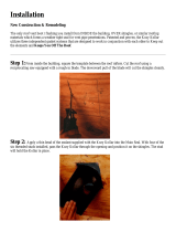
LOG INSTALLATION
This log set includes: (1) W5 Log (1) W6 Log (1) W7 Log (1) Klinker packet
(1) W8 Log (1) W9 Log (1) W10 Log (1) Rock wool ember packet
NOTE: The logs are numbered on the bottom side - refer to the instructions below for proper placement. The
base logs have mounting holes Incorporated into the bottom of the logs and should be positioned onto
the corresponding mounting studs. Alignment cut-outs have been designed into the logs for positioning.
Their location on the logs are represented as an (*) symbol in the photo below.
FIGURE 10A
Refer to the figure 10A above for steps #1 - #3:
1. Place back base log ‘W5' into position aligning the slots in the bottom of the log (one on each end) onto the
burner cover and the notched out section in the log around the pilot assembly. Once positioned, press down
slightly to secure in place.
2. Position the remaining base logs, ‘W6' & ‘W7' into the center of the burner as shown. Natural Gas models:
Push the logs back against the burner tube.
3. Carefully place the rock wool embers as desired onto the logs and burner tube to create additional glow. Do
not plug burner port holes or use excessively. Place the ‘klinkers’ onto the burner plate and in front of the
burner tube as shown above. Note: You will not use all the ‘embers’ in the packet - save for future use.
‘Klinkers’
CAUTION: DO NOT COVER THE BURNER PORTHOLES IN FRONT OF THE PILOT.
BLOCKING THESE PORTHOLES MAY RESULT IN DELAYED IGNITION OF THE BURNER.
FIGURE 10B
4. Position the ‘W8’ log, ‘W9' log & ‘W10' log onto the alignment cut-outs as shown in figure 10B.
INITIAL BURN PERIOD
During the initial burn period, the logs and refractory will discolor. This is normal and part of the curing
process. Once the curing process is complete (approximately 2-4 hours), the true color will return.
IMPORTANT: DO NOT BURN THIS FIREPLACE WITHOUT THE GLASS ASSEMBLY IN PLACE.
MAKE SURE THE HOMEOWNER IS AWARE OF THIS
!
Page 16

THERMOSTAT - WALL SWITCH - REMOTE INSTALLATION (OPTIONAL)
NOTE: INSTALLATION OF A THERMOSTAT OR WALL SWITCH SHOULD ONLY BE DONE BY A QUALIFIED
INSTALLER.
If desired, a thermostat (wireless style available), wall
switch, or remote control assembly may be used to
turn the fireplace ‘OFF’ and ‘ON’. ONLY one of these
may be installed. Follow instructions included with
each assembly.
NOTE: OPEN THE VALVE COVER TO EXPOSE THE
GAS VALVE AND WIRE CONNECTION ON THE
VALVE TERMINALS.
Disconnect the on/off rocker switch wires from the top
& bottom terminals on the gas valve.
Follow instructions included with the remote control.
Remote Control Wiring Diagram
CAUTION:
DO NOT
CONNECT HIGH VOLTAGE (115V) WIRE TO THE GAS VALVE!
REMOTE CONTROL USERS:
IMPORTANT: The insulated cover included with
the remote control must be placed over the remote
receiver to protect it from overheating.
CONTROL USERS
Run low-voltage (thermostat) wires from the terminals
on the gas valve to the desired location of the wall
switch or thermostat.
Attach the appropriate connector to each wall switch /
thermostat wire and connect to the top and bottom
terminals on the gas valve marked ‘TH’.
WALL SWITCH / THERMOSTAT USERS:
Thermostat Wiring Diagram
Page 17

COMPLETE THE INSTALLATION
1. A) Secure the stud tabs located on the sides of the unit to the stud walls.
B) Use screws (not provided) to secure the unit to the flooring through the holes located in the bottom of the
outer box.
IMPORTANT - MOBILE HOME INSTALLATIONS: THE FIREPLACE MUST BE SECURED TO THE
FLOOR.
C) Complete the fireplace walls, and the unit facing.
CAUTION: THE SURROUNDING WOOD CHASE OF THE OUTSIDE WALL MUST BE INSULATED TO PREVENT COLD AIR FROM ENTERING THE ROOM.
2. THIS STEP SHOULD ONLY BE DONE BY A QUALIFIED INSTALLER OR SERVICE TECHNICIAN:
A) Perform lighting and shutdown procedures as described on pages #20-21 . This should be done prior to
replacing the glass so that any necessary adjustments can be made and proper operation verified.
3. Replace the glass. Refer also to Figure 7, pg.11.
A) Align the slots in the top of the glass assembly over the tabs on the fireplace.
B) Place the glass assembly so it is flush with the front of the fireplace front.
C) Secure the assembly to the fireplace by pulling the two spring loaded handles (located under the firebox)
out and up over the latch brackets. Release, locking them into position.
4. Upper Grill - Install:
A) Line the rods of the grill up with the upper holes.
B) Place the rods in the holes and push up until the bottoms of the rods clear the glass frame.
C) Place the bottom of the rods into the lower holes and release. The grill will set down into place.
Remove:
A) Lift the upper grill up far enough to clear the bottom holes and pull bottom of grill out.
5. Lower grill - See Figure 12
Replace:
A) Remove the 1/4" nuts (B) from the lower
grill assembly.
B) Slip the bolt through the hinge (A).
C) Re-attach the 1/4" nut (B).
D) Repeat “A” through “C” for the remaining
hinge.
The grill is now in place. The grill may be lowered
for accessing the control valve, service, etc.
Remove:
A) Remove the 1/4" nuts (B) from the
lower grill assembly.
B) Pull the entire grill assembly out of
the hinges.
C) Re-attach the 1/4" nuts (B).
WARNING: DO NOT OPERATE THIS FIREPLACE WITH THE GLASS ASSEMBLY REMOVED, CRACKED OR BROKEN.
Re
p
lacement of the
g
lass assembl
y,
p
art #700-07T should be done b
y
a licensed or
q
ualified service
p
erson.
FIGURE 1
2
Page 18
/