Page is loading ...

VMAC – Vehicle Mounted Air Compressors
Toll Free: 1-888-241-2289
Fax: 1-250-740-3201
1
Installation Manual for VMAC
System DM00001
2011 - 2016 Ford SuperDuty
6.7L Diesel with PTO


VMAC – Vehicle Mounted Air Compressors
Toll Free: 1-888-241-2289
Fax: 1-250-740-3201
1
Installation Manual for VMAC System DM00001
2011 - 2016 Ford SuperDuty
6.7 L Diesel with PTO
General Information ......................................................................................................... 3
Before You Start ............................................................................ 3
Torque Specifications .................................................................... 3
Special Tools Required ................................................................. 3
Hose Information ........................................................................... 3
Important Safety Notice ................................................................. 4
Safety Messages ........................................................................... 4
Ordering Parts ............................................................................... 5
Limited Lifetime Warranty .............................................................. 5
Warranty Registration .................................................................... 5
Part 1: System Identification, Warranty and Warnings ............................................... 6
Part 2: Preparing for Installation .................................................................................... 8
2.1 Cab Clearance ......................................................................... 10
Part 3: Installing the Cooler, PTO, Compressor, and Regulator ................................ 12
3.1 Modifying the coolant hoses .................................................... 12
3.2 Installing the cooler .................................................................. 14
3.3 Installing the PTO .................................................................... 16
3.4 Installing the Compressor ........................................................ 17
3.5 Installing the Regulator ............................................................ 19
3.6 Installing the Air Intake ............................................................ 20
Part 4: Installing the Tank and Hoses ............................................................................ 23
4.1 Installing the Tank and Brackets ............................................. 23
4.2 Installing the Hoses ................................................................. 28
4.3 Adding Oil to the System ......................................................... 31
Part 5: Installing the Control Components ................................................................... 32
5.1 Wiring diagrams ....................................................................... 32
5.2 Installing the Components ....................................................... 34
5.3 Routing the In-cab Wiring ........................................................ 36
5.4 Connecting the In-cab Wiring .................................................. 37
5.5 Engine Bay PTO / Compressor Connections .......................... 39
Part 6: Completing and Testing the Installation ........................................................... 40
6.1 Finishing the installation .......................................................... 40
6.2 Safety Test .............................................................................. 40
6.3 Before Starting the Engine Checklist ....................................... 41
6.4 After Starting the Engine Checklist .......................................... 41
Part 7: Setup, Performance Testing and Adjustments ................................................ 42
7.1 Final Testing ............................................................................ 43
Part 8: Optional Accessory Installation ......................................................................... 44
Part 9: Air Receiver Tank................................................................................................. 45
Part 10: Accessory Products .......................................................................................... 46
Part 11: Warranty Registration ....................................................................................... 47

VMAC – Vehicle Mounted Air Compressors
Toll Free: 1-888-241-2289
Fax: 1-250-740-3201
2
Installation Manual for VMAC System DM00001
2011 - 2016 Ford SuperDuty
6.7 L Diesel with PTO
Document: 1930284
Changes and Revisions
Important Information
The information in this manual is intended for certified VMAC installers
who have been trained in installation procedures and for people with
mechanical trade certification who have the tools and equipment to
properly and safely perform the installation. Do not attempt this installation
if you do not have the appropriate mechanical training, knowledge and
experience.
Follow all safety precautions for mechanical work. Any grinding, bending
or restructuring operations for correct fit in modified trucks must follow
standard shop practices.
Notice
Manuals are subject to change without notice.
Registered Trademarks
All trademarks mentioned in this manual are the property of their
respective owners. Their use by VMAC is for identification of the
manufacturers’ products only and does not imply any affiliation or
endorsement by said companies.
Loctite®, Loctite® Klean N’ Prime™, Loctite® 242 and Loctite PST® are
registered trademarks of Henkel AG & Company KGaA.
Nylok® is a registered trademark of Nylok Fastener Corporation.
Ford® is registered trademarks of Ford Motor Company.
Copyright 2020
All trademarks used in this manual are the property of the respective copyright holder.
The contents of this manual may not be reproduced in any form without the express
written permission of VMAC, 1333 Kipp Road, Nanaimo, BC V9X 1R3.
Printed in Canada
Revision
Revision Details
Revised
by
Checked by
Implemented
Eng.
Tech.
Qual.
Mech.
Elec.
B
ECN 16-029 PTO adaptor plate upgrade
MSP
KRM
AJH
GB
AMG
10 May 2016
C
ECN 18-125 Add prp wire to Fig 5.3
MSP
N/A
SM
GB
AWG
14 June 2018
D
ECN: 20-201 PTO mount update
MSP
CAM MSP
N/A N/A 21 Oct. 2020

VMAC – Vehicle Mounted Air Compressors
Toll Free: 1-888-241-2289
Fax: 1-250-740-3201
3
General Information
Before You Start
Read this manual before attempting installation so that you can familiarize
yourself with the components and how they fit on the vehicle. Identify
variations for different engine models and different situations that are
listed in the manual. Open the package, unpack the components and
identify them.
Torque Specifications
All fasteners must be torqued to specifications. Use manufacturers torque
values for OEM fasteners. Apply Loctite 242 or equivalent on all
engine-mounted fasteners. Torque values are with Loctite applied
unless otherwise specified.
STANDARD GRADE 8 NATIONAL COARSE THREAD
Size
1/4
5/16
3/8
7/16
1/2
9/16
5/8
3/4
Foot-pound (ft-lb)
9
18
35
55
80
110
170
280
Newton meter (N•m)
12
24
47
74
108
149
230
379
STANDARD GRADE 8 NATIONAL FINE THREAD
Size
3/8
7/16
1/2
5/8
3/4
Foot-pound (ft-lb)
40
60
90
180
320
Newton meter (N•m)
54
81
122
244
434
METRIC CLASS 10.9
Size
M6
M8
M10
M12
M14
M16
Foot-pound (ft-lb)
4.5
19
41
69
104
174
Newton meter (N•m)
6
25
55
93
141
236
Special Tools Required
• Required: VMAC DM70 Ford Cab Clearancing tool (5900272).
Hose Information
Depending on other installed equipment, it might be necessary to move
the air/oil separation tank from its intended location. The hoses used in
VMAC compressor systems have a specific inner liner that is compatible
with our compressor oil. Use of hoses other than those supplied or
recommended by VMAC may cause compressor damage and may void
your warranty.
Please contact VMAC for non-standard length hoses, replacement hoses
or for further information.

VMAC – Vehicle Mounted Air Compressors
Toll Free: 1-888-241-2289
Fax: 1-250-740-3201
4
Important Safety Notice
The information contained in this manual is based on sound engineering
principles, research, extensive field experience and technical information.
Information is constantly changing with the addition of new models,
assemblies and service techniques. If a discrepancy is noted in this
manual, contact VMAC prior to initiating or proceeding with installation,
service or repair. Current information may clarify the issue. Any person
with knowledge of such discrepancies who performs service and repair
assumes all risks.
Only proven service procedures are recommended. Anyone who departs
from the specific instructions provided in this manual must first assure that
their safety and that of others is not being compromised and that there will
be no adverse effects on performance or the operational safety of the
equipment.
VMAC will not be held responsible for any liability, consequential
damages, injuries, loss or damage to individuals or to equipment as a
result of the failure of any person to properly adhere to the procedures set
out in this manual or standard safety practices. Safety should be your first
consideration in performing service operations. If you have any questions
concerning the procedures in this manual or require any more information
on details that are not included in this manual, please contact VMAC
before beginning repairs.
Safety Messages
This manual contains various warnings, cautions and notices that must be
observed to reduce the risk of personal injury during installation, service or
repair and the possibility that improper installation, service or repair may
damage the equipment or render it unsafe.
This symbol is used to call your attention to instructions
concerning your personal safety. Watch for this symbol, it points
out important safety precautions, it means, “Attention, be alert!
Your personal safety is involved”. Read the message that follows
and be alert to the possibility of personal injury or death. While it
is impossible to warn about every conceivable hazard, let good
common sense be your guide.
This symbol is used to call your attention to instructions on a
specific procedure that if not followed may damage or reduce the
useful life of the compressor.
This symbol is used to call your attention to additional instructions
or special emphasis on a specific procedure.

VMAC – Vehicle Mounted Air Compressors
Toll Free: 1-888-241-2289
Fax: 1-250-740-3201
5
Ordering Parts
To order parts, contact your VMAC dealer. Your dealer will ask for the
VMAC serial number, part number, description and quantity. To locate
your nearest dealer, call 1-800-738-8622 or online at www.vmacair.com
Limited Lifetime Warranty
The Compressor Assembly (excluding Inlet and Clutch, where applicable)
is warranted against manufacturer defects in materials and workmanship
for the lifetime of the Compressor Assembly. Restrictions apply – refer to
VMAC Warranty Policy and VMAC Limited Lifetime Warranty for full
details.
http://vmacair.com/support/warranty/
Warranty Registration
The VMAC warranty form is located at the back of this manual. This
warranty form must be completed and sent to VMAC at the time of
installation for any subsequent warranty claim to be considered valid.
There are 4 ways warranty forms can be submitted to VMAC:
Online
http://vmacair.com/support/warranty/
Email
Fax
(250) 740-3202
Mail
VMAC - Vehicle Mounted Air Compressors
1333 Kipp Road, Nanaimo, BC, Canada V9X 1R3

VMAC – Vehicle Mounted Air Compressors
Toll Free: 1-888-241-2289
Fax: 1-250-740-3201
6
Part 1: System Identification,
Warranty and Warnings
Preparation for installation is very important. Missing a step or an item can
cause problems in the installation or damage to components.
Check off each item as it is completed so that you do not miss
any preparation steps.
□ Check through the illustrated parts list to ensure that all components
are present and that they are in the correct quantity. If any
components are missing, have the system ID ready and call VMAC
technical support at (888) 241-2289.
□ Complete the warranty form. The VMAC warranty form is located at
the back of this manual, as well as online at:
http://vmacair.com/warranty/
This warranty form must be completed and returned to VMAC at the time
of installation for any subsequent warranty claim to be considered valid.
The System Identification Number Plate must be attached to
the vehicle at the time of installation. This plate provides
information that allows VMAC to assist with parts and
repairs.
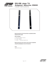
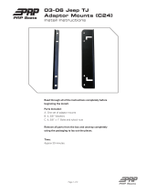
□ Mark and drill 2 7/64 in holes in the top of the cross member in front of
the OEM air filter box. Secure the plate with supplied self- tapping
screws. (Figure 1.1)
Figure 1.1 – System Identification Plate

VMAC – Vehicle Mounted Air Compressors
Toll Free: 1-888-241-2289
Fax: 1-250-740-3201
7
□ As part of the installation process, ensure that the operating
instruction label is affixed in an obvious location so that it can be seen
by vehicle operators. A good spot for this is usually on the inside of
the door or on the panel underneath the steering wheel (Figure 1.2).
Figure 1.2 – Operating Instruction Label
□ To alert any technicians that may service the vehicle, affix the warning
label in the engine compartment near the hood latch in a visible
location. Thoroughly clean the selected area before affixing the label
(Figure 1.3).
Figure 1.3 – Warning Label

VMAC – Vehicle Mounted Air Compressors
Toll Free: 1-888-241-2289
Fax: 1-250-740-3201
8
Part 2: Preparing for Installation
Do not use a test light to probe for power on vehicle
circuits, the increased current draw of the test light may
damage components.
Preparation for installation is very important. Missing an item can cause
problems in the installation or even damage to components. Check off each
item as it is completed so that you do not miss any preparation steps.
Ensure that you have filled out the VMAC Warranty
Registration. Install the System Identification Number Plate
and operating instruction label. (Please see Part 1 for
details).
Due to variations in service body design and other
equipment, VMAC cannot recommend mounting locations
for the remote air filter housing. You will need to determine
this location and order sufficient ducting to route from the
remote air filter housing to the compressor air inlet. Include
enough additional ducting to allow for appropriate routing
away from hot, sharp or moving parts. (Figure 2.1)
Figure 2.1 – Determine Remote Air Filter location
□ Determine your remote air filter duct length:
• For optimum performance, the duct length should be minimized.
• The kit includes 8 ft. of hose, which can be cut to length.
• Longer hose may be purchased from VMAC, or a hose supplier.
▪ VMAC P/N: 1700650
▪ New Line P/N: NL6025-200
□ Locate the blunt-cut OEM SEIC wire harness, on the driver side just
below the OBDII port. You will need to find the transmission park
signal, (blue with grey stripe wire).
□ Use a multi-meter to verify the transmission park signal. Turn the key
to the “IGN2” position, (do not start the truck), to supply power to the
dash display. The resistance should read close to 0 Ω in park and
Approximate location
of compressor inlet
Possible remote
air filter location.

VMAC – Vehicle Mounted Air Compressors
Toll Free: 1-888-241-2289
Fax: 1-250-740-3201
9
open circuit in all other gears. If this is correct, put the car in park and
turn the key to the off position.
There are multiple blue wires with various coloured stripes.
The transmission park signal needs to be electrically verified
with a multi-meter to ensure the correct wire is used.
□ Mark the transmission park signal wire for connection later in “Part 5
Installing the Control Components”.
□ Disconnect both the driver and passenger side batteries.
□ Drain coolant from the primary radiator into a clean container for re-
use later. The drain can be found on the driver side of the radiator.
Close the drain spigot once the coolant has been drained.
□ Remove the tab on the shift linkage bracket beside the PTO port to
provide clearance to install the PTO and compressor. (Figure 2.2)
Figure 2.2 – Modify shift linkage
Cut off tab

VMAC – Vehicle Mounted Air Compressors
Toll Free: 1-888-241-2289
Fax: 1-250-740-3201
10
2.1 Cab Clearance
It is extremely important to ensure that no foreign particles
or debris can enter the PTO port on the transmission.
□ Apply the park brake and chock the rear wheels.
□ Remove the 6 bolts retaining the cover on the PTO port. A small
amount of transmission fluid may drip from the cover and seal plates.
Retain the seal plate.
□ Using the seal plate from the transmission cover to protect the
transmission port, install the clearancing tool onto the PTO port using
the 6 supplied bolts. Make sure the clearancing ram is installed in the
bracket before install. (Figure 2.3)
Figure 2.3 – Modifying the cab clearance
□ Using a jack or porta-power unit, raise the clearancing ram until the
cab stops moving. On an empty chassis cab, this is approximately 1
in. (Figure 2.4)
Figure 2.4 – Modifying the floor clearance
Install using the 6
supplied M10 bolts
Ram

VMAC – Vehicle Mounted Air Compressors
Toll Free: 1-888-241-2289
Fax: 1-250-740-3201
11
□ Mark the current position for reference. (Figure 2.5)
Figure 2.5 – Modifying the floor clearance
□ Continue to raise the clearancing ram 2 notches (approx. 1/2 in) on
the side of the bracket as shown. (Figure 2.6.)
Figure 2.6 – Modifying the floor clearance
□ Lower the clearancing ram slowly.
□ Remove the clearancing tool from the PTO port and cover the port
until ready to proceed with the PTO installation.
Mark a line from
the bottom step
1/2 in

VMAC – Vehicle Mounted Air Compressors
Toll Free: 1-888-241-2289
Fax: 1-250-740-3201
12
Part 3: Installing the Cooler, PTO,
Compressor, and Regulator
3.1 Modifying the coolant hoses
□ Remove the lower primary coolant hose that is attached to the primary
cooler and engine. (Figure 3.1)
Figure 3.1 – Modifying the lower radiator hose
□ Cut the plastic cuff securing the OEM quick connect to the engine side
coolant hose. Discard the OEM quick connect. (Figure 3.2)
Figure 3.2 – Modifying the lower radiator hose
From radiator
To engine
OEM quick
connect
Cut cuff

VMAC – Vehicle Mounted Air Compressors
Toll Free: 1-888-241-2289
Fax: 1-250-740-3201
13
□ Cut the radiator side coolant hose 8 in from the OEM quick connect
and discard the short section of hose with the OEM quick connect.
(Figure 3.3)
Figure 3.3 – Modifying the lower radiator hose
8 in
Discard this section
OEM quick
connect

VMAC – Vehicle Mounted Air Compressors
Toll Free: 1-888-241-2289
Fax: 1-250-740-3201
14
3.2 Installing the cooler
□ Apply the supplied loom to the 1/2 in oil hoses.
□ Connect the shortest 1/2 in hose to the passenger side of the cooler
and orient as shown. Leave the fitting hand tight until ready for final
alignment once the Air Oil Separator Tank (AOST) is in place. (Figure
3.4).
Figure 3.4 – Attaching the cooler hoses
□ Connect the longest 1/2 in hose to the driver side of the cooler and
orient as shown. Leave the fitting hand tight until ready for final
alignment once the AOST is in place. (Figure 3.4)
Do not strike the impact sensor as this could cause the
airbags to actuate.
□ Position the cooler in the center of the cross-member so that it is just
above the sway bar with the oil ports facing up. (Figure 3.5)
Figure 3.5 – Mounting the oil cooler
!
Impact
sensor
Fog light
connector
location
Cross member
Short 1/2 in hose
long 1/2 in hose
Apply Loctite
to the 4 bolts

VMAC – Vehicle Mounted Air Compressors
Toll Free: 1-888-241-2289
Fax: 1-250-740-3201
15
□ Apply Loctite to the 4 bolts and install them, along with the washers,
through the flat mounting straps on the front of the cross member on
each side of the impact sensor. (Figure 3.5)
□ Thread the bolts into the matching holes on the cooler mounts hand
tight only, this will allow the cooler to be repositioned if necessary
after the coolant hoses have been attached. (Figure 3.5)
□ Install the radiator side coolant hose and secure with supplied hose
clamp. (Figure 3.6)
Figure 3.6 – Attaching the cooler hoses
□ Once the radiator side coolant hose is secured, torque the cooler
mount bolts to specification.
□ Install the engine side coolant hose and secure using the supplied
hose clamp. (Figure 3.6)
If any kinking of the hose occurs, trim the cooler end of the
coolant hoses as required.
□ Torque the cooler mounting bolts to specification.
To radiator
To engine

VMAC – Vehicle Mounted Air Compressors
Toll Free: 1-888-241-2289
Fax: 1-250-740-3201
16
3.3 Installing the PTO
It is extremely important to ensure that no foreign particles
or debris can enter the PTO port on the transmission.
□ Raise the front of the vehicle and support the axle on axle stands (or
appropriate blocking).
Ensure the truck is fully supported on axle stands before
working under it.
On 4x4 vehicles, mark the front drive shaft with a grease pen
(or similar permanent marker) for re-alignment later. Unbolt
the front of the drive shaft and pivot it out of the way to allow
room to install the compressor.
□ Follow the mechanical portion of the OEM PTO installation
instructions.
The PTO electrical installation will be covered in “Part 5
Control Components” and differs from the OEM PTO
instructions.
□ Slide the washers onto the 3 supplied bolts and apply Loctite to the
threads.
□ Using 2 of the bolts in the locations shown, mount the adaptor plate to
the PTO; ensure the adaptor plate is snug but do not torque the bolts
(Figure 3.7).
Figure 3.7 – Mounting the PTO Adaptor Plate
□ Install the remaining bolt and washer.
□ Using a torque wrench, torque the 3 bolts to 40 ft. lb.

VMAC – Vehicle Mounted Air Compressors
Toll Free: 1-888-241-2289
Fax: 1-250-740-3201
17
3.4 Installing the Compressor
□ Temporarily install the (×2) supplied guide pins into the top (longer
pin) and lower left (shorter pin) threaded holes in the adapter plate
(Figure 3.8).
Figure 3.8 – Install alignment guides
□ To assist with mating the compressor and the PTO, align a groove in
the PTO spline shaft with a tooth on the compressor’s input shaft. The
top mounting hole for the compressor can be used as a reference.
□ Apply a generous amount of spline grease (supplied with the PTO) to
both splines. Ensure the grooves of each are fully filled.
Thread guide
pins until they
are flush with
back face of
adaptor plate
Thread guide
pins until they
are flush with
back face of
adaptor plate

VMAC – Vehicle Mounted Air Compressors
Toll Free: 1-888-241-2289
Fax: 1-250-740-3201
18
□ Slide the compressor forward onto the guide pins, and push forward
until the compressor is fully mated with the PTO adaptor (Figure 3.9).
Figure 3.9 – Install alignment guides
□ Apply blue Loctite and install 1 of the 3 supplied bolts with flat washer
into the available threaded hole (Figure 3.10).
Figure 3.10 – Securing the compressor
□ Apply Loctite to the remaining 2 compressor mount bolts.
/