1
Standard Anemometer
Installation Manual
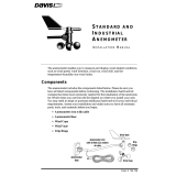
The anemometer measures wind-related conditions such as wind speed, wind
direction, wind run, wind chill, and the temperature-humidity-sun-wind index.
It can be used with an EnvironMonitor Node to add wind data to an
EnvironMonitor system, as well as a replacement anemometer to your Davis
weather station. Installed in a Sensor Transmitter, it can be used to include
additional wind stations in your existing system when reporting to a
WeatherLink Live.
Components
The anemometer includes the components listed below. Be sure you have all
listed components before continuing. Assess your installation and make sure
you have all necessary parts, tools, and materials pictured below before you
begin.
Wind Cups
A
nemometer
Base
Anemometer Arm
with 40 feet (12.2 meters)
of cable
Wind Vane
Hardware
The hardware kit contains the items
most commonly needed for the
installation of the anemometer.
Which items you use from the kit
depend on where you install your
unit. You may need to adapt or
purchase additional hardware to fit
your individual requirements.
Tools and Materials Needed
You will need the following tools
and m
aterials to install your
anemometer:
• Cable Clips or Weather-Resistant Cable Ties
Note: Make sure the clips or ties you use to secure the anemometer cable have screw holes or other
means for mounting the cable. Do not use metal staples to secure the cables.

Testing the Anemometer
2
• Stainless Steel Hose Clamps
• Small Screwdrivers
• Adjustable Wrench
• Hand-Held Compass or Local Area Map
Testing the Anemometer
Before beginning your installation, follow the instructions below to test the
anemometer wind speed and wind direction functions.
1. Connect the anemometer cable to the appropriate connector on your
junction box.
2. Push the wind cups onto the smaller of the two stainless steel shafts at the
end of the arm.
3. Spin the wind cups gently. You haven’t secured them yet, and if you spin
them too hard you may knock them off.
4. Check the display on your weather station to make sure you are getting a
wind speed reading.
5. Grasp the upper, larger of the two stainless steel shafts at the end of the arm
with your fingers and twist the shaft about 1/2 turn.
6. Check the display to make sure the wind direction reading on your display
changes.
Note: The wind direction readings will not change as rapidly as you turn the shaft. The station uses a low
pass filter to smooth out the constant small shifts in wind direction and keep the direction display from
jumping about in gusty winds.
7. Disconnect the cables when you are finished testing the anemometer.
Assembling the Anemometer
Attach the wind cups to the anemometer and check the mounting base
orientation before you install it.

Choosing the Best Anemometer Location
3
Attaching the Wind Cups
Before installing the anemometer, attach the wind cups. Wait until you have
installed the anemometer before you attach the wind vane.
1. Push the wind cups onto the smaller of the
two stainless steel shafts.
Tighten set
screw with
Allen wrench
Push cups onto
stainless steel
shaft
Attaching the Wind Cups
2. Slide the wind cups as far up the shaft as possible.
3. Use the allen wrench provided to tighten the set screw on the side of the
win
d cups.
4. Spin the wind cups. If they do not spin freely
, loosen the set screw, lower
the cups slightly, then retighten the set screw.
5. Repeat Step 4 until the wind cups spin freely.
Choosing the Best Anemometer Location
Use the following guidelines to determine the best location for your
anemometer.
• Install the anemometer in a location where wind flow is unobstructed by
trees and nearby bu
ildings.
• For the most accurate readings, the anemome
ter should be mounted at least
4 feet (1.2 m) above the roof line.
• You may do this by mounting the anemometer on a television antenna mast,
a wooden post, or
a metal pipe.
• Make sure the antenna mast or metal pipe is properly grounded. You may
want
to use Davis’ Grounding Kit.
• If you are not certain about how to ground your installation, consult a
qual
ified professional for national and local codes.
Note: If you live in an area subject to frequent thunderstorms, installing a lightning rod nearby can reduce
the risk of damage.
Orient the Wind Vane
The wind vane rotates 360° to display current and dominant wind directions
on the
compass rose of the console display. To obtain accurate readings, the
vane must be correctly oriented when mounting the anemometer outside. By

Installing the Anemometer
4
default, the wind vane reports the correct wind direction if the anemometer
arm points true north.
To ensure correct orientation of the wind vane, mount the anemometer so that
the arm
points true north.
Installing the Anemometer
Installing on a Sensor Mounting Arm
Consult the Sensor Mounting Arm manual for instructions.
Check the Anemometer Base Orientation
You will need to know which way to orient the base before installing it.
1. Insert the anemometer arm into the base.
2. Attempt to push the #4-40 x 1 1/4" pan head screw through the holes in the
arm
and the base.
3. If the screw does not slide easily through the holes, rotate the base 180° to
lin
e up the opposite holes, then try again.
Installing the Base on a Wooden Post or Surface
1. Hold the anemometer base against the wood
surface
and use a pencil to mark the location
of the four holes on the base.
Attaching base to wooden post
2. Use a drill with a 3/16" (5-mm) drill bit to
make pilot holes in these locations.
3. Drive the lag screws through the holes in the
anemome
ter base and into the wood.
Installing on Antenna Mast or Metal
Pipe
Attaching base to a pipe
using U-bolts
On an antenna mast or pipe with outside diameter of
7/8" to 1 1/4" (22 to 32 mm):
1. Hold the anemometer base against the pipe and
insert t
he two U-bolts through the back of the base
so that the U-bolts wrap around the pipe.
2. Place a 1/4" washer and a 1/4-20 hex nut over
each
end of the U-bolts and use a wrench to tighten the
hex nuts.

Installing the Anemometer
5
On a metal pipe with outside diameter greater than 11/4 inch (32 mm):
1. Use two stainless steel hose clamps to attach the
mo
unting base to masts or pipes larger than 1 1/4"
diameter, large enough to fit around the mast or pipe
and the anemometer base.
Attaching base to a pipe
using hose clamps
2. Hold the anemometer base against the pipe and
fasten the hose clamps over the anemometer base
and around the metal mast or pipe.
Attaching Arm to Base
1. Insert the anemometer arm into the
anemome
ter base.
Inserting arm into base
Guide the anemometer cable through
the slot as you insert the arm.
2. Insert the pan head screw into one of
the ho
les in the base and slide it
through the arm.
3. Secure the pan head screw using
the flat washer
, lock washer, and
hex nut as shown.
Attaching the anemometer arm to the base

Maintenance
6
Installing the wind vane
1. Slide the wind vane down onto the
shaft as far as it will go. (Because of the
shape of the shaft, the vane will only go on one way.)
2. Use the allen wrench provided to tighten the set screw on the side of the
win
d vane.
3. Test your assembly by pointing the wind vane in any direction and (using
the compass
or map as a guide) making sure the console displays the correct
wind direction.
4. Because of the low pass filter used by the station, allow
the wind direction
reading approximately 5 seconds to stabilize after you turn the vane.
5. Spin the wind cups to make sure you get a wind speed reading. Readjust the
cups if
necessary.
6. Secure the cable to the metal mast or pipe with
electrical tape. Secure the
rest of the cable according to the directions below.
Securing the Cable
To prevent fraying or cutting the anemometer
cable where it is exposed to
weather, secure it so
it doesn’t whip about in the wind. Use cable clips
or weather resistant cable ties to secure the cable.
Place clips or ties approximately every 3 to 5 feet
(1 to 1.6 m).
Securing cable
Note: Do not use metal staples to secure cables. Metal staples can cut the cables.
Maintenance
Your anemometer does not require any regular maintenance.
CAUTION: DO NOT attempt to lubricate the wind cup shaft and bearings or the wind vane
shaft. Natural or synthetic lubricants will inhibit the normal operation of the
anemometer.

Troubleshooting
7
Troubleshooting
While your anemometer is designed to provide years of trouble-free operation,
occasionally problems may arise. If you are having a problem with your unit,
please check the following troubleshooting procedures before sending the unit
in for repair. You will be able to solve many of the problems yourself. If, after
checking these procedures you are unable to solve the problem, please call
Davis Technical Support for further instructions (
see “Contacting Davis
Instruments Technical Support” on page 8.) Please do not return your unit for
repair without receiving prior authorization from Davis Technical Support.
Wind speed reads 0 all the time or intermittently or wind
direction reading is dashed out
• Make sure anemometer is plugged into jack marked WIND on junction box.
• Check for broken wire along length of anemometer cable. Carefully check
areas where the cable has been secured.
• Try dropping the wind cups approximately 1/16" to 1/8" (1.5 to 3 mm)
lower on the mounting shaft. Use the included Allen wrench to loosen and
retighten the wind cup assembly.
• If you still do not get a reading, the problem is with the anemometer.
Contact Davis Technical Support for return authorization.
Wind speed reading seems too high or too low
• Check installation by spinning wind cups. If the wind cups spin freely and
the weather station displays a wind speed, the wind cups are installed
correctly. If the wind cups don’t spin freely, then try dropping the wind cups
approximately 1/16" to 1/8" (1.5 to 3 mm).
• Check calibration number and adjust if necessary.
• Check for any obstructions blocking the wind near the anemometer.

Standard Anemometer Installation Manual
Product Number: 7911
Document Part Number: 7395.032 Rev G (June 25, 2019)
© Davis Instruments Corp. 2019. All rights reserved.
Information in this document subject to change without notice. Davis Instruments Quality Management
System is ISO 9001 certified.
3465 Diablo Avenue, Hayward, CA 94545-2778 U.S.A.
510-732-9229 • Fax: 510-732-9188
®
[email protected] • www.davisinstruments.com
Contacting Davis Instruments Technical Support
For questions about installing or operating your Anemometer, please contact
Davis Technical Support. We’ll be glad to help.
Online www.davisinstruments.com
See the Weather Support section for copies of user
manuals, product specifications, application notes,
software updates, and more.
E-mail support@davisinstruments.com
Telephone (510) 732-7814
Monday - Friday, 7:00 a.m. - 5:30 p.m. Pacific Time.
Specifications
Wind Direction
Accuracy: .........................................................................
±3°
Wind Speed
Range:.............................................................................0 to 200 mph., 1 to 322 kph,
1 to 173 knots,0.5 to 89 m/s
Accuracy:.........................................................................
±2 mph (3 kph, 2k ts,1 m/s) or ±5%,
whichever is greater
/