ALLURE TM WS1 SERIES
NuTone ° .o .ooo
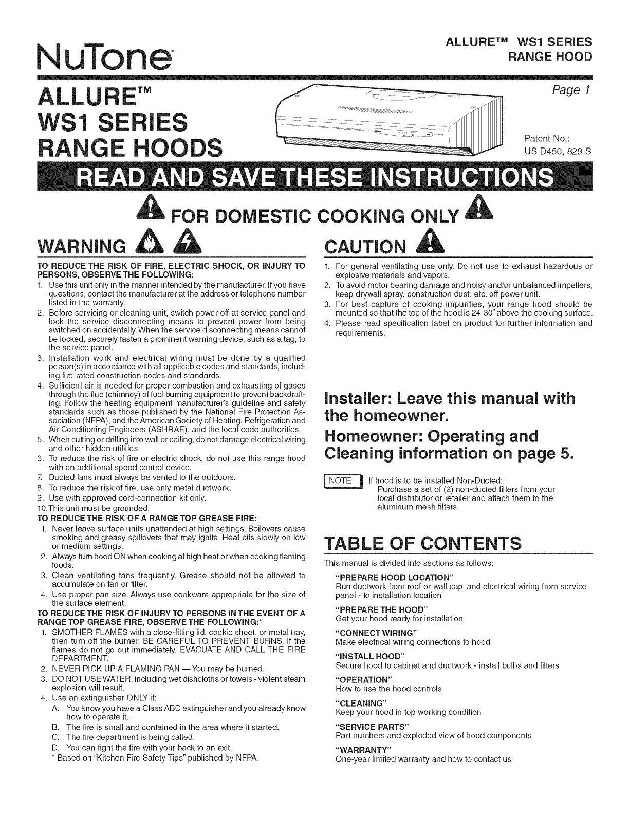
ALLU E'" Page l
WSl ES
Patent No.:
A GE HOO oso,,0, s
FOR DOMESTIC COOKING ONLY
CAUTION
TO REDUCE THE RISK OF FIRE, ELECTRIC SHOCK, OR iNJURY TO
PERSONS, OBSERVE THE FOLLOWING:
1. Use this unit only in the manner intended by the manufacturer, ifyou have
questions, contact the manufacturer at the address or telephone number
listed in the warranty.
2. Before servicing or cleaning unit, switch power off at service panel and
lock the service disconnecting means to prevent power from being
switched on accidentally. When the service disconnecting means cannot
be locked, securely fasten a prominent warning device, such as a tag, to
the service panel.
3. installation work and electrical wiring must be done by a qualified
person(s) inaccordance with all applicable codes and standards, includ-
ing fire-rated construction codes and standards.
4. Sufficient air is needed for proper combustion and exhausting of gases
through the flue (chimney) of fuel burning equipment to prevent backdraft-
ing. Follow the heating equipment manufacturer's guideline and safety
standards such as those published by the National Fire Protection As-
sociation (NFPA), and the American Society of Heating, Refrigeration and
Air Conditioning Engineers (ASHRAE), and the local code authorities.
5. When cutting or drilling intowall or ceiling, do not damage electrical wiring
and other hidden utilities.
6. To reduce the risk of fire or electric shock, do not use this range hood
with an additional speed control device.
Z Ducted fans must always be vented to the outdoors.
8. To reduce the risk of fire, use only metal ductwork.
9. Use with approved cord-connection kit only.
10.This unit must be grounded.
TO REDUCE THE RISK OF A RANGE TOP GREASE FIRE:
1. Never leave surface units unattended at high settings. Boilovers cause
smoking and greasy spillovers that may ignite. Heat oils slowly on low
or medium settings.
2. Always turn hood O N when cooking at high heat or when cooking flaming
foods.
3. Clean ventilating fans frequently. Grease should not be allowed to
accumulate on fan or filter.
4. Use proper pan size. Always use cookware appropriate for the size of
the surface element.
TO REDUCE THE RISK OF INJURY TO PERSONS INTHE EVENT OFA
RANGE TOP GREASE FIRE, OBSERVE THE FOLLOWING:*
1. SMOTHER FLAMES with a close-fitting lid, cookie sheet, or metal tray,
then turn off the burner. BE CAREFUL TO PREVENT BURNS. if the
flames do not go out immediately, EVACUATE AND CALL THE FiRE
DEPARTMENT.
2. NEVER PiCK UPA FLAMING PAN --You may be burned.
3. DO NOT USE WATER, including wet dishcloths or towels - violent steam
explosion will result.
4. Use an extinguisher ONLY if:
A. You know you have a Class ABC extinguisher and you already know
how to operate it.
B. The fire is small and contained in the area where it started.
C. The fire department is being called.
D. You can fight the fire with your back to an exit.
* Based on "Kitchen Fire Safety Tips" published by NFPA.
1. For general ventilating use only. Do not use to exhaust hazardous or
explosive materials and vapors.
2. To avoid motor bearing damage and noisy and/or unbalanced impellers,
keep drywall spray, construction dust, etc. off power unit.
3. For best capture of cooking impurities, your range hood should be
mounted so that the top of the hood is 24-30" above the cooking surface.
4. Please read specification label on product for further information and
requirements.
Installer: Leave this manual with
the homeowner.
Homeowner: Operating and
Cleaning information on page 5.
If hood is to be installed Non-Ducted:
Purchase a set of (2) non-ducted filters from your
local distributor or retailer and attach them to the
aluminum mesh filters.
TABLE OF CONTENTS
This manual isdivided into sections as follows:
"PREPARE HOOD LOCATION"
Run ductwork from roof or wall cap, and electrical wiring from service
panel - to installation location
"PREPARE THE HOOD"
Get your hood ready for installation
"CONNECT WIRING"
Make electrical wiring connections to hood
"INSTALL HOOD"
Secure hood to cabinet and ductwork - install bulbs and filters
"OPERATION"
How to use the hood controls
"CLEANING"
Keep your hood in top working condition
"SERVICE PARTS"
Part numbers and exploded view of hood components
"WARRANTY"
One-year limited warranty and how to contact us


