WAGO 750-468 User manual
- Category
- Stroboscopes & disco lights
- Type
- User manual
This manual is also suitable for

WAGO-I/O-SYSTEM 750
Manual
750-652
Serial Interface RS-232 / RS-
485
Configurable
Version 1.4.0

2 WAGO-I/O-SYSTEM 750
750-652 Serial Interface RS-232 / RS-485
Manual
Version 1.4.0
© 2015 by WAGO Kontakttechnik GmbH & Co. KG
All rights reserved.
WAGO Kontakttechnik GmbH & Co. KG
Hansastraße 27
D-32423 Minden
Phone: +49 (0) 571/8 87 – 0
Fax: +49 (0) 571/8 87 – 1 69
Web: http://www.wago.com
Technical Support
Phone: +49 (0) 571/8 87 – 5 55
Fax: +49 (0) 571/8 87 – 85 55
Every conceivable measure has been taken to ensure the accuracy and
completeness of this documentation. However, as errors can never be fully
excluded, we always appreciate any information or suggestions for improving the
documentation.
We wish to point out that the software and hardware terms as well as the
trademarks of companies used and/or mentioned in the present manual are
generally protected by trademark or patent.

WAGO-I/O-SYSTEM 750 Table of Contents 3
750-652 Serial Interface RS-232 / RS-485
Manual
Version 1.4.0
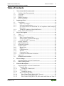
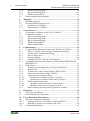
Table of Contents
1 Notes about this Documentation ................................................................. 6
1.1 Validity of this Documentation ................................................................. 6
1.2 Copyright ................................................................................................... 6
1.3 Symbols ..................................................................................................... 7
1.4 Number Notation ....................................................................................... 9
1.5 Font Conventions ...................................................................................... 9
2 Important Notes ......................................................................................... 10
2.1 Legal Bases ............................................................................................. 10
2.1.1 Subject to Changes ............................................................................. 10
2.1.2 Personnel Qualifications ..................................................................... 10
2.1.3 Use of the WAGO-I/O-SYSTEM 750 in Compliance with Underlying
Provisions ........................................................................................... 10
2.1.4 Technical Condition of Specified Devices ......................................... 11
2.2 Safety Advice (Precautions) .................................................................... 12
3 Device Description ..................................................................................... 14
3.1 View ........................................................................................................ 18
3.2 Connectors ............................................................................................... 19
3.2.1 Data Contacts/Internal Bus ................................................................. 19
3.2.2 Power Jumper Contacts/Field Supply ................................................ 20
3.2.3 CAGE CLAMP
®
Connectors ............................................................. 22
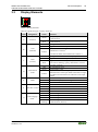
3.3 Display Elements .................................................................................... 23
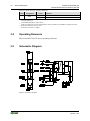
3.4 Operating Elements ................................................................................. 24
3.5 Schematic Diagram ................................................................................. 24
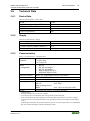
3.6 Technical Data ........................................................................................ 25
3.6.1 Device Data ........................................................................................ 25
3.6.2 Supply ................................................................................................. 25
3.6.3 Communication .................................................................................. 25
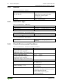
3.6.4 Interface .............................................................................................. 26
3.6.5 Connection Type ................................................................................ 26
3.6.6 Climatic Environmental Conditions ................................................... 26
3.7 Approvals ................................................................................................ 27
3.8 Standards and Guidelines ........................................................................ 28
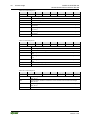
4 Process Image ............................................................................................. 29
4.1 Operating Modes for Serial Transmission .............................................. 29
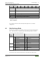
4.2 Data Exchange Mode .............................................................................. 31
5 Function Description ................................................................................. 33
5.1 Operating Modes for Serial Transmission .............................................. 33
5.1.1 Transmit Data ..................................................................................... 33
5.1.1.1 Continuous Transmission .............................................................. 33
5.1.2 Receive Data ....................................................................................... 34
5.1.2.1 Continuous Receipt ........................................................................ 34
5.1.3 RS-232 Operating Mode..................................................................... 35
5.1.3.1 Flow Control Using XON-/XOFF Protocol .................................. 35
5.1.3.2 Flow Control Using RTS/CTS ....................................................... 35
5.1.3.3 Flow Control Using RTS/CTS, RTS with Lead/Follow-on Time . 35

4 Table of Contents WAGO-I/O-SYSTEM 750
750-652 Serial Interface RS-232 / RS-485
Manual
Version 1.4.0
5.1.4 RS-485 Operating Mode..................................................................... 36
5.1.5 RS-422 Operating Mode..................................................................... 36
5.1.6 DMX Operating Mode ....................................................................... 36
5.2 Data Exchange Operating Mode ............................................................. 37
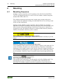
6 Mounting ..................................................................................................... 38
6.1 Mounting Sequence ................................................................................. 38
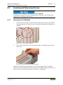
6.2 Inserting and Removing Devices ............................................................ 39
6.2.1 Inserting the I/O Module .................................................................... 39
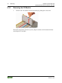
6.2.2 Removing the I/O Module .................................................................. 40
7 Connect Devices ......................................................................................... 41
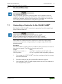
7.1 Connecting a Conductor to the CAGE CLAMP
®
................................... 41
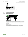
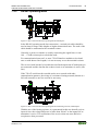
7.2 Connection Examples .............................................................................. 42
7.2.1 RS-232 Operating Mode..................................................................... 42
7.2.2 RS-485 Operating Mode..................................................................... 43
7.2.3 RS-422 Operating Mode..................................................................... 44
7.2.4 DMX Operating Mode ....................................................................... 45
7.2.5 Data Exchange Mode ......................................................................... 45
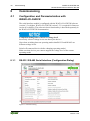
8 Commissioning ........................................................................................... 46
8.1 Configuration and Parameterization with WAGO-I/O-CHECK ............. 46
8.1.1 RS-232 / RS-485 Serial Interface (Configuration Dialog) ................. 46
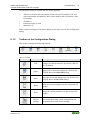
8.1.2 Toolbar on the Configuration Dialog ................................................. 47
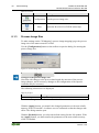
8.1.3 Process Image Size ............................................................................. 48
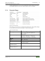
8.1.4 Parameter Range ................................................................................. 49
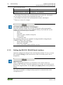
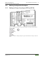
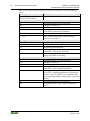
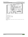
8.1.5 Setting the RS-232 / RS-485 Serial Interface ..................................... 50
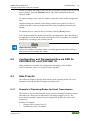
8.2 Configuration and Parameterization via GSD for PROFIBUS DP and
PROFINET IO ........................................................................................ 51
8.3 Data Transfer ........................................................................................... 51
8.3.1 Example of Operating Modes for Serial Transmission ...................... 51
8.3.2 Initialization ........................................................................................ 52
8.3.3 Transmission of the Character String "Hello World!" ....................... 53
8.3.4 Receiving the Character String "WAGO" .......................................... 54
8.3.5 Operation with Continuous Send........................................................ 55
8.3.5.1 Transmission of a Block of One to 512 Bytes ............................... 55
8.3.5.2 Transmission of a Block of More than 512 Bytes ......................... 55
8.3.6 DMX Application Example ................................................................ 57
8.3.6.1 Operation with Deactivated Continuous Send ............................... 57
8.3.6.2 Operation with Activated Continuous Send .................................. 57
8.3.7 Data Exchange Operating Mode Application Example ..................... 58
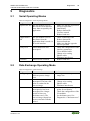
9 Diagnostics .................................................................................................. 59
9.1 Serial Operating Modes ........................................................................... 59
9.2 Data Exchange Operating Mode ............................................................. 59
10 Use in Hazardous Environments .............................................................. 60
10.1 Marking Configuration Examples ........................................................... 61
10.1.1 Marking for Europe According to ATEX and IEC-Ex ...................... 61
10.1.2 Marking for America According to NEC 500 .................................... 66
10.2 Installation Regulations ........................................................................... 67

WAGO-I/O-SYSTEM 750 Table of Contents 5
750-652 Serial Interface RS-232 / RS-485
Manual
Version 1.4.0
10.2.1 Special Conditions for Safe Use
(ATEX Certificate TÜV 07 ATEX 554086 X) .................................. 68
10.2.2 Special Conditions for Safe Use
(ATEX Certificate TÜV 12 ATEX 106032 X) .................................. 69
10.2.3 Special Conditions for Safe Use
(IEC-Ex Certificate TUN 09.0001 X) ................................................ 70
10.2.4 Special Conditions for Safe Use
(IEC-Ex Certificate IECEx TUN 12.0039 X) .................................... 71
10.2.5 Special Conditions for Safe Use
According to ANSI/ISA 12.12.01 ...................................................... 72
11 Appendix ..................................................................................................... 73
11.1 Configuration and Parameterization via GSD for PROFIBUS DP and
PROFINET IO ........................................................................................ 73
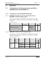
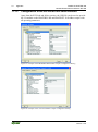
11.1.1 Configuration of the RS-232/RS-485 Interface .................................. 73
11.1.1.1 PROFIBUS DP (750-333, 750-343, 750-833) Fieldbus Coupler
PROFINET IO (750-370) Fieldbus Coupler ................................. 73
11.1.1.2 PROFINET IO (750-375, 750-377) Fieldbus Coupler .................. 73
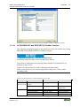
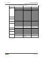
11.1.2 Configuration of the RS-232/RS-485 Serial Interface ....................... 74
11.1.2.1 All PROFIBUS DP and PROFINET IO Fieldbus Couplers .......... 75
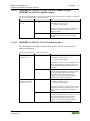
11.1.2.2 PROFIBUS DP (750-333, 750-343, 750-833) Fieldbus Coupler
PROFINET IO (750-370) Fieldbus Coupler ................................. 77
11.1.2.3 PROFINET IO (750-375, 750-377) Fieldbus Coupler .................. 77
List of Figures ...................................................................................................... 78
List of Tables ........................................................................................................ 79

6 Notes about this Documentation WAGO-I/O-SYSTEM 750
750-652 Serial Interface RS-232 / RS-485
Manual
Version 1.4.0
1 Notes about this Documentation
Always retain this documentation!
This documentation is part of the product. Therefore, retain the documentation
during the entire service life of the product. Pass on the documentation to any
subsequent user. In addition, ensure that any supplement to this documentation is
included, if necessary.
1.1 Validity of this Documentation
This documentation is only applicable to the I/O module 750-652 (Serial Interface
RS-232 / RS-485) and the variants listed in the table below.
Table 1: Variants
Item Number/Variant
Designation
750-652
Serial Interface RS-232 / RS-485
750-652/025-000
Serial Interface RS-232 / RS-485/T
Documentation Validity for Variants
Unless otherwise indicated, the information given in this documentation applies to
listed variants.
The I/O module 750-652 shall only be installed and operated according to the
instructions in this manual and in the manual for the used fieldbus
coupler/controller.
Consider power layout of the WAGO-I/O-SYSTEM 750!
In addition to these operating instructions, you will also need the manual for the
used fieldbus coupler/controller, which can be downloaded at www.wago.com.
There, you can obtain important information including information on electrical
isolation, system power and supply specifications.
1.2 Copyright
This Manual, including all figures and illustrations, is copyright-protected. Any
further use of this Manual by third parties that violate pertinent copyright
provisions is prohibited. Reproduction, translation, electronic and phototechnical
filing/archiving (e.g., photocopying) as well as any amendments require the
written consent of WAGO Kontakttechnik GmbH & Co. KG, Minden, Germany.
Non-observance will involve the right to assert damage claims.

WAGO-I/O-SYSTEM 750 Notes about this Documentation 7
750-652 Serial Interface RS-232 / RS-485
Manual
Version 1.4.0
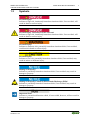
1.3 Symbols
Personal Injury!
Indicates a high-risk, imminently hazardous situation which, if not avoided, will
result in death or serious injury.
Personal Injury Caused by Electric Current!
Indicates a high-risk, imminently hazardous situation which, if not avoided, will
result in death or serious injury.
Personal Injury!
Indicates a moderate-risk, potentially hazardous situation which, if not avoided,
could result in death or serious injury.
Personal Injury!
Indicates a low-risk, potentially hazardous situation which, if not avoided, may
result in minor or moderate injury.
Damage to Property!
Indicates a potentially hazardous situation which, if not avoided, may result in
damage to property.
Damage to Property Caused by Electrostatic Discharge (ESD)!
Indicates a potentially hazardous situation which, if not avoided, may result in
damage to property.
Important Note!
Indicates a potential malfunction which, if not avoided, however, will not result in
damage to property.

8 Notes about this Documentation WAGO-I/O-SYSTEM 750
750-652 Serial Interface RS-232 / RS-485
Manual
Version 1.4.0
Additional Information:
Refers to additional information which is not an integral part of this
documentation (e.g., the Internet).

WAGO-I/O-SYSTEM 750 Notes about this Documentation 9
750-652 Serial Interface RS-232 / RS-485
Manual
Version 1.4.0
1.4 Number Notation
Table 2: Number Notation
Number Code
Example
Note
Decimal
100
Normal notation
Hexadecimal
0x64
C notation
Binary
'100'
'0110.0100'
In quotation marks, nibble separated with
dots (.)
1.5 Font Conventions
Table 3: Font Conventions
Font Type
Indicates
italic
Names of paths and data files are marked in italic-type.
e.g.: C:\Program Files\WAGO Software
Menu
Menu items are marked in bold letters.
e.g.: Save
>
A greater-than sign between two names means the selection of a
menu item from a menu.
e.g.: File > New
Input
Designation of input or optional fields are marked in bold letters,
e.g.: Start of measurement range
“Value”
Input or selective values are marked in inverted commas.
e.g.: Enter the value “4 mA” under Start of measurement range.
[Button]
Pushbuttons in dialog boxes are marked with bold letters in square
brackets.
e.g.: [Input]
[Key]
Keys are marked with bold letters in square brackets.
e.g.: [F5]

10 Important Notes WAGO-I/O-SYSTEM 750
750-652 Serial Interface RS-232 / RS-485
Manual
Version 1.4.0
2 Important Notes
This section includes an overall summary of the most important safety
requirements and notes that are mentioned in each individual section. To protect
your health and prevent damage to devices as well, it is imperative to read and
carefully follow the safety guidelines.
2.1 Legal Bases
2.1.1 Subject to Changes
WAGO Kontakttechnik GmbH & Co. KG reserves the right to provide for any
alterations or modifications that serve to increase the efficiency of technical
progress. WAGO Kontakttechnik GmbH & Co. KG owns all rights arising from
the granting of patents or from the legal protection of utility patents. Third-party
products are always mentioned without any reference to patent rights. Thus, the
existence of such rights cannot be excluded.
2.1.2 Personnel Qualifications
All sequences implemented on WAGO-I/O-SYSTEM 750 devices may only be
carried out by electrical specialists with sufficient knowledge in automation. The
specialists must be familiar with the current norms and guidelines for the devices
and automated environments.
All changes to the coupler or controller should always be carried out by qualified
personnel with sufficient skills in PLC programming.
2.1.3 Use of the WAGO-I/O-SYSTEM 750 in Compliance with
Underlying Provisions
Fieldbus couplers, fieldbus controllers and I/O modules found in the modular
WAGO-I/O-SYSTEM 750 receive digital and analog signals from sensors and
transmit them to actuators or higher-level control systems. Using programmable
controllers, the signals can also be (pre-) processed.
The devices have been developed for use in an environment that meets the IP20
protection class criteria. Protection against finger injury and solid impurities up to
12.5 mm diameter is assured; protection against water damage is not ensured.
Unless otherwise specified, operation of the devices in wet and dusty
environments is prohibited.
Operating the WAGO-I/O-SYSTEM 750 devices in home applications without
further measures is only permitted if they meet the emission limits (emissions of
interference) according to EN 61000-6-3. You will find the relevant information
in the section “Device Description” > “Standards and Guidelines” in the manual
for the used fieldbus coupler/controller.

WAGO-I/O-SYSTEM 750 Important Notes 11
750-652 Serial Interface RS-232 / RS-485
Manual
Version 1.4.0
Appropriate housing (per 94/9/EG) is required when operating the WAGO-I/O-
SYSTEM 750 in hazardous environments. Please note that a prototype test
certificate must be obtained that confirms the correct installation of the system in
a housing or switch cabinet.
2.1.4 Technical Condition of Specified Devices
The devices to be supplied ex works are equipped with hardware and software
configurations, which meet the individual application requirements. WAGO
Kontakttechnik GmbH & Co. KG will be exempted from any liability in case of
changes in hardware or software as well as to non-compliant usage of devices.
Please send your request for modified and new hardware or software
configurations directly to WAGO Kontakttechnik GmbH & Co. KG.

12 Important Notes WAGO-I/O-SYSTEM 750
750-652 Serial Interface RS-232 / RS-485
Manual
Version 1.4.0
2.2 Safety Advice (Precautions)
For installing and operating purposes of the relevant device to your system the
following safety precautions shall be observed:
Do not work on devices while energized!
All power sources to the device shall be switched off prior to performing any
installation, repair or maintenance work.
Install the device only in appropriate housings, cabinets or in electrical
operation rooms!
The WAGO-I/O-SYSTEM 750 and its components are an open system. As such,
install the system and its components exclusively in appropriate housings,
cabinets or in electrical operation rooms. Allow access to such equipment and
fixtures to authorized, qualified staff only by means of specific keys or tools.
Replace defective or damaged devices!
Replace defective or damaged device/module (e.g., in the event of deformed
contacts), since the long-term functionality of device/module involved can no
longer be ensured.
Protect the components against materials having seeping and insulating
properties!
The components are not resistant to materials having seeping and insulating
properties such as: aerosols, silicones and triglycerides (found in some hand
creams). If you cannot exclude that such materials will appear in the component
environment, then install the components in an enclosure being resistant to the
above-mentioned materials. Clean tools and materials are imperative for handling
devices/modules.
Clean only with permitted materials!
Clean soiled contacts using oil-free compressed air or with ethyl alcohol and
leather cloths.

WAGO-I/O-SYSTEM 750 Important Notes 13
750-652 Serial Interface RS-232 / RS-485
Manual
Version 1.4.0
Do not use any contact spray!
Do not use any contact spray. The spray may impair contact area functionality in
connection with contamination.
Do not reverse the polarity of connection lines!
Avoid reverse polarity of data and power supply lines, as this may damage the
devices involved.
Avoid electrostatic discharge!
The devices are equipped with electronic components that may be destroyed by
electrostatic discharge when touched. Please observe the safety precautions
against electrostatic discharge per DIN EN 61340-5-1/-3. When handling the
devices, please ensure that environmental factors (personnel, work space and
packaging) are properly grounded.

14 Device Description WAGO-I/O-SYSTEM 750
750-652 Serial Interface RS-232 / RS-485
Manual
Version 1.4.0
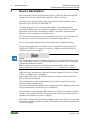
3 Device Description
The I/O module 750-652 (Serial Interface RS-232 / RS-485) allows the optional
connection of devices with a RS-485, RS-422 or RS-232 interface.
It also provides gateways between the serial interface and the fieldbus systems
supported by the WAGO-I/O-SYSTEM 750.
No higher protocol level is required by the module. Communication to the
associated fieldbus master is completely transparent. This provides for a broader
application scope for the serial interface module. If required, communication
protocols can be configured via fieldbus master.
The 2560 byte input buffer provides for high data baud rates. At lower baud rates,
the data received in lower priority tasks is evaluated without data loss.
The 512-byte output buffer provides fast transmission of larger data strings.
The operating mode of the I/O module can be configured with the start-up tool
WAGO-I/O-CHECK 3.3 (firmware version 03 or higher requires WAGO-I/O-
CHECK version 3.5.3 or higher).
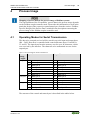
NOTE
The default operating mode is RS-485 half-duplex. The default data transmission
rate is 9600 baud. 1 start bit, 8 data bits and 1 stop bit are sent. There is no parity
generation and dataflow control.
Before starting operation, the connections of the I/O module must be cabled
appropriately (see section “Connect Devices” > … > “Connection Examples” ).
In RS-232 mode, the interface works in accordance with the TIA/EIA-232-F and
CCITT V.28/DIN 66259-1 standards.
In RS-485/RS-422 mode, the interface works in accordance with the TIA/EIA-
485-A, DIN 66259 standards.
The connected device can communicate directly with the control unit via the
fieldbus coupler/controller used.
The active communication channel works independent of the fieldbus system used
in full or half-duplex operation at up to 115200 baud.
In the data flow control through RTS/CTS in RS-232 mode, a lead time or follow-
on time can be configured for the I/O module for the RTS signal. This function is
available with firmware version 03 or higher.
Direct data exchange between different fieldbus nodes of the 750 series is possible
in conjunction with a second I/O module. This function is available with firmware
version 03 or higher.

WAGO-I/O-SYSTEM 750 Device Description 15
750-652 Serial Interface RS-232 / RS-485
Manual
Version 1.4.0
The I/O module can be configured as a DMX sender with a baud rate of
250 kBits/s. This function is available with firmware version 03 or higher.
The wiring to the communication partner takes place in RS-232 mode via the
TxD, RxD connections, if necessary RTS/CTS and ground and in the RS-485/
RS-422 mode via the connections A, B, X, Y, and ground.
The shield connection is fed directly to the carrier rail and contact is made
automatically by snapping the module onto the rail.
The assignment of the connections is described in the “Connectors” section.
Connection examples are shown in section “Connecting Devices” > … >
“Connection Example(s)”.
Multi-color LEDs indicate the operating status and the trouble-free internal bus
communication as well as the status of the signal transmission.
The meaning of the LEDs is described in the “Display Elements” section.
The I/O module 750-652 (Serial Interface RS-232 / RS-485) receives the 24 V
voltage supply for the field level from an upstream I/O module or from the
fieldbus coupler/controller via blade-formed power jumper contacts. It then
provides these potentials to subsequent I/O modules via spring-formed power
jumper contacts.
The field voltage and the system voltage are electrically isolated from each other.
With consideration of the power jumper contacts, the individual modules can be
arranged in any combination when configuring the fieldbus node. An arrangement
in groups within the group of potentials is not necessary.

16 Device Description WAGO-I/O-SYSTEM 750
750-652 Serial Interface RS-232 / RS-485
Manual
Version 1.4.0
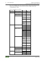
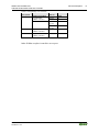
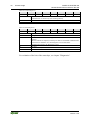
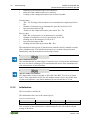
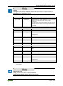
The 750-652 module can be used with the fieldbus couplers and controllers of the
WAGO-I/O-SYSTEM 750 of the specified version or higher listed in the
“Compatibility list” table.
Table 4: Compatibility List 750-0652
Bus System
Fieldbus
couplers/controllers
Item No.
Firmware
status
PROFINET
Fieldbus couplers
750-370
02
Profibus
Fieldbus couplers
750-333
14
Programmable
fieldbus controller
750-833
14
I/O-IPC
*
758-870/
000-111
05
758-870/
000-131
05
758-874/
000-111
05
758-875/
000-111
05
758-876/
000-111
05
ETHERNET
Fieldbus couplers
750-341
07
750-342
17
750-352
02
Programmable
fieldbus controller
750-841
18
750-842
18
750-843
02
750-871
07
750-872
03
750-873
03
750-880
02
750-881
02
750-882
01
I/O-IPC
758-870/
000-110
05
758-870/
000-130
05
758-874/
000-110
05
758-875/
000-110
05
758-875/
000-130
05
758-876/
000-110
05
DeviceNet
Fieldbus couplers
750-306
4K
ECO fieldbus coupler
750-346
10
Programmable
fieldbus controller
750-806
10
CANopen
Fieldbus couplers
750-337
19
750-338
19
ECO fieldbus coupler
750-347
08
750-348
08

WAGO-I/O-SYSTEM 750 Device Description 17
750-652 Serial Interface RS-232 / RS-485
Manual
Version 1.4.0
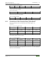
Table 4: Compatibility List 750-0652
Bus System
Fieldbus
couplers/controllers
Item No.
Firmware
status
Programmable
fieldbus controller
750-837
14
750-838
14
I/O-IPC
*
758-870/
000-112
05
758-875/
000-112
05
KNX
Programmable
fieldbus controller
750-849
04
BACnet
Programmable
fieldbus controller
750-830
03
*
Also available via 2 ETHERNET interfaces
Other fieldbus couplers/controllers on request.

18 Device Description WAGO-I/O-SYSTEM 750
750-652 Serial Interface RS-232 / RS-485
Manual
Version 1.4.0
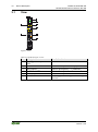
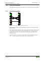
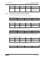
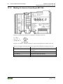
3.1 View
Figure 1: View
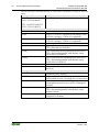
Table 5: Legend for Figure “View”
Pos.
Description
Details See Section
1
Marking possibility with Mini-
WSB
---
2
Status LEDs
“Device Description” > “Display Elements”
3
Data contacts
“Device Description” > “Connectors”
4
CAGE CLAMP
®
connectors
“Device Description” > “Connectors”
5
Power jumper contacts
“Device Description” > “Connectors”
6
Release tab
“Mounting” > “Inserting and Removing
Devices”

WAGO-I/O-SYSTEM 750 Device Description 19
750-652 Serial Interface RS-232 / RS-485
Manual
Version 1.4.0
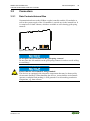
3.2 Connectors
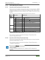
3.2.1 Data Contacts/Internal Bus
Communication between the fieldbus coupler/controller and the I/O modules as
well as the system supply of the I/O modules is carried out via the internal bus. It
is comprised of 6 data contacts, which are available as self-cleaning gold spring
contacts.
Figure 2: Data Contacts
Do not place the I/O modules on the gold spring contacts!
Do not place the I/O modules on the gold spring contacts in order to avoid soiling
or scratching!
Ensure that the environment is well grounded!
The devices are equipped with electronic components that may be destroyed by
electrostatic discharge. When handling the devices, ensure that the environment
(persons, workplace and packing) is well grounded. Avoid touching conductive
components, e.g. data contacts.

20 Device Description WAGO-I/O-SYSTEM 750
750-652 Serial Interface RS-232 / RS-485
Manual
Version 1.4.0
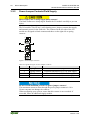
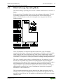
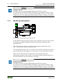
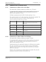
3.2.2 Power Jumper Contacts/Field Supply
Risk of injury due to sharp-edged blade contacts!
The blade contacts are sharp-edged. Handle the I/O module carefully to prevent
injury.
The I/O module 750-652 has 2 self-cleaning power jumper contacts that supply
and transmit power for the field side. The contacts on the left side of the I/O
module are designed as blade contacts and those on the right side as spring
contacts.
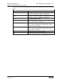
Figure 3: Power Jumper Contacts
Table 6: Legend for Figure “Power Jumper Contacts”
Contact
Type
Function
1
Spring contact
Potential transmission (U
v
) for field supply
2
Spring contact
Potential transmission (0 V) for field supply
3
Blade contact
Potential feed-in (0 V) for field supply
4
Blade contact
Potential feed-in (U
v
) for field supply
Do not exceed maximum current via power jumper contacts!
The maximum current to flow through the power jumper contacts is 10 A.
Greater currents can damage the contacts.
When configuring your system, ensure that this current is not exceeded. If
exceeded, insert an additional supply module.
Page is loading ...
Page is loading ...
Page is loading ...
Page is loading ...
Page is loading ...
Page is loading ...
Page is loading ...
Page is loading ...
Page is loading ...
Page is loading ...
Page is loading ...
Page is loading ...
Page is loading ...
Page is loading ...
Page is loading ...
Page is loading ...
Page is loading ...
Page is loading ...
Page is loading ...
Page is loading ...
Page is loading ...
Page is loading ...
Page is loading ...
Page is loading ...
Page is loading ...
Page is loading ...
Page is loading ...
Page is loading ...
Page is loading ...
Page is loading ...
Page is loading ...
Page is loading ...
Page is loading ...
Page is loading ...
Page is loading ...
Page is loading ...
Page is loading ...
Page is loading ...
Page is loading ...
Page is loading ...
Page is loading ...
Page is loading ...
Page is loading ...
Page is loading ...
Page is loading ...
Page is loading ...
Page is loading ...
Page is loading ...
Page is loading ...
Page is loading ...
Page is loading ...
Page is loading ...
Page is loading ...
Page is loading ...
Page is loading ...
Page is loading ...
Page is loading ...
Page is loading ...
Page is loading ...
Page is loading ...
Page is loading ...
Page is loading ...
-
 1
1
-
 2
2
-
 3
3
-
 4
4
-
 5
5
-
 6
6
-
 7
7
-
 8
8
-
 9
9
-
 10
10
-
 11
11
-
 12
12
-
 13
13
-
 14
14
-
 15
15
-
 16
16
-
 17
17
-
 18
18
-
 19
19
-
 20
20
-
 21
21
-
 22
22
-
 23
23
-
 24
24
-
 25
25
-
 26
26
-
 27
27
-
 28
28
-
 29
29
-
 30
30
-
 31
31
-
 32
32
-
 33
33
-
 34
34
-
 35
35
-
 36
36
-
 37
37
-
 38
38
-
 39
39
-
 40
40
-
 41
41
-
 42
42
-
 43
43
-
 44
44
-
 45
45
-
 46
46
-
 47
47
-
 48
48
-
 49
49
-
 50
50
-
 51
51
-
 52
52
-
 53
53
-
 54
54
-
 55
55
-
 56
56
-
 57
57
-
 58
58
-
 59
59
-
 60
60
-
 61
61
-
 62
62
-
 63
63
-
 64
64
-
 65
65
-
 66
66
-
 67
67
-
 68
68
-
 69
69
-
 70
70
-
 71
71
-
 72
72
-
 73
73
-
 74
74
-
 75
75
-
 76
76
-
 77
77
-
 78
78
-
 79
79
-
 80
80
-
 81
81
-
 82
82


WAGO 750-468 User manual
- Category
- Stroboscopes & disco lights
- Type
- User manual
- This manual is also suitable for
Ask a question and I''ll find the answer in the document
Finding information in a document is now easier with AI
Related papers
-
WAGO I/O-SYSTEM 750 Technical Description, Installation And Configuration
-
WAGO 24VDC 1.0A Ex i power supply User manual
-
-
Sharp DP-750 User manual
-
Sharp I/O SYSTEM 750 750-833 User manual
-
-
-
-
-
Other documents
-
ICP DAS USA I-7550 User manual
-
Helmholz 700-158-3DP02 User guide
-
PXM PxDesigner User manual
-
Belden Hirschmann OZD Profi G12DE ATEX 1 User manual
-
 Deprag AST11-2 Operating Instruction Booklet
-
 SEPTENTRIO AsteRx-i3 S Pro Plus GNSS/INS Receiver Installation guide
-
ABB AWT210 User manual
-
 Hexin Technology HXJZ-881 User manual
-
turck PROFINET Controller/Device Commissioning in CODESYS 3 Getting Started
-
RADWAG IM01.EX-4 User manual


