WAGO 24VDC 1.0A Ex i power supply User manual
- Type
- User manual

Manual
WAGO-I/O-SYSTEM 750
750-606
24 V DC 1.0 A power supply Ex i
Supply
Module 24 V DC, 1.0 A Ex i
Version 1.4.0 valid from HW version 03

2 WAGO-I/O-SYSTEM 750
750-606 24 V DC 1.0 A power supply Ex i
Manual
Version 1.4.0 valid from HW version 03
© 2017 WAGO Kontakttechnik GmbH & Co. KG
All rights reserved.
WAGO Kontakttechnik GmbH & Co. KG
Hansastraße 27
D-32423 Minden
Phone: +49 (0) 571/8 87 – 0
Fax: +49 (0) 571/8 87 – 1 69
Web: http://www.wago.com
Technical Support
Phone: +49 (0) 571/8 87 – 5 55
Fax: +49 (0) 571/8 87 – 85 55
Every conceivable measure has been taken to ensure the accuracy and
completeness of this documentation. However, as errors can never be fully
excluded, we always appreciate any information or suggestions for improving the
documentation.
We wish to point out that the software and hardware terms as well as the
trademarks of companies used and/or mentioned in the present manual are
generally protected by trademark or patent.
WAGO is a registered trademark of WAGO Verwaltungsgesellschaft mbH.

WAGO-I/O-SYSTEM 750 Table of Contents 3
750-606 24 V DC 1.0 A power supply Ex i
Manual
Version 1.4.0 valid from HW version 03
Table of Contents
1 Notes about this Documentation ............................................................. 5
1.1 Validity of this Documentation................................................................. 5
1.2 Copyright ................................................................................................ 5
1.3 Symbols ................................................................................................. 6
1.4 Number Notation .................................................................................... 8
1.5 Font Conventions ................................................................................... 8
2 Important Notes ........................................................................................ 9
2.1 Legal Bases ............................................................................................ 9
2.1.1 Subject to Changes ............................................................................ 9
2.1.2 Personnel Qualifications .................................................................... 9
2.1.3 Use of the WAGO-I/O-SYSTEM 750 in Compliance with Underlying
Provisions .......................................................................................... 9
2.1.4 Technical Condition of Specified Devices......................................... 10
2.2 Safety Advice (Precautions) ................................................................. 11
3 Device Description .................................................................................. 13
3.1 View ..................................................................................................... 16
3.2 Connectors ........................................................................................... 17
3.2.1 Data Contacts/Internal Bus .............................................................. 17
3.2.2 Power Jumper Contacts/Field Supply .............................................. 18
3.2.3 CAGE CLAMP
®
Connectors ............................................................. 19
3.3 Display Elements .................................................................................. 20
3.4 Operating Elements .............................................................................. 20
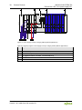
3.5 Schematic Diagram .............................................................................. 21
3.6 Technical Data ..................................................................................... 22
3.6.1 Device Data ..................................................................................... 22
3.6.2 Supply .............................................................................................. 22
3.6.3 Communication ................................................................................ 22
3.6.4 Explosion Protection ........................................................................ 22
3.6.5 Connection Type .............................................................................. 23
3.6.6 Climatic Environmental Conditions ................................................... 23
3.7 Approvals ............................................................................................. 24
3.8 Standards and Guidelines .................................................................... 27
4 Process Image ......................................................................................... 29
5 Mounting .................................................................................................. 30
5.1 Mounting Sequence .............................................................................. 30
5.2 Inserting and Removing Devices .......................................................... 31
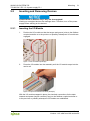
5.2.1 Inserting the I/O Module ................................................................... 31
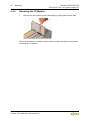
5.2.2 Removing the I/O Module ................................................................ 32
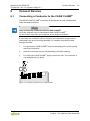
6 Connect Devices ..................................................................................... 33
6.1 Connecting a Conductor to the CAGE CLAMP
®
................................... 33
6.2 Power Supply Concept ......................................................................... 34
6.2.1 Power Supply Concept in Marine Applications ................................. 37
7 Use in Hazardous Environments ........................................................... 39

4 Table of Contents WAGO-I/O-SYSTEM 750
750-606 24 V DC 1.0 A power supply Ex i
Manual
Version 1.4.0 valid from HW version 03
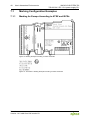
7.1 Marking Configuration Examples .......................................................... 40
7.1.1 Marking for Europe According to ATEX and IECEx .......................... 40
7.1.2 Marking for America (NEC) and Canada (CEC) ............................... 44
7.2 Installation Regulations......................................................................... 47
7.2.1 Special Notes Regarding Explosion Protection ................................ 47
7.2.2 Special Notes Regarding ANSI/ISA Ex ............................................ 49
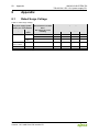
8 Appendix ................................................................................................. 50
8.1 Rated Surge Voltage ............................................................................ 50
List of Figures .................................................................................................. 51
List of Tables .................................................................................................... 52

WAGO-I/O-SYSTEM 750 Notes about this Documentation 5
750-606 24 V DC 1.0 A power supply Ex i
Manual
Version 1.4.0 valid from HW version 03
1 Notes about this Documentation
Always retain this documentation!
This documentation is part of the product. Therefore, retain the documentation
during the entire service life of the product. Pass on the documentation to any
subsequent user. In addition, ensure that any supplement to this documentation
is included, if necessary.
1.1 Validity of this Documentation
This documentation is only applicable to the I/O module 750-606
(24 V DC 1.0 A power supply Ex i).
The I/O module 750-606 shall only be installed and operated according to the
instructions in this manual and in the manual for the used fieldbus
coupler/controller.
Consider power layout of the WAGO-I/O-SYSTEM 750!
In addition to these operating instructions, you will also need the manual for the
used fieldbus coupler/controller, which can be downloaded at www.wago.com
.
There, you can obtain important information including information on electrical
isolation, system power and supply specifications.
1.2 Copyright
This Manual, including all figures and illustrations, is copyright-protected. Any
further use of this Manual by third parties that violate pertinent copyright
provisions is prohibited. Reproduction, translation, electronic and phototechnical
filing/archiving (e.g., photocopying) as well as any amendments require the
written consent of WAGO Kontakttechnik GmbH & Co. KG, Minden, Germany.
Non-observance will involve the right to assert damage claims.

6 Notes about this Documentation WAGO-I/O-SYSTEM 750
750-606 24 V DC 1.0 A power supply Ex i
Manual
Version 1.4.0 valid from HW version 03
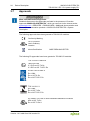
1.3 Symbols
Personal Injury!
Indicates a high-risk, imminently hazardous situation which, if not avoided, will
result in death or serious injury.
Personal Injury Caused by Electric Current!
Indicates a high-risk, imminently hazardous situation which, if not avoided, will
result in death or serious injury.
Personal Injury!
Indicates a moderate-risk, potentially hazardous situation which, if not avoided,
could result in death or serious injury.
Personal Injury!
Indicates a low-risk, potentially hazardous situation which, if not avoided, may
result in minor or moderate injury.
Damage to Property!
Indicates a potentially hazardous situation which, if not avoided, may result in
damage to property.
Damage to Property Caused by Electrostatic Discharge (ESD)!
Indicates a potentially hazardous situation which, if not avoided, may result in
damage to property.
Important Note!
Indicates a potential malfunction which, if not avoided, however, will not result in
damage to property.

WAGO-I/O-SYSTEM 750 Notes about this Documentation 7
750-606 24 V DC 1.0 A power supply Ex i
Manual
Version 1.4.0 valid from HW version 03
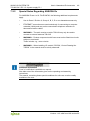
Additional Information:
Refers to additional information which is not an integral part of this
documentation (e.g., the Internet).

8 Notes about this Documentation WAGO-I/O-SYSTEM 750
750-606 24 V DC 1.0 A power supply Ex i
Manual
Version 1.4.0 valid from HW version 03
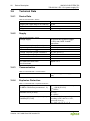
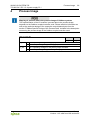
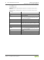
1.4 Number Notation
Table 1: Number Notation
Number Code
Example
Note
Decimal
100
Normal notation
Hexadecimal
0x64
C notation
Binary
'100'
'0110.0100'
In quotation marks, nibble separated
with dots (.)
1.5 Font Conventions
Table 2: Font Conventions
Font Type
Indicates
italic
Names of paths and data files are marked in italic-type.
e.g.: C:\Program Files\WAGO Software
Menu
Menu items are marked in bold letters.
e.g.:
Save
>
A greater-than sign between two names means the selection of a
menu item from a menu.
e.g.: File > New
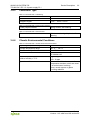
Input
Designation of input or optional fields are marked in bold letters,
e.g.: Start of measurement range
“Value”
Input or selective values are marked in inverted commas.
e.g.: Enter the value “4 mA” under
Start of measurement range
.
[Button]
Pushbuttons in dialog boxes are marked with bold letters in square
brackets.
e.g.: [Input]
[Key]
Keys are marked with bold letters in square brackets.
e.g.: [F5]

WAGO-I/O-SYSTEM 750 Important Notes 9
750-606 24 V DC 1.0 A power supply Ex i
Manual
Version 1.4.0 valid from HW version 03
2 Important Notes
This section includes an overall summary of the most important safety
requirements and notes that are mentioned in each individual section. To protect
your health and prevent damage to devices as well, it is imperative to read and
carefully follow the safety guidelines.
2.1 Legal Bases
2.1.1 Subject to Changes
WAGO Kontakttechnik GmbH & Co. KG reserves the right to provide for any
alterations or modifications. WAGO Kontakttechnik GmbH & Co. KG owns all
rights arising from the granting of patents or from the legal protection of utility
patents. Third-party products are always mentioned without any reference to
patent rights. Thus, the existence of such rights cannot be excluded.
2.1.2 Personnel Qualifications
All sequences implemented on WAGO-I/O-SYSTEM 750 devices may only be
carried out by electrical specialists with sufficient knowledge in automation. The
specialists must be familiar with the current norms and guidelines for the devices
and automated environments.
All changes to the coupler or controller should always be carried out by qualified
personnel with sufficient skills in PLC programming.
2.1.3 Use of the WAGO-I/O-SYSTEM 750 in Compliance with
Underlying Provisions
Fieldbus couplers, fieldbus controllers and I/O modules found in the modular
WAGO-I/O-SYSTEM 750 receive digital and analog signals from sensors and
transmit them to actuators or higher-level control systems. Using programmable
controllers, the signals can also be (pre-) processed.
The devices have been developed for use in an environment that meets the IP20
protection class criteria. Protection against finger injury and solid impurities up to
12.5 mm diameter is assured; protection against water damage is not ensured.
Unless otherwise specified, operation of the devices in wet and dusty
environments is prohibited.
Operating the WAGO-I/O-SYSTEM 750 devices in home applications without
further measures is only permitted if they meet the emission limits (emissions of
interference) according to EN 61000-6-3. You will find the relevant information in
the section “Device Description” > “Standards and Guidelines” in the manual for
the used fieldbus coupler/controller.
Appropriate housing (per 2014/34/EU) is required when operating the WAGO-
I/O-SYSTEM 750 in hazardous environments. Please note that a prototype test

10 Important Notes WAGO-I/O-SYSTEM 750
750-606 24 V DC 1.0 A power supply Ex i
Manual
Version 1.4.0 valid from HW version 03
certificate must be obtained that confirms the correct installation of the system in
a housing or switch cabinet.
2.1.4 Technical Condition of Specified Devices
The devices to be supplied ex works are equipped with hardware and software
configurations, which meet the individual application requirements. WAGO
Kontakttechnik GmbH & Co. KG will be exempted from any liability in case of
changes in hardware or software as well as to non-compliant usage of devices.
Please send your request for modified and new hardware or software
configurations directly to WAGO Kontakttechnik GmbH & Co. KG.

WAGO-I/O-SYSTEM 750 Important Notes 11
750-606 24 V DC 1.0 A power supply Ex i
Manual
Version 1.4.0 valid from HW version 03
2.2 Safety Advice (Precautions)
For installing and operating purposes of the relevant device to your system the
following safety precautions shall be observed:
Do not work on devices while energized!
All power sources to the device shall be switched off prior to performing any
installation, repair or maintenance work.
Install the device only in appropriate housings, cabinets or in electrical
operation rooms!
The WAGO-I/O-SYSTEM 750 and its components are an open system. As such,
install the system and its components exclusively in appropriate housings,
cabinets or in electrical operation rooms. Allow access to such equipment and
fixtures to authorized, qualified staff only by means of specific keys or tools.
Replace defective or damaged devices!
Replace defective or damaged device/module (e.g., in the event of deformed
contacts), since the long-term functionality of device/module involved can no
longer be ensured.
Protect the components against materials having seeping and insulating
properties!
The components are not resistant to materials having seeping and insulating
properties such as: aerosols, silicones and triglycerides (found in some hand
creams). If you cannot exclude that such materials will appear in the component
environment, then install the components in an enclosure being resistant to the
above-mentioned materials. Clean tools and materials are imperative for
handling devices/modules.
Clean only with permitted materials!
Clean soiled contacts using oil-free compressed air or with ethyl alcohol and
leather cloths.

12 Important Notes WAGO-I/O-SYSTEM 750
750-606 24 V DC 1.0 A power supply Ex i
Manual
Version 1.4.0 valid from HW version 03
Do not use any contact spray!
Do not use any contact spray. The spray may impair contact area functionality in
connection with contamination.
Do not reverse the polarity of connection lines!
Avoid reverse polarity of data and power supply lines, as this may damage the
devices involved.
Avoid electrostatic discharge!
The devices are equipped with electronic components that may be destroyed by
electrostatic discharge when touched. Please observe the safety precautions
against electrostatic discharge per DIN EN 61340-5-1/-3. When handling the
devices, please ensure that environmental factors (personnel, work space and
packaging) are properly grounded.

WAGO-I/O-SYSTEM 750 Device Description 13
750-606 24 V DC 1.0 A power supply Ex i
Manual
Version 1.4.0 valid from HW version 03
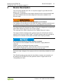
3 Device Description
The I/O module 750-606 (24 V DC 1.0 A power supply Ex i) provides 24 VDC
power to the 750 Series.
Furthermore, it separates the intrinsically safe part from the non-intrinsically safe
part of the fieldbus node and makes diagnostic information available in the
process image.
Installation only in zone 2 or in non-hazardous environments!
The installation of the WAGO-I/O-SYSTEM 750 fieldbus couplers/controllers and
I/O modules is only to be done in zone 2 or in non-hazardous environments.
One green status LED indicates the status of the input voltage and one green/red
status LED indicates the status of the output voltage.
The meaning of the LEDs is described in the “Display Elements” section.
The supply module receives the 24 V voltage supply for the field level from an
external source via the CAGE CLAMP
®
connectors and provides this potential to
subsequent I/O modules via the power contacts used as spring contacts.
Do not exceed maximum current via power contacts!
The maximum current available from the 750-606 Ex-i Supply Module is
1000 mA.
Greater currents can damage the power contacts.
When configuring the system, ensure that this current is not exceeded.
If exceeded, an additional potential feed module must be used.
Input and output voltages of the supply module are electrically isolated from each
other.
The 750-606 module can be used with the fieldbus couplers and controllers of
the WAGO-I/O-SYSTEM 750 of the specified version or higher listed in the
“Compatibility list” table.

14 Device Description WAGO-I/O-SYSTEM 750
750-606 24 V DC 1.0 A power supply Ex i
Manual
Version 1.4.0 valid from HW version 03
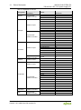
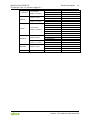
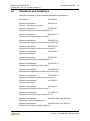
Table 3: Compatibility list 750-606
Bus System
Fieldbus Couplers/
Controllers
Item No.
Software –
Version No.
BACnet
Programmable
Fieldbus Controllers
750-829
07
750-830
04
750-831
01
CANopen
Fieldbus Coupler
750-337
19
750-337/025-000
19
750-338
19
750-338/000-500
19
750-338/200-000
19
750-347
08
750-348
08
Programmable
Fieldbus Controllers
750-837
14
750-837/020-000
14
750-837/021-000
14
750-838
14
750-838/020-000
14
750-838/021-000
14
DeviceNet
Fieldbus Coupler
750-306
4K
750-306/000-001
4K
750-306/000-002
4K
750-306/000-003
W7
750-306/000-004
4K
750-306/000-005
4K
750-306/000-006
4K
750-346
10
Programmable
Fieldbus Controllers
750-806 10
EtherCat Fieldbus Coupler
750-354
02
750-354/000-001
02
ETHERNET
Fieldbus Coupler
750-341
07
750-352
02
750-352/000-001
02
Programmable
Fieldbus Controllers
750-841
18
750-841/025-000
18
750-842
17
750-842/000-101
17
750-843
02
750-852
01
750-871
07
750-873
03
750-880
01
750-881
02
750-882
01
750-885
04
Telecontrol
Programmable
Fieldbus Controllers
750-872
03
750-872/020-000
02
KNX
Programmable
Fieldbus Controllers
750-849
04*
750-889
05

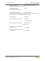
WAGO-I/O-SYSTEM 750 Device Description 15
750-606 24 V DC 1.0 A power supply Ex i
Manual
Version 1.4.0 valid from HW version 03
LonWorks
®
Programmable
Fieldbus Controllers
750-819
09
750-819/005-000
09
750-819/009-000
09
MODBUS
Fieldbus Coupler
750-315/300-000
01
750-316/300-000
01
Programmable
Fieldbus Controllers
750-815/300-000
01
750-816/300-000
01
PFC200
Programmable
Fieldbus Controllers
750-8202
01
750-8202/025-001
01
750-8202/025-002
02
750-8203
01
750-8204
01
750-8206
01
PROFIBUS
Fieldbus Coupler
750-333
14
750-333/007-000
14
750-333/025-000
14
Programmable
Fieldbus Controllers
750-833
14
750-833/025-000
14
PROFINET
Fieldbus Coupler
750-340
03
750-370
02
750-375
01
sercos
Fieldbus Coupler
750-351
04
* Limited functionality

16 Device Description WAGO-I/O-SYSTEM 750
750-606 24 V DC 1.0 A power supply Ex i
Manual
Version 1.4.0 valid from HW version 03
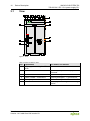
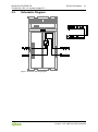
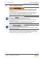
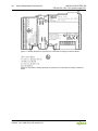
3.1 View
Figure 1: View
</dg_
Table 4:Legend for Figure “View”
No.
Explanation
For details, see Section
1
Marking options using the Mini-
WSB
---
2
Status LEDs
“Device Description” > “Display
Elements”
3
Data contacts
“Device Description” > “Connections”
4
CAGE CLAMP
®
connections
“Device Description” > “Connections”
5
Power jumper contacts
"Device Description" > "Connections"
6
Latches
"Mounting" > "Inserting and Removing
Device"

WAGO-I/O-SYSTEM 750 Device Description 17
750-606 24 V DC 1.0 A power supply Ex i
Manual
Version 1.4.0 valid from HW version 03
3.2 Connectors
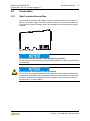
3.2.1 Data Contacts/Internal Bus
Communication between the fieldbus coupler/controller and the I/O modules as
well as the system supply of the I/O modules is carried out via the internal bus. It
is comprised of 6 data contacts, which are available as self-cleaning gold spring
contacts.
Figure 2: Data Contacts
Do not place the I/O modules on the gold spring contacts!
Do not place the I/O modules on the gold spring contacts in order to avoid soiling
or scratching!
Ensure that the environment is well grounded!
The devices are equipped with electronic components that may be destroyed by
electrostatic discharge. When handling the devices, ensure that the environment
(persons, workplace and packing) is well grounded. Avoid touching conductive
components, e.g. data contacts.

18 Device Description WAGO-I/O-SYSTEM 750
750-606 24 V DC 1.0 A power supply Ex i
Manual
Version 1.4.0 valid from HW version 03
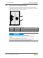
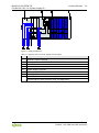
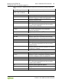
3.2.2 Power Jumper Contacts/Field Supply
The power supply module 750-606 has 2 self-cleaning power jumper contacts
that transmit power for the field side. The contacts on the right side of the power
supply module are designed as spring contacts.
Figure 3: Power Jumper Contacts
Table 5: Legend for Figure “Power Jumper Contacts”
Contact
Type
Function
1
Spring contact
Potential feed-in (U
o
) for field supply
2
Spring contact
Potential feed-in (0 V) for field supply
Do not exceed maximum current via power contacts!
The maximum current available from the 750-606 Ex-i Supply Module is
1000 mA.
Greater currents can damage the power contacts.
When configuring the system, ensure that this current is not exceeded.
If exceeded, an additional potential feed module must be used.

WAGO-I/O-SYSTEM 750 Device Description 19
750-606 24 V DC 1.0 A power supply Ex i
Manual
Version 1.4.0 valid from HW version 03
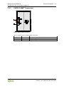
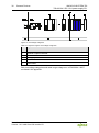
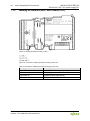
3.2.3 CAGE CLAMP
®
Connectors
Figure 4: CAGE CLAMP
®
Connectors
Table 6: Legend for Figure “CAGE CLAMP
®
Connectors”
Designation
Connector
Function
+24 V
1
Supply voltage 24 V DC (−25 % … +30 %)
0 V
2
Supply voltage 0 V

20 Device Description WAGO-I/O-SYSTEM 750
750-606 24 V DC 1.0 A power supply Ex i
Manual
Version 1.4.0 valid from HW version 03
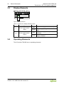
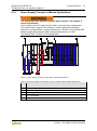
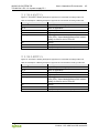
3.3 Display Elements
Figure 5: Display Elements
Table 7: Legend for the “Display Elements” Figure
LED
Designation
State
Function
A
Power supply status –
Input
Off
No power supply at the infeed input
Green
Power supply is applied at the infeed
input.
B
Power supply status –
Output
Red
No power supply at the power jumper
contacts
Green
Power supply applied to the power
jumper contacts.
3.4 Operating Elements
The I/O module 750-606 has no operating elements.
Page is loading ...
Page is loading ...
Page is loading ...
Page is loading ...
Page is loading ...
Page is loading ...
Page is loading ...
Page is loading ...
Page is loading ...
Page is loading ...
Page is loading ...
Page is loading ...
Page is loading ...
Page is loading ...
Page is loading ...
Page is loading ...
Page is loading ...
Page is loading ...
Page is loading ...
Page is loading ...
Page is loading ...
Page is loading ...
Page is loading ...
Page is loading ...
Page is loading ...
Page is loading ...
Page is loading ...
Page is loading ...
Page is loading ...
Page is loading ...
Page is loading ...
Page is loading ...
Page is loading ...
Page is loading ...
-
 1
1
-
 2
2
-
 3
3
-
 4
4
-
 5
5
-
 6
6
-
 7
7
-
 8
8
-
 9
9
-
 10
10
-
 11
11
-
 12
12
-
 13
13
-
 14
14
-
 15
15
-
 16
16
-
 17
17
-
 18
18
-
 19
19
-
 20
20
-
 21
21
-
 22
22
-
 23
23
-
 24
24
-
 25
25
-
 26
26
-
 27
27
-
 28
28
-
 29
29
-
 30
30
-
 31
31
-
 32
32
-
 33
33
-
 34
34
-
 35
35
-
 36
36
-
 37
37
-
 38
38
-
 39
39
-
 40
40
-
 41
41
-
 42
42
-
 43
43
-
 44
44
-
 45
45
-
 46
46
-
 47
47
-
 48
48
-
 49
49
-
 50
50
-
 51
51
-
 52
52
-
 53
53
-
 54
54


WAGO 24VDC 1.0A Ex i power supply User manual
- Type
- User manual
Ask a question and I''ll find the answer in the document
Finding information in a document is now easier with AI
Related papers
-
WAGO 750 series User manual
-
-
-
-
-
-
-
-
-
WAGO I/O-SYSTEM 750 User's Installation And Configuration
Other documents
-
Pepperl+Fuchs HiC2025ES User manual
-
-
SAFATEX SIGMA ATEX User manual
-
-
-
-
Pepperl+Fuchs KCD2-SCD-Ex1 User manual
-
Pepperl+Fuchs KCD0-SD-Ex1.1245.SP User manual
-
-