Page is loading ...
RFS6000 Series RF Switch
Installation Guide
M

MOTOROLA and the Stylized M Logo are registered in the US Patent & Trademark Office.
Symbol is a registered trademark of Symbol Technologies, Inc. All other product or service
names are the property of their respective owners. © Motorola, Inc. 2008. All rights reserved.

1.0 Introduction . . . . . . . . . . . . . . . . . . . . . . . . . . . . . . . . . . . . . . . . . 1
2.0 Specifications . . . . . . . . . . . . . . . . . . . . . . . . . . . . . . . . . . . . . . . 3
3.0 LED Codes . . . . . . . . . . . . . . . . . . . . . . . . . . . . . . . . . . . . . . . . . . . 4
4.0 Hardware Setup. . . . . . . . . . . . . . . . . . . . . . . . . . . . . . . . . . . . . 11
5.0 Regulatory Information . . . . . . . . . . . . . . . . . . . . . . . . . . . . . . . 20
6.0 Part Numbers, Support, and Sales . . . . . . . . . . . . . . . . . . . . . 24
7.0 End-User License Agreement . . . . . . . . . . . . . . . . . . . . . . . . . 25
Contents

4

Introduction
1
1 Introduction
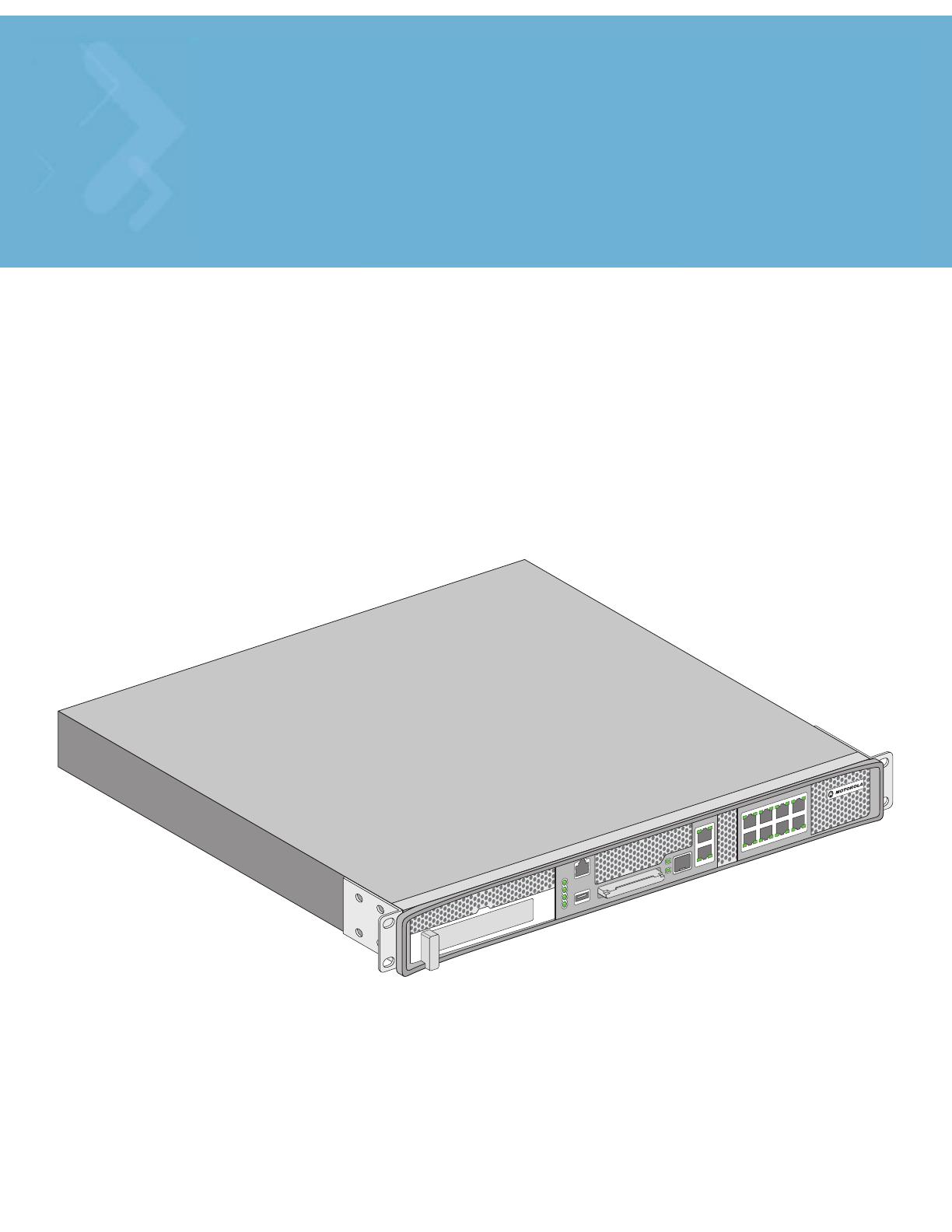
The Motorola RFS6000 Series RF Switch is a high-performance member of Motorola’s Wireless
Switch family. The RFS6000 Series RF Switch provides centralized Wireless LAN (WLAN)
configuration and management by coalescing a network “intelligence” previously spread across
physically distributed access points. By replacing access points with simpler access ports (or “thin”
access points), the RFS6000 Series RF Switch becomes a WLAN’s single point of contact, thus
reducing wireless networking complexity by moving management out of the ceiling and into the
wiring closet. In addition, through the use of patented Virtual AP architecture, the RFS6000 Series
RF Switch lets you create multiple WLANs without changing or adding to the existing wired network
infrastructure.
This document is written for the network device installer.
1.1 Package Contents
Inspect the package contents and report any missing or damaged items to your sales representative.
The package should contain the following:
• RFS6010 RF Switch with Rack Brackets installed
• Console Cable
• Installation Guide (this document)
• China RoHS compliance document
1.2 Document Conventions
The following graphical alerts are used in this document to indicate notable situations:
NOTE Tips, hints, or special requirements that you should take note of.
CAUTION Care is required. Disregarding a caution can result in data loss or
equipment malfunction.
WARNING! Indicates a condition or procedure that could result in personal injury or
equipment damage.
!

Introduction
2
1.3 Warnings
• Read all installation instructions and site survey reports, and verify correct equipment installation before connecting
the system to its power source.
• Remove jewelry and watches before installing this equipment.
• Install the equipment in a rack with adequate dimensions and weight allowances.
• Verify the rack is anchored and cannot tip over or break away from its mountings.
• Verify the unit is grounded before connecting it to the power source.
• Verify any device connected to this unit is properly wired and grounded.
• Connect all power cords to a properly wired and grounded electrical circuit.
• Verify the electrical circuits have appropriate overload protection.
• Attach only approved power cords to the device.
• Motorola strongly recommends the use of an Uninterruptible Power Supply (UPS) that supports the RFS6000 Series
RF Switch power rating. Not using a UPS can result in data loss or equipment damage due to a power surge or power
failure.
• Verify that the power connector and socket are accessible at all times during the operation of the equipment.
• Do not work with power circuits in dimly lit spaces.
• Do not install this equipment or work with its power circuits during thunderstorms or other weather conditions that
could cause a power surge.
• Verify there is adequate ventilation around the device, and ambient temperatures meet equipment operation
specifications.
1.4 Site Preparation
• Consult your site survey and network analysis reports to determine specific equipment placement, port capacity,
power drops, and so on.
• Assign installation responsibility to the appropriate personnel.
• Identify where all installed components are located.
• Verify appropriate rack mounting requirements.
• Provide a sufficient number of power drops for your equipment.
• Ensure adequate, dust-free ventilation to all installed equipment.
• Identify and prepare Ethernet and console port connections.
• Verify that cable lengths are within the maximum allowable distances for optimal signal transmission.
• Verify that the RFS6000 Series RF Switch is powered through an Uninterruptible Power Supply (UPS).

Specifications
3
2 Specifications
2.1 Physical Specifications
2.2 Power Cord Specifications
A power cord is not supplied with the switch. Use only a correctly rated power cord certified (as
appropriate) for the country of operation
.
2.2.1 Power Protection
• If possible, use a circuit dedicated to data processing equipment. Commercial electrical
contractors are familiar with wiring for data processing equipment and can help with the load
balancing of these circuits.
• Install surge protection. Be sure to use a surge protection device between the electricity
source and the RFS6000 Series RF Switch.
• Install an Uninterruptible Power Supply (UPS). A UPS provides continuous power during a
power outage. Some UPS devices have integral surge protection. UPS equipment requires
periodic maintenance to ensure reliability. A UPS of the proper capacity for the data processing
equipment must be purchased.
Width 440mm (17.32 in)
Height 44.45mm (1.75 in)
Depth 390.8mm (15.38 in)
Weight 6.35 Kg (14.0 lbs)
Operating Temperature 0°C - 40°C
Operating Humidity 5% - 85% RH, non-condensing
Operating Altitude 3 km (10000 ft)

LED Codes
4
3 LED Codes
The RFS6010 RF Switch has four vertically-stacked LEDs on its front panel. Each of the switch’s
Gigabit Ethernet ports have two status LEDs. These LEDs display two colors (green & amber), and
three lit states (solid, blinking, and off). The following tables decode the combinations of LED colors
and states for the System Status LEDs and the Gigabit Ethernet LEDs.
3.1 System Status LEDs
System Status 1
Fan status
Temperature status
System Status 2
LED Codes
5
3.1.1 Start Up / POST (Primary System or Redundant System)
3.1.2 Switch Status (Primary System)
3.1.3 Switch Status (Redundant System)
System Status 1 LED System Status 2 LED Event
Off Off Power off
Green Blinking Green Blinking Power On Self Test (POST) running
Green Solid Green Blinking POST succeeded (Operating System Loading)
Green Solid Off POST succeeded (Normal Operation)
Amber Blinking Off POST Failure
Alternating Green Blinking
& Amber Blinking
Alternating Green Blinking
& Amber Blinking
Boot Up Error: Device has an invalid checksum
NOTE During switch start up, the Temperature status LED will be lit Solid
Amber. This is normal behavior and does not indicate an error. At the
completion of start up the Temperature Status LED will switch to Solid
Green.
System Status 1 LED System Status 2 LED Event
Off Off Power off
Green Solid Off No Redundancy Feature Enabled
Green Solid Green Solid
Redundancy Feature Enabled
Actively Adopting Access Ports
Green Solid Amber Blinking
No License to adopt Access Ports
or
No Country Code configured on the switch
or
License and Country Code configured, but no
APs adopted
System Status 1 LED System Status 2 LED Event
Off Off Power off
Green Solid Off No Redundancy Feature Enabled
LED Codes
6
3.1.4 Fan LED
3.1.5 Temperature Status LED
Green Blinking Green Solid
Redundant System failed over and adopting
ports
Green Blinking
Alternating Green Blinking
& Amber Blinking
Redundant System not failed over.
Green Solid Amber Blinking
No License to adopt Access Ports
or
No Country Code configured on the switch
or
License and Country Code configured, but no
APs adopted
Fan LED Event
Off System Off / POST Start
Green Blinking POST in Process
Green Solid All System Fans Normal Operation
Amber Solid
Redundant Cooling Failure
System Operational
Amber Blinking
System Cooling Failure
System will be held in reset until the issue is
resolved
Temperature LED Event
Off System Off
Green Solid
Ambient Inlet Temperature is within specified
operating limit
Amber Solid
Ambient Inlet Temperature is near the maximum
operating temperature
During switch start up this LED will be lit Solid
Amber. This is normal behavior and does not
indicate an error.
System Status 1 LED System Status 2 LED Event

LED Codes
7
Amber Blinking
Ambient Inlet Temperature is above the
maximum specified operating temperature
System will be held in reset until the issue is
resolved
Temperature LED Event

LED Codes
8
3.2 RJ-45 Gigabit Ethernet LEDs
3.2.1 RJ-45 Port Speed LED
3.2.2 RJ-45 Port Status LED
Port Speed LED Event
Off 10 Mbps
Green Solid 100 Mbps
Amber Solid 1000 Mbps
Port Status LED Event
Off No Link or Administratively shut down
Green Solid Link present
Green Blinking Activity: Transmit and Receive
Port
speed
Port
activity
LED Codes
9
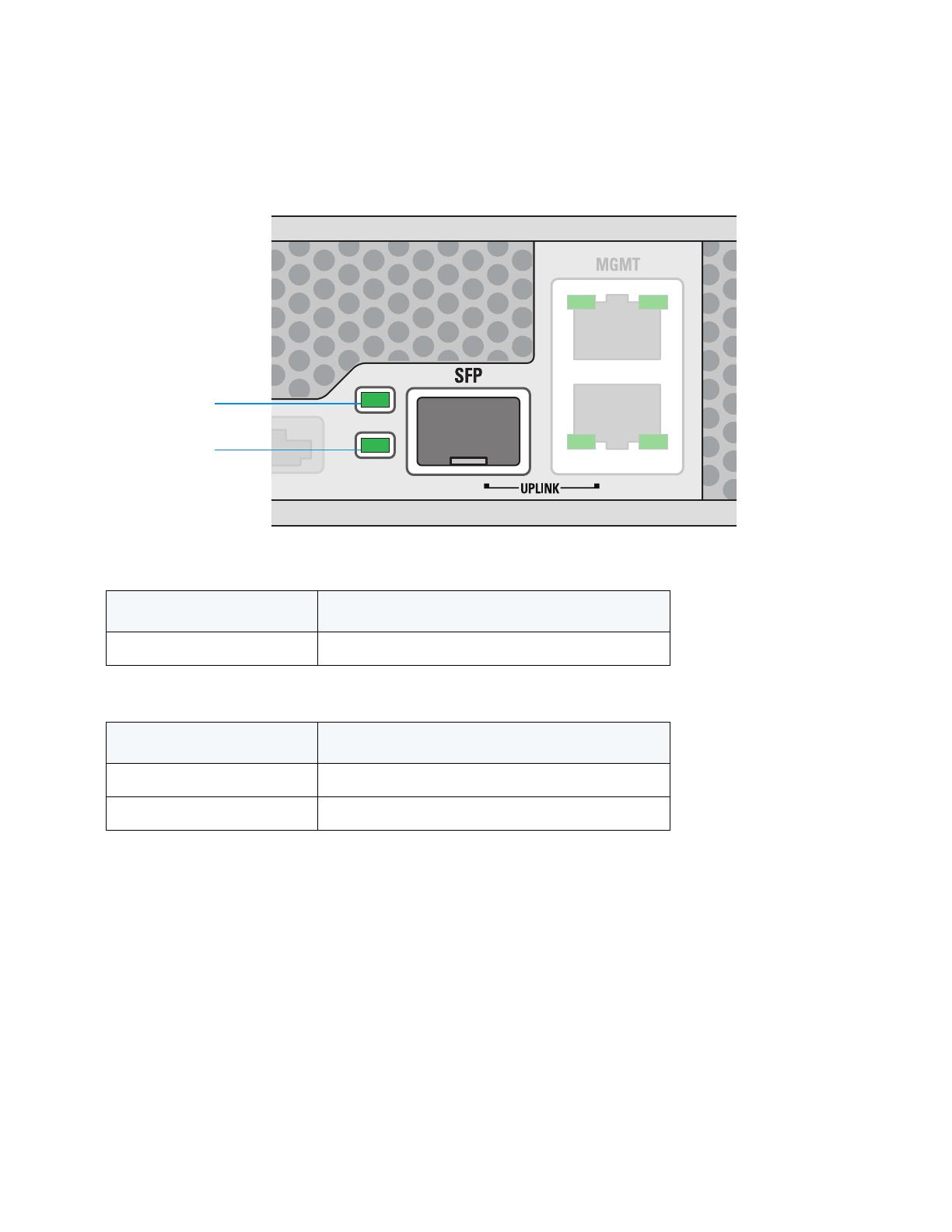
3.3 SFP Gigabit Ethernet LEDs
3.3.1 SFP Port Speed LED
3.3.2 SFP Port Status LED
Port Speed LED Event
Amber Solid 1000 Mbps
Port Status LED Event
Off No Link or Administratively shut down
Green Blinking Link present / Operational
Port speed
Port activity
LED Codes
10
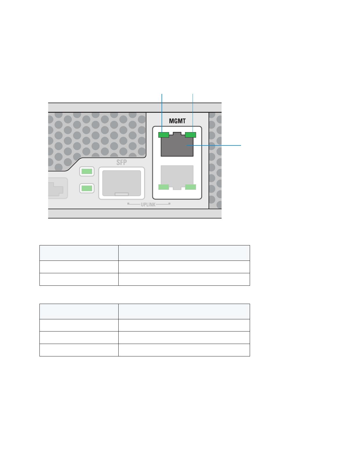
3.4 Management Port LEDs
3.4.1 Out of Band Management Port Speed LED
3.5 Out of Band Management Port Status LED
Port Speed LED Event
Off 10 Mbps
Green Solid 100 Mbps
Port Status LED Event
Off No Link
Green Solid Link present
Green Blinking Activity: Transmit and Receive
Management
port
Port
speed
Port
activity
Hardware Setup
11
4 Hardware Setup
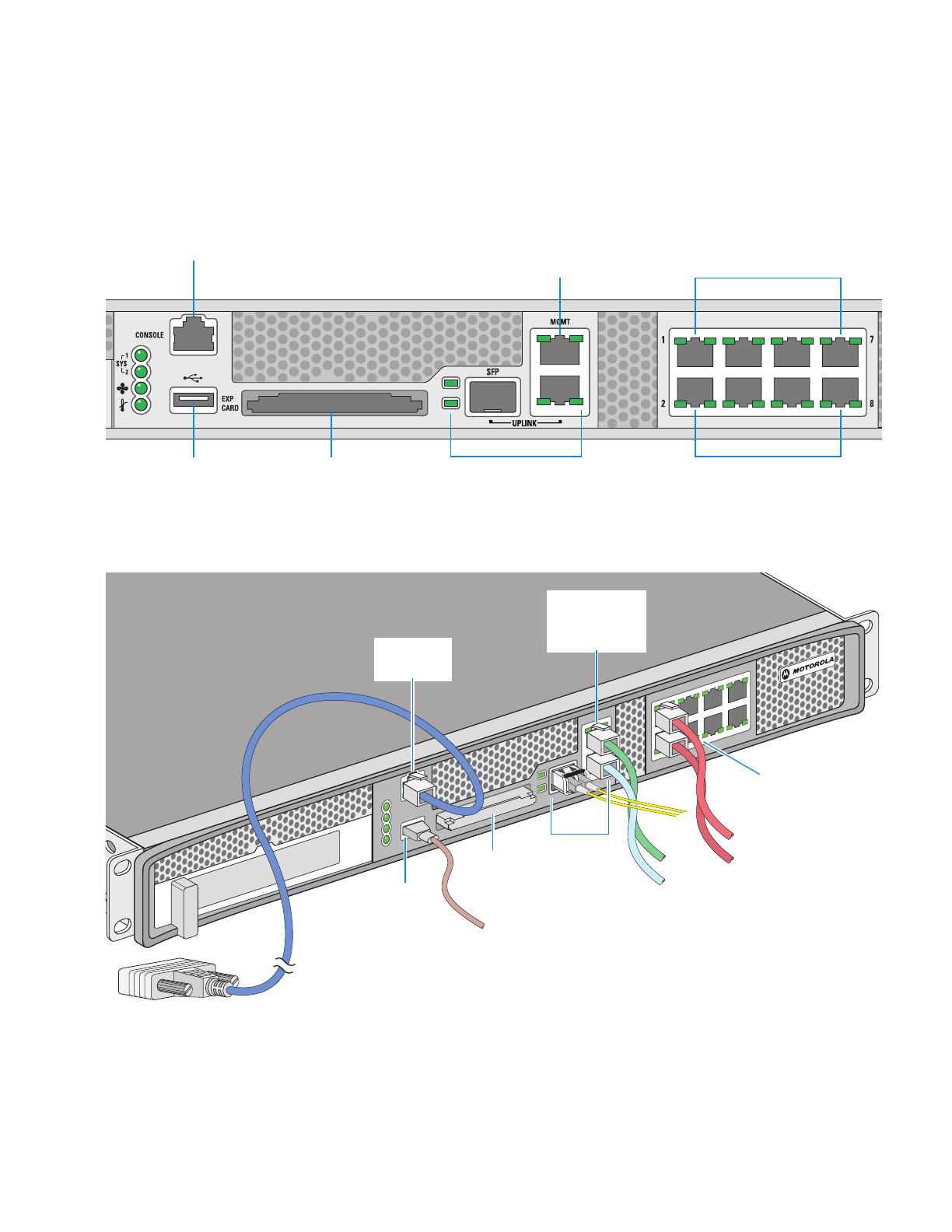
4.1 Cabling Information
The RFS6010 RF Switch has nine RJ-45 Gigabit Ethernet ports, one Gigabit SFP (fiber) port, one Out-
of-band management port and one Console connector. The above diagram shows each of those ports
and the cables or devices attached to them. The sections that follow describe detailed connection
and cabling information for each port. The switch also includes an ExpressCard slot for future
Out-of-band
management
Console
USB
ExpressCard
UPLINK
PoE enabled gigabit ethernet
ports 1, 3, 5, 7
Ports 2, 4, 6, 8
Gigabit Ethernet
RJ-45 connectors
with per-port LEDs
and PoE
USB
port
Out-of-band
management
port
ExpressCard
UPLINK
Console
connector
Hardware Setup
12
expansion. For software configuration, please see the Motorola RF Switch System Reference
available from the Motorola website.
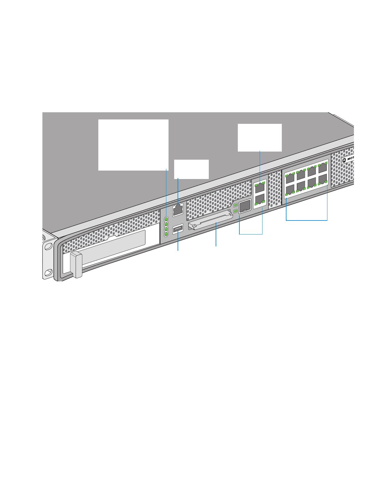
4.2 Gigabit Ethernet on the RFS6010 RF Switch
The RFS6010 RF Switch has nine RJ-45 Gigabit Ethernet ports and one Gigabit SFP (fiber optic) port.
Using the RJ-45 ports requires connecting a Category-6 Ethernet cable to the port. Each of the eight
ports support Power-over-Ethernet. To use the Gigabit SFP port, first install the SFP Module (Motorola
Part Number: Fiber-3000-1S-WWR).
System LEDs:
System Status 1
System Status 2
Fan Status
Temperature Status
Gigabit Ethernet
RJ-45 connectors
with per-port LEDs
USB
port
Console
connector
Out-of-band
management
port
ExpressCard
UPLINK

Hardware Setup
13
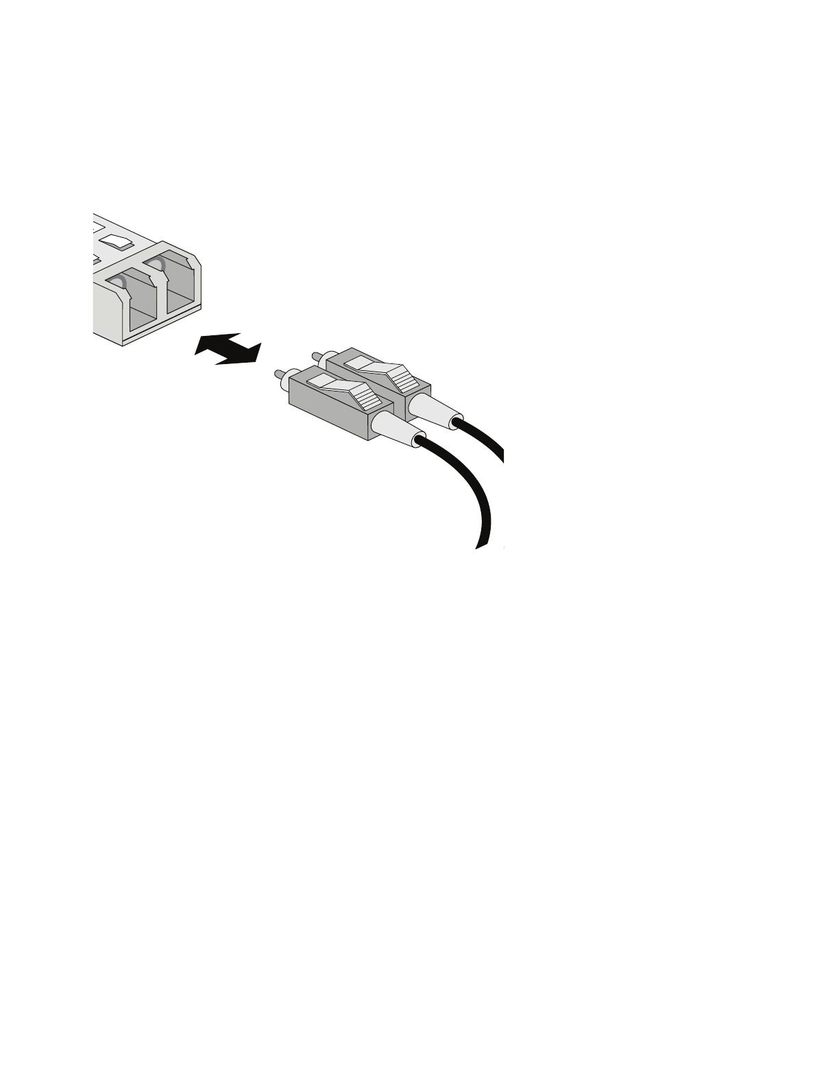
4.2.1 Installing the Gigabit Ethernet SFP
1. Open the bail on the transceiver.
2. Insert the SFP transceiver into the corresponding port on the switch.
3. Once the SFP transceiver is properly seated in the port, close the bail to lock the transceiver in
place.
Open bail to insert or remove
SFP transceiver
Close bail to lock
SFP transceiver in place
Hardware Setup
14
4. Insert the fiber optic cables into the installed transceiver.

Hardware Setup
15
4.3 Connecting USB Devices
The RFS6010 RF Switch contains one USB port for connecting USB flash storage devices to the
switch. The switch can use the USB flash storage device for file and log transfers. Follow the setup
instructions below to connect the devices to the switch and then access those devices through the
Web UI or Command Line Interface.
1. Connect the USB flash drive to the USB .
2. Wait a few seconds for the drive to be recognized by the switch.
3. Follow the instructions in the Motorola RF Switch System Reference or CLI Reference for more
information on accessing USB storage devices from the switch for file transfers or firmware
updates.
NOTE The switch supports USB flash devices formatted with FAT or VFAT
(FAT32) filesystems only. If your flash storage device is formatted with
another filesystem you will need to format
USB
port

Hardware Setup
16
4.4 Rack Mount Instructions
To install the RFS6000 Series RF Switch in a rack:
1. The rack mounting brackets are installed at the factory. No additional steps are needed.
2. Attach the brackets to the rack using screws appropriate for your rack’s mounting holes.
/