Page is loading ...

IMPORTANT INSTRUCTIONS TO THE INSTALLER:
PLEASE READ THESE INSTRUCTIONS, FILL IN THE BLANKS BELOW,
THEN PROVIDE THE INSTRUCTIONS TO THE USER BY SECURELY
TAPING THEM TO THE FLOW HANDLE OR THE ESCUTCHEON.
WARNING: Risk of scalding
Varying the calibration of this thermostatic valve to increase water
temperature increases the risk of injury from scalding. The installer is
responsible for installing the valve and any recalibration of the water
temperature in accordance with the instructions.
CAUTION: Danger of scald injury. Valve can be recalibrated to
provide higher temperature water.
This valve has been preset at the factory to provide a range of water
temperatures. Any change in settings or water inlet conditions from
those used during calibration at the factory may raise the outlet
temperature and may cause scalding. The responsibility for the
proper installation and any recalibration of this valve lies with the
installer.
TWO HANDLE THERMOSTATIC TUB/SHOWER FAUCET
T3428, T3428CP, T3428CPM, T3428STV, T3428NLBL, T3428CGPC,
T3428CGSA, T3429, T3429CP, T3429CPM, T3429STV, 3429NLBL,
T3429CGPC, T3429CGSA, T3431, T3431CP, T3431CPM, T3431STV,
T3431NLBL, T3431CGC, T3134CGSA
ENGLISH
INS235A
THIS THERMOSTATIC VALVE HAS BEEN PRESET
BY
OF
TO A MAXIMUM WATER DISCHARGE TEMPERATURE OF
______ºF. ANY CHANGE TO THIS SETTING MAY RAISE THE
DISCHARGE TEMPERATURE AND COULD CAUSE SCALDING.
DATE:__________
!
Complies with: ASME A112.18.1M, CSA B125, & ASSE 1016

1
For Safety and ease of faucet installation, Moen recommends
the use of these helpful tools.
Para la seguridad y facilidad de instalacion de la
mezcladora, Moen recomienda las siguientes herramientas.
Par mesure de sécurité et pour faciliter l’installation, Moen
suggère l’utilisation des outils suivants.
SAFETY GLASSES
GAFAS DE SEGURIDAD
LUNETTES DE SÉCURITÉ
TEFLON TAPE
CINTA DE TEFLON
RUBAN TÉFLON
PIPE WRENCH
LLAVE DE TUBO
CLÉ DE LAVABO
PHILLIPS SCREWDRIVER
DESTORNILLADOR DE ESTRELLA
TOURNEVIS À POINTE CRUCIFORME
FLASHLIGHT
LINTERNA
LAMPE DE POCHE
HEX WRENCH
LLAVE HEXAGONAL
CLÉ HEXAGONALE
PLUMBER'S PUTTY
MASILLA DE PLOMERO
MASTIC DE PLOMBIER
HELPFUL TOOLS HERRAMIENTAS UTILES OUTILS UTILES
Questions During
Installation?
1-800-BUY-MOEN
(1-800-289-6636)
Toronto 905-829-3400
Rest of Canada
1-800-465-6130
¿Preguntas durante la
instalación?
1-800-BUY-MOEN
(1-800-289-6636)
Toronto 905-829-3400
Resto del Canadá
1-800-465-6130
Des questions lors de
l’installation?
Toronto :
(905) 829-3400
Ailleurs au Canada :
1 800 465-6130

INSTALLATION INSTRUCTIONS
2
3
/4 - 3
3
/4"
Lookout Pipe
Finished Wall
8
3
2
2-3" 2-3"
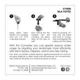
TUB SPOUT INSTALLATION
1/2” copper lookout (pipe protruding from wall)
must be 2 3/4" (70mm) min. to 3 3/4" (95mm)
max. in length and be free of deep scratches,
dents, kinks or bends. The cutoff end must be
free of burrs inside and out. Use of a tubing
cutter is recommended.
IF USING ADAPTER TO INSTALL SPOUT
WITH IPS CONNECTION:
Apply Teflon tape to thread and install into IPS
connection. Tighten with 9/16” socket wrench.
DO NOT use an open end wrench. Cut off 2 3/4-
3 3/4” from finished wall surface. Use of a tubing
cutter is recommended.
TO INSTALL SLIP FIT SPOUT:
Press and twist tub spout (8) onto the lookout
upside down and tightly up against the wall.
Tighten set screw with a 3/32" hex wrench until
it just starts to bind. Turn spout upright into
position against the wall and finish tightening
the set screw. DO NOT OVERTIGHTEN.
INSTALL SHOWER ARM
1/2” copper lookout (pipe protruding from wall)
must be 2” (50mm) min. to 3” (76mm) max. in
length and be free of deep scratches, dents,
kinks or bends. The cutoff end must be free of
burrs inside and out. Use of a tubing cutter is
recommended.
IF USING SHOWER ARM ADAPTER (3) - IPS
to CC: Apply Teflon tape to thread and install
into IPS connection. Tighten with 9/16” socket
wrench; DO NOT use an open end wrench. Cut
off 2-3” from finished wall surface. Use of a
tubing cutter is recommended.
TO INSTALL SLIP FIT SHOWER ARM: Press
and twist shower arm (2) onto the lookout
upside down and tightly up against the wall.
Tighten set screw with a 3/32” hex wrench
until it just starts to bind. Turn shower arm
upright into position against the wall and
finish tightening the setscrew. DO NOT
OVERTIGHTEN.
TO INSTALL SHOWERHEAD
Wrap shower arm thread with teflon tape.
Thread shower head onto shower arm. Tighten
shower head using a wrench on the flats
located on the shower ball. Hold shower arm
with one hand while tightening.
2
3
/4 - 3
3
/4 "2
3
/4 - 3
3
/4 "

ATTACH BASE ESCUTCHEON:
1. Turn off main hot and cold water supply to
valve.
2. Turn temperature extension near top of valve
body counter-clockwise until it stops (it may
already be in the full counter-clockwise
position).
3. Turn white flow extension near bottom of
valve body clockwise until it stops (it may
already be in the full clockwise position).
4. Place the base escutcheon (4) over the hole
in shower wall with larger hole in
the base escutcheon surrounding the top
threaded extension from the valve. The base
escutcheon will be correctly oriented when
the word “MOEN” is right side up.
5. Place the flat side of the two ring
escutcheons (5) against the base
escutcheon (4): one ring escutcheon over the
temperature extension and one ring
escutcheon over the white flow extension. At
this point, the ring escutcheons and base
escutcheon will be hanging from the
threaded extensions on the valve body.
LARGER HOLE AT TOP
TEMPERATURE EXTENSION
FLOW EXTENSION
5
4
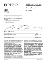
ATTACH TEMPERATURE KNOB:
1. Confirm that the temperature extension near
top of valve body is rotated fully counter-
clockwise.
2. Align the temperature knob to the
temperature extension with the number “9”
on the grip ring turned upward to the 12
o’clock position.
3. Move the temperature knob (6) towards the
temperature extension until the internal
splines (projections on the inner diameter) in
the temperature knob start to engage the
external splines on the temperature
extension.
4. After splines start to
engage, turn the lower shell
of the temperature knob
clockwise several turns while
holding the rubber grip to
prevent it from turning. This
turning will thread the internal
threads in the temperature
knob onto the threads on the
valve body. Continue turning
the lower shell (you may
release the rubber grip) until
the lower shell compresses
the ring escutcheon (5)
against the base escutcheon (4). It is helpful to
pull the lower shell towards you away from the
shower wall as you turn it to keep the knob from
disassembling. Note that as the temperature
knob nears the base escutcheon, the base
escutcheon and ring escutcheon will have to be
shifted upwards so that the ring escutcheon is
centered on the lower shell and the black plastic
part extending from the bottom of the
temperature knob fits within the hole in the base
escutcheon. Tighten the lower shell hand-tight
only. Verify that the “9” is still at the 12 o’clock
position. This completes the attachment of the
temperature knob.
Turn until "9" is at 12 o'clock position
Temperature extension turned
fully counter-clockwise
Use your hand to center the ring
escutcheon as the temperature
knob is threaded onto valve stem.
Lower shell
6
5
4
4
4

5
ATTACH FLOW HANDLE:
1. Confirm that the white flow extension is turned fully clockwise. Align the flow handle (7) to the
flow extension with the handle pointing downwards (6 o’clock position).
2. Move the flow handle towards the flow extension until the internal splines in the flow handle start
to engage the external splines on the flow extension.
3. After the splines start to engage, turn the shell of the flow handle (7) clockwise several turns
while holding the handle to prevent it from rotating. This turning will thread the internal threads
in the flow handle onto the threads on the valve body. Continue turning the shell (you may
release the handle) until it compresses the ring escutcheon (5) against the base escutcheon (4).
It is helpful to pull the shell towards you (away from the shower wall) as you turn it to keep the
knob from disassembling. Again, as the flow handle nears the base escutcheon, the ring
escutcheon will have to be shifted upwards so that the ring escutcheon is centered on the lower
shell. Tighten the shell hand-tight only. This completes the attachment of the flow handle. The
valve trim is now completely assembled and is ready for operation.
Flow extension turned
fully clockwise
Use your hand to center the ring
escutcheon as the handle is
threaded onto valve stem.
7
7
5
4
TESTING FOR PROPER OPERATION:
1. Make sure the flow handle (7) is still in the full down 6 o’clock position.
2. Turn on the hot and cold water supplies.
3. Turn the temperature knob fully counterclockwise so the number “9” is in the vertical 12 o’clock
position. The numbers represent increasing temperature. “9” is the hottest and “1” is the coldest.
4. Turn the flow handle counter-clockwise to start flow from the shower head or tub spout.
5. The thermostatic valve has a temperature range from 85°F (29°C) corresponding to the number
“1” on the temperature knob to 115°F (46°C) corresponding to the number “9” on the temperature
knob. If the temperature when the knob is set at “9” is not approximately 115°F (46°C), or if a
hotter maximum temperature is desired, the temperature range can be recalibrated by following
the instructions in the section “Recalibration Procedure.”
NOTE: Recalibration to a higher maximum temperature will increase the temperature
across the entire range.
CAUTION: RISK OF SCALDING HAZARD
The valve has been calibrated at the factory to provide a maximum water temperature
of 115°F (46°C). Any significant variation in the calibration or any variation in the water
supply temperatures (greater than 5°F or 3°C) from those used at the factory during
the calibration procedure can result in water temperatures that present scalding
dangers. Therefore, it is important to check the water temperature with the
temperature knob set at “9” to determine the maximum temperature of the water. The
responsibility for the proper installation and any recalibration of this valve lies with the
installer.
6. Turn the water off by turning the flow handle fully clockwise.
!

RE-CALIBRATION PROCEDURE
1. To re-calibrate the valve, it is necessary to
gain access to the spindle (located behind
the temperature extension near the top of
the valve).
2. Turn the temperature extension counter-
clockwise until it stops.
3. Loosen and remove the screw in the center
of the temperature extension by turning it
counterclockwise.
4. Carefully remove the temperature extension
without turning it or the spindle behind it.
You have now accessed the spindle.
5. To increase the temperature, rotate the
spindle counter-clockwise one or two
spline(s) past the mark on the retaining nut.
To decrease the temperature, rotate the
spindle clockwise one or two spline(s) past
the mark on the retaining nut.
6. Replace the temperature extension,
positioned fully counter-clockwise with the
tab as close as possible to the clockwise
side of the pin in the retaining nut. This
should be done without rotating the spindle.
Do not install the screw at this time.
7. Turn the flow handle counter-clockwise to
start the flow of water.
8. After the water temperature has stabilized,
check the temperature. This will be the new
maximum temperature. If the temperature is
not suitable, remove the temperature
extension as described above and repeat
this procedure to further adjust the water
temperature.
9. When the maximum temperature is
acceptable, re-install the screw in the
temperature extension and tighten.
10. Refer to “Attach Temperature Knob”
instructions on how to re-attach the
temperature knob.
Turn fully CCW
Temperature
extension tab
Temperature extension
Spindle
Retaining nut pin
Loosen and remove screw
6
Spindle w/ temperature
extension removed
Increase temperature
Decrease temperature
Retaining nut pin
Spindle with
temperature
extension in place

7
MOEN LIFETIME LIMITED WARRANTY
CONSUMER INFORMATION
Moen products have been manufactured under the highest standards of quality and workmanship. Moen
warrants to the original consumer purchaser for as long as the original consumer purchaser owns their home
(the “Warranty Period” for homeowners), that this faucet will be leak and drip-free during normal use and all
parts and finishes of this faucet will be free from defects in material and manufacturing workmanship. All other
purchasers (including purchasers for industrial, commercial and business use) are warranted for a period of 5
years from the original date of purchase (the “Warranty Period” for non-homeowners).
If this faucet should ever develop a leak or drip during the Warranty Period, Moen will FREE OF CHARGE
provide the parts necessary to put the faucet back in good working condition and will replace FREE OF CHARGE,
any part or finish that proves defective in material and manufacturing workmanship, under normal installation,
use and service. Replacement parts may be obtained by calling 1-800-289-6636 (Canada 1-800-465-6130),
or by writing to the address shown. Proof of purchase (original sales receipt) from the original consumer
purchaser must accompany all warranty claims. Defects or damage caused by the use of other than genuine
Moen parts are not covered by this warranty. This warranty is applicable only to faucets purchased after
December 1995 and shall be effective from the date of purchase as shown on purchaser’s receipt.
This warranty is extensive in that it covers replacement of all defective parts and finishes. However, damage
due to installation error, product abuse, product misuse, or use of cleaners containing abrasives, alcohol or
other organic solvents, whether performed by a contractor, service company, or yourself, are excluded from this
warranty. Moen will not be responsible for labor charges and/or damage incurred in installation, repair or
replacement, nor for any indirect, incidental or consequential damages, losses, injury or costs of any nature
relating to this faucet. Except as provided by law, this warranty is in lieu of and excludes all other warranties,
conditions and guarantees, whether expressed or implied, statutory or otherwise, including without restriction
those of merchantability or of fitness for use.
Some states, provinces and nations do not allow the exclusion or limitation of incidental or consequential
damages, so the above limitations or exclusions may not apply to you. This warranty gives you specific legal
rights and you may also have other rights which vary from state to state, province to province, nation to nation.
Moen will advise you of the procedure to follow in making warranty claims. Simply write to Moen Incorporated
using the address below. Explain the defect and include proof of purchase and your name, address, area code
and telephone number.
Faucets made of leaded brass alloys may contribute small amounts of lead to water that is allowed
to stand in contact with the brass. The amount of lead contributed by any faucet is highest when the
faucet is new. The following steps may reduce potential exposure to lead from faucets and other
parts of the plumbing system:
• Always run the water for a few seconds prior to use for drinking or cooking
• Use only cold water for drinking or cooking
• If you wish to flush the entire plumbing system of water that has been standing in the pipes or
other fittings, run the cold water until the temperature of the water drops, indicating water coming
from the outside main
• If you are concerned about lead in your water, have your water tested by a certified laboratory in
your area
HELPLINE:
1 (800) BUY-MOEN
[289-6636]
In the U.S. call our toll free Helpline number
for answers to any product, installation, or
warranty questions.
In Canada:
Toronto: 905-829-3400;
Rest of Canada: 1-800-465-6130
In Mexico:
(84) 88-08-26, 88-08-27,
o 91-800-84-345
/