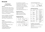
MC200CM V1

TP-LINK MC200CM V1, MC200CM, MC210CS, MC220L, MC220L Gigabit Ethernet Media Converter, tp-link MC220L Gigabit Ethernet Media Converter User manual

  • Hello! I am an AI chatbot trained to assist you with the TP-LINK MC200CM V1 User manual. I’ve already reviewed the document and can help you find the information you need or explain it in simple terms. Just ask your questions, and providing more details will help me assist you more effectively!
User Guide
MC200CM
MC210CS
MC220L
Gigabit Ethernet Media Converter
COPYRIGHT & TRADEMARKS
Specifications are subject to change without notice.
is a registered trademark of TP-LINK TECHNOLOGIES CO., LTD. Other
brands and product names are trademarks or registered trademarks of
their respective holders.
No part of the specifications may be reproduced in any form or by any
means or used to make any derivative such as translation,
transformation, or adaptation without permission from TP-LINK
TECHNOLOGIES CO., LTD. Copyright © 2011 TP-LINK
TECHNOLOGIES CO., LTD. All rights reserved.
http://www.tp-link.com
i
CONTENTS
Package Contents...........................................................................1
1. Introduction.............................................................................1
2. Features...................................................................................2
3. Appearance Indication ...........................................................3
3.1 LED Indicators................................................................. 3
3.2 Switch.............................................................................. 4
4. Installation Guides .................................................................5
4.1 Gigabit Ethernet Media Converter:.................................. 5
4.2 Configuration ................................................................... 7
4.3 Installation Procedure...................................................... 8
4.4 Install Media Converter into MC1400 .............................. 9
5. Troubleshooting ...................................................................10
6. Appendix: Specifications.....................................................11
1
Package Contents
Before starting using the products, make sure what you have is what you
ordered. The Converter includes:
¾ One Converter
¾ One AC-DC Power Adapter (DC9V/600mA)
¾ One User Guide
1. Introduction
MC200CM, MC210CS and MC220L are Gigabit Ethernet Media
Converters. The FX port of MC220L supports hot-swappable.
The converter mediates between a 1000Base-TX segment and a
1000Base-X segment. It is primarily designed for larger bandwidth, and
higher speed demanding workgroups that require expansion of the
Gigabit Ethernet network
Rear Panel Front Panel
MC200CM&MC210CS
2
Rear Panel Front Panel
MC220L
Note:
This media convertor can also be powered by 5VDC Adapter.
2. Features
¾ Comply with IEEE 802.3ab and IEEE 802.3z.
¾ Provide one SC/LC fiber connector and one RJ45 connector.
Please check the table in page 3 for the accurate connector of each
model.
¾ Work at 1000Mbps in Full-Duplex mode for both TX port and FX
port.
¾ Support auto MDI/MDIX for TX port.
¾ Extend fiber distance up to 0.55km for multi-mode fiber and 15km
for single-mode fiber. Please check the table in page 3 for the
accurate transmission distance of each model.
¾ Easy-to-view LED indicators provide status to monitor network
activity easily.
¾ External power supply.
3
¾ FX port supports hot-swappable(only for MC220L).
Connectors and Network Cables Supported
The connectors and network cables supported by the converter are
listed as follows.
¾ Connectors: RJ-45, SC, LC.
¾ Network Cables: Cat.5 Twisted-Pair(below abbreviated as TP),
9/125um Single-mode fiber, 62.5/125,50/125um Multi-mode fiber.
Model No.
Interface Transmission
Distance
Transmission
Media
Output
Center
Wavelength
MC200CM RJ45--SC
0.55km(50/125um)
0.22km(62.5/125um)
Multi-mode
Fiber,TP 850nm
MC210CS RJ45--SC 15km Single-mode
Fiber,TP 1310nm
MC220L RJ45--LC 0.55km/10km Multi/single-mode
850nm/1310
nm
SC fiber connector and LC fiber connector
3. Appearance Indication
3.1 LED Indicators
This converter has LED indicators which can provide a real-time report.
4
When you take a look at these indicators, you will know what’s
happening on your network.
Name Status Indication
On Power on
PWR Off Power off
On There’s a valid link for FX Port.
FX LINK
Off There’s no valid link for FX Port.
On There’s a valid link for TP Port.
LINK Off There’s no valid link for TP Port.
On The converter is receiving data from TP port.
TP
RX Off The converter is not receiving data from TP
port.
Note:
The TP port mentioned in this User Guide Manual stands for the TX port
without any explanations.
3.2 Switch
¾ FORCE: The FX port operates in FORCE mode.
PWR
RX
LINK
LINK
FX TP
Force AUTO
5
¾ AUTO: The FX port operates in Auto-Negotiation mode.
Note:
Be sure the opposite end is using the same setting. When using two
converters at the same time, the two converters must be set to FORCE
mode. When connected to other products, such as TL- SL2210WEB or
TL-SL2428WEB, the converter must be set to Auto- Negotiation mode.
We suggest leaving the switches on AUTO.
Please reset the converter after configuring the switches. Then the
change would take effect.
4. Installation Guides
4.1 Gigabit Ethernet Media Converter:
¾ The SC fiber connector of MC200CM transmits/receives data by
850nm short wave laser on multi-mode fiber.
¾ The SC fiber connector of MC210CS transmits/receives data by
1310nm short wave laser on single-mode fiber.
Transmits and receives data on different fibers
6
Note:
Either two MC200CM or two MC210CS could cooperate. MC220L can
be plugged in with two kinds of SFP modules, single-mode or
multi-mode.
Plug the SFP module into MC220L
Transmits and receives data between two MC220L
Note:
Two MC220L with the same SFP module could cooperate.
7
Transmits and receives data between MC220L and
MC200CM/MC210CS
Note:
MC220L could be connected to MC200CM or MC210CS, however, the
SFP module in MC220L must use the same mode and the same
wavelength as the opposite end. (Please refer to the table below) And
the connection fiber must be LC-SC fiber.
Model No. MC220L connect with MC200CM MC210CS
Transmission
Media SFP module 850nm, Multi-mode 1310nm,
Single-mode
4.2 Configuration
In order to achieve the aim of effectively expanding a Gigabit Ethernet
network, please take the following examples for reference:
1. Place two converters back to back between the following end
devices.
8
Note:
For the correct connection between 2 Media Converters, please refer to
connection diagram in 4.1 ---- two MC200CM, two MC210CS, two
MC220L or one MC220L with another MC200CM/MC210CS.
2. Another effective application is to place one converter directly
between a 1000Base-TX network and a fiber optic (FX) device.
4.3 Installation Procedure
Use a fiber cable to connect two converters, or connect a converter with
a 1000Base-FX Device.
1. Connection of a Converter and a 1000Base-TX Device (HUB or
Switch): Make sure that the length of the Cat.5 twisted pair cable
(Category-5) between the 1000Base-TX device and the converter is
less than 100 meters. Connect one end of the Cat.5 twisted pair
cable to the RJ45 jack on the converter and the other end of the
cable to the RJ45 jack on the 1000Base-TX device.
9
2. Connection of two Converters or a Converter and a 1000Base- FX
Device: Use a SC fiber cable to connect the two Converters’ SC
connectors or the SC connecters of a Converter and a
1000Base-FX Device.
3. Turn on the power.
4.4 Install Media Converter into MC1400
Tweak out the two screws located on either side of the Chassis’s one
side, and use them to install the retainer as follows.
1. Turn off the switch power, take off the front guard on the chassis,
insert the boxlike Media Converter you need in the slot of the
chassis, and use locking knob to lock it tightly as follows.
2. Turn on the switch power and you will see the Media Converter’s
10
POWER LED lit on. Then you can operate it as the boxlike Media
Converter of the MC series.
5. Troubleshooting
If you encounter some problems when you install or use this product,
please try to solve the problem according to the following steps. If it still
doesn’t work, please contact your dealer or ask for help from our
technical support.
1. PWR LED is off: The power error. Please check that whether the
power lead is connected correctly or not.
2. LINK LED (TP port) is off: Please confirm that there is no open
circuit with cable and make sure that the connection type of the
device is 1000M.
3. LINK LED (FX port) is off:
1) Check the fiber mode and fiber type to make sure that they
match the Gigabit transceivers.
2) Check out that whether there is an open circuit or not.
3) Check the fiber loss by the Fiber-Optic Tester to avoid the
excess wastage of the fiber.
4) Make sure that the FX port is connected correctly as following:
The transmitting port (TX) of local end is connected to the
receiving port (RX) of outlying end. And the receiving port (RX)
of local end is connected to the transmitting port (TX) of
outlying end.
11
6. Appendix: Specifications
MC200CM
Standards and Protocols IEEE802.3ab, IEEE 802.3z, IEEE 802.3x
Media Interface SC, RJ45
Cat.5: 100m
Max. Distance
Multi-mode Fiber: 0.55km
Power External Power Adapter
Operation: 0~40
Temperature
Storage: -40~70
Operation: 10%~90% non-condensing
Humidity
Storage: 5%~90% non-condensing
MC210CS
Standards and Protocols IEEE802.3ab, IEEE 802.3z, IEEE 802.3x
Media Interface SC, RJ45
Cat.5: 100m
Max. Distance
Single-mode Fiber: 15km
Power External Power Adapter
Operation: 0~40
Temperature
Storage: -40~70
Operation: 10%~90% non-condensing
Humidity
Storage: 5%~90% non-condensing
12
MC220L
Standards and Protocols IEEE802.3ab, IEEE 802.3z, IEEE 802.3x
Media Interface LC, RJ45
Cat.5: 100m
Max. Distance
Multi/Single-mode Fiber: 0.55km/10km
Power External Power Adapter
Operation: 0~40
Temperature
Storage: -40~70
Operation: 10%~90% non-condensing
Humidity
Storage: 5%~90% non-condensing
7106503685
/