Land Pride STH15 User manual
- Category
- Toys & accessories
- Type
- User manual
This manual is also suitable for

Table of Contents
Cover photo may show optional equipment not supplied
with standard unit.
For an Operator’s Manual and Decal Kit in French
Language, please see your Land Pride dealer.
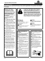
Read the Operator’s Manual entirely. When you see this symbol,
the subsequent instructions and warnings are serious - follow
without exception. Your life and the lives of others depend on it!
!
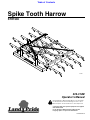
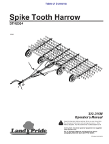
Spike Tooth Harrow
STH1590
322-314M
Operator’s Manual
Printed 5/9/19
33051

5/9/19STH1590 Spike Tooth Harrow 322-314M
Machine Identification
Record your machine details in the log below. If you replace this manual, be sure to transfer this information to the new
manual.
If you, or the dealer, have added Options not originally ordered with the machine, or removed Options that were
originally ordered, the weights and measurements are no longer accurate for your machine. Update the record by
adding the machine weight and measurements provided in the Specifications & Capacities Section of this manual with
the Option(s) weight and measurements.
Dealer Contact Information
Model Number
Serial Number
Machine Height
Machine Length
Machine Width
Machine Weight
Delivery Date
First Operation
Accessories
Name:
Street:
City/State:
Telephone:
Email:
WARNING: Cancer and reproductive harm - www.P65Warnings.ca.gov
!
California Proposition 65

Table of Contents
5/9/19
© Copyright 2019 All rights Reserved
Land Pride provides this publication “as is” without warranty of any kind, either expressed or implied. While every precaution has been taken in the
preparation of this manual, Land Pride assumes no responsibility for errors or omissions. Neither is any liability assumed for damages resulting from the use
of the information contained herein. Land Pride reserves the right to revise and improve its products as it sees fit. This publication describes the state of this
product at the time of its publication, and may not reflect the product in the future.
Land Pride is a registered trademark.
All other brands and product names are trademarks or registered trademarks of their respective holders.
Printed in the United States of America.
STH1590 Spike Tooth Harrow 322-314M
Table of Contents
Important Safety Information . . . . . . . . . . . . . 1
Safety at All Times . . . . . . . . . . . . . . . . . . . . . . . . . 1
Look For The Safety Alert Symbol . . . . . . . . . . . . . 1
Safety Labels . . . . . . . . . . . . . . . . . . . . . . . . . . . . . 6
Introduction . . . . . . . . . . . . . . . . . . . . . . . . . . . 7
Application . . . . . . . . . . . . . . . . . . . . . . . . . . . . . . . 7
Using This Manual . . . . . . . . . . . . . . . . . . . . . . . . . 7
Terminology: . . . . . . . . . . . . . . . . . . . . . . . . . . . . 7
Definitions: . . . . . . . . . . . . . . . . . . . . . . . . . . . . . . 7
Owner Assistance . . . . . . . . . . . . . . . . . . . . . . . . . . 7
Serial Number . . . . . . . . . . . . . . . . . . . . . . . . . . . 7
Further Assistance . . . . . . . . . . . . . . . . . . . . . . . . 7
Section 1: Assembly & Set-up . . . . . . . . . . . . 8
Tractor Requirements . . . . . . . . . . . . . . . . . . . . . . . 8
Torque Requirements . . . . . . . . . . . . . . . . . . . . . . . 8
Dealer Set-up . . . . . . . . . . . . . . . . . . . . . . . . . . . . . 8
Tractor Hook-Up . . . . . . . . . . . . . . . . . . . . . . . . . . . 9
Section 2: Adjustments . . . . . . . . . . . . . . . . . 10
Lower 3-Point Arm Leveling . . . . . . . . . . . . . . . . . 10
Center 3-Point Link Leveling . . . . . . . . . . . . . . . . . 10
Hitch Height & Chain Adjustment . . . . . . . . . . . . . 11
Spike Tooth Angle Adjustment . . . . . . . . . . . . . . . 11
Section 3: Operating Instructions . . . . . . . . 12
Operating Checklist . . . . . . . . . . . . . . . . . . . . . . . . 12
Safety Information . . . . . . . . . . . . . . . . . . . . . . . . . 12
Tractor Shutdown Procedure . . . . . . . . . . . . . . . . 12
Transporting . . . . . . . . . . . . . . . . . . . . . . . . . . . . . 12
Out-of-Field Inspection . . . . . . . . . . . . . . . . . . . . . 13
In-Field Inspection . . . . . . . . . . . . . . . . . . . . . . . . . 13
Field Uses . . . . . . . . . . . . . . . . . . . . . . . . . . . . . . . 13
Unhook Spike Tooth Harrow . . . . . . . . . . . . . . . . . 14
General Operating Instructions . . . . . . . . . . . . . . . 14
Section 4: Maintenance . . . . . . . . . . . . . . . . . 15
Maintenance . . . . . . . . . . . . . . . . . . . . . . . . . . . . . 15
Spike Tooth Replacement . . . . . . . . . . . . . . . . . . . 15
Long-Term Storage . . . . . . . . . . . . . . . . . . . . . . . . 16
Ordering Replacement Parts . . . . . . . . . . . . . . . . . 16
Section 5: Specifications & Capacities . . . . . 17
Section 6: Features & Benefits . . . . . . . . . . . 18
Section 7: Troubleshooting . . . . . . . . . . . . . . 19
Section 8: Torque values Chart . . . . . . . . . . . 20
Section 9: Warranty . . . . . . . . . . . . . . . . . . . . 21

Table of Contents Continued
5/9/19
Parts Manual QR Locator
The QR (Quick Reference) code on the
cover and to the left will take you to the
Parts Manual for this equipment.
Download the appropriate App on your
smart phone, open the App, point your
phone on the QR code and take a picture.
Dealer QR Locator
The QR code on the left will
link you to available dealers
for Land Pride products.
Refer to Parts Manual QR
Locator on this page for
detailed instructions.
STH1590 Spike Tooth Harrow 322-314M
Table of Contents
See previous page for Table of Contents.

Important Safety Information
5/9/19
1
Important Safety Information
These are common practices that may or may not be applicable to the products described in
this manual.
Tractor Shutdown & Storage
If engaged, disengage power
take-off.
Park on solid, level ground and
lower implement to ground or onto
support blocks.
Put tractor in park or set park
brake, turn off engine, and remove
switch key to prevent unauthorized
starting.
Relieve all hydraulic pressure to
auxiliary hydraulic lines.
Wait for all components to stop
before leaving operator’s seat.
Use steps, grab-handles and
skid-resistant surfaces when
getting on and off the tractor.
Detach and store implement in an
area where children normally do
not play. Secure implement using
blocks and supports.
OFF
R
E
M
O
VE
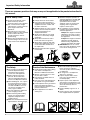
Look For The Safety Alert Symbol
The SAFETY ALERT SYMBOL indicates there is a
potential hazard to personal safety involved and extra
safety precaution must be taken. When you see this
symbol, be alert and carefully read the message that
follows it. In addition to design and configuration of
equipment, hazard control, and accident prevention are
dependent upon the awareness, concern, prudence, and
proper training of personnel involved in the operation,
transport, maintenance, and storage of equipment.
Safety Precautions for
Children
Tragedy can occur if the operator
is not alert to the presence of
children, Children generally are
attracted to implements and their
work.
Never assume children will remain
where you last saw them.
Keep children out of the work area
and under the watchful eye of a
responsible adult.
Be alert and shut the implement
and tractor down if children enter
the work area.
Never carry children on the tractor
or implement. There is not a safe
place for them to ride. They may
fall off and be run over or interfere
with the control of the power
machine.
Never allow children to operate the
power machine, even under adult
supervision.
Never allow children to play on the
power machine or implement.
Use extra caution when backing
up. Before the tractor starts to
move, look down and behind to
make sure the area is clear.
Safety at All Times
Careful operation is you best
insurance against an accident.
All operators, no matter how much
experience they may have, should
carefully read this manual and
other related manuals before
operating the power machine and
this implement.
It is the owner’s obligation to
instruct all operators in safe
operation.
Thoroughly read and understand
the “Safety Label” section, read all
instructions noted on them.
Do not operate the equipment
while under the influence of drugs
or alcohol as they impair the ability
to safely and properly operate the
equipment.
The operator should be familiar
with all functions of the tractor and
attached implement, and be able
to handle emergencies quickly.
Make sure all guards and shields
are in place and secured before
operating implement.
Keep all bystanders away from
equipment and work area.
Start tractor from the driver’s seat
with hydraulic controls in neutral.
Operate tractor and controls from
the driver’s seat only.
Never dismount from a moving
tractor or leave tractor unattended
with engine running.
Do not allow anyone to stand
between tractor and implement
while backing up to implement.
Keep hands, feet, and clothing
away from power-driven parts.
While transporting and operating
equipment, watch out for objects
overhead and along side such as
fences, trees, buildings, wires, etc.
Do not turn tractor so tight as to
cause hitched implement to ride
up on the tractor’s rear wheel.
Store implement in an area where
children normally do not play.
!
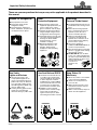
Be Aware of
Signal Words
A signal word designates a degree or
level of hazard seriousness. The
signal words are:
Indicates a hazardous situation that, if
not avoided, will result in death or
serious injury.
Indicates a hazardous situation that, if
not avoided, could result in death or
serious injury.
Indicates a hazardous situation that, if
not avoided, may result in minor or
moderate injury.
WARNING
CAUTION
!
!
DANGER
!

Important Safety Information
5/9/19
2
These are common practices that may or may not be applicable to the products described in
this manual.
Practice Safe Maintenance
Understand procedure before doing
work. Refer to the Operator’s
Manual for additional information.
Work on a level surface in a clean
dry area that is well-lit.
Use properly grounded electrical
outlets and tools.
Use correct tools and equipment for
the job that are in good condition.
Lower implement to the ground and
follow all shutdown procedures
before leaving the operator’s seat to
perform maintenance.
Allow equipment to cool before
working on it.
Disconnect battery ground cable (-)
before servicing or adjusting
electrical systems or before welding
on implement.
Do not grease or oil implement
while it is in operation.
Inspect all parts. Make certain
parts are in good condition &
installed properly.
Replace parts on this implement
with genuine Land Pride parts only.
Do not alter this implement in a way
which will adversely affect its
performance.
Remove buildup of grease, oil, or
debris.
Remove all tools and unused parts
from equipment before operation.
Use A Safety Chain
A safety chain will help control
drawn machinery should it
separate from the tractor drawbar.
Use a chain with the strength
rating equal to or greater than the
gross weight of the towed
implement.
Attach the chain to the tractor
drawbar support or other specified
anchor location. Allow only
enough slack in the chain to
permit turning.
Always hitch the implement to the
machine towing it. Do not use the
safety chain tow the implement.
Transport Safely
Comply with state and local laws.
Use towing vehicle and trailer of
adequate size and capacity. Secure
equipment towed on a trailer with
tie downs and chains.
Sudden braking can cause a towed
trailer to swerve and upset. Reduce
speed if towed trailer is not
equipped with brakes.
Avoid contact with any over head
utility lines or electrically charged
conductors.
Always drive with load on end of
loader arms low to the ground.
Always drive straight up and down
steep inclines with heavy end of a
tractor with loader attachment on
the “uphill” side.
Engage park brake when stopped
on an incline.
Maximum transport speed for an
attached equipment is 20 mph. DO
NOT EXCEED. Never travel at a
speed which does not allow
adequate control of steering and
stopping. Some rough terrains
require a slower speed.
As a guideline, use the following
maximum speed weight ratios for
attached equipment:
20 mph when weight of attached
equipment is less than or equal
to the weight of machine towing
the equipment.
10 mph when weight of attached
equipment exceeds weight of
machine towing equipment but
not more than double the weight.
IMPORTANT: Do not tow a load
that is more than double the weight
of the vehicle towing the load.
Tire Safety
Tire changing can be dangerous
and must be performed by
trained personnel using the
correct tools and equipment.
Always maintain correct tire
pressure. Do not inflate tires
above recommended pressures
shown in the Operator’s Manual.
When inflating tires, use a clip-on
chuck and extension hose long
enough to allow you to stand to
one side and NOT in front of or
over the tire assembly. Use a
safety cage if available.
Securely support the implement
when changing a wheel.
When removing and installing
wheels, use wheel handling
equipment adequate for the
weight involved.
Make sure wheel bolts have been
tightened to the specified torque.

Important Safety Information
5/9/19
3
These are common practices that may or may not be applicable to the products described in
this manual.
Avoid High
Pressure Fluids Hazard
Escaping fluid under pressure can
penetrate the skin causing serious
injury.
Before disconnecting hydraulic
lines or performing work on the
hydraulic system, be sure to
release all residual pressure.
Make sure all hydraulic fluid
connections are tight and all
hydraulic hoses and lines are in
good condition before applying
pressure to the system.
Use a piece of paper or
cardboard, NOT BODY PARTS, to
check for suspected leaks.
Wear protective gloves and safety
glasses or goggles when working
with hydraulic systems.
DO NOT DELAY. If an accident
occurs, see a doctor familiar with
this type of injury immediately. Any
fluid injected into the skin or eyes
must be treated within
a few hours or
gangrene may
result.
Wear
Protective Equipment
Wear protective clothing and
equipment appropriate for the job
such as safety shoes, safety
glasses, hard hat, and ear plugs.
Clothing should fit snug without
fringes and pull strings to avoid
entanglement with moving parts.
Prolonged exposure to loud noise
can cause hearing impairment or
hearing loss. Wear suitable
hearing protection such as
earmuffs or earplugs.
Operating equipment safely
requires the operator’s full
attention. Avoid wearing
headphones while operating
equipment.
Use Seat Belt and ROPS
Land Pride recommends the use
of a CAB or roll-over-protective-
structures (ROPS) and seat belt
in almost all power machines.
Combination of a CAB or ROPS
and seat belt will reduce the risk
of serious injury or death if the
power machine should be upset.
If ROPS is in the locked-up
position, fasten seat belt snugly
and securely to help protect
against serious injury or death
from falling and machine overturn.
Keep Riders Off
Machinery
Never carry riders or use tractor
to lift or transport individuals.
There is not a safe place for a
person to ride.
Riders obstruct operator’s view
and interfere with the control of
the power machine.
Riders can be struck by objects or
thrown from the equipment.
Prepare for Emergencies
Be prepared if a fire starts.
Keep a first aid kit and fire
extinguisher handy.
Keep emergency numbers for
doctor, ambulance, hospital, and
fire department near phone.
911
Use Safety
Lights and Devices
Slow moving tractors, and
self-propelled equipment can
create a hazard when driven on
public roads. They are difficult to
see, especially at night. Use the
Slow Moving Vehicle (SMV) sign
when on public roads.
Flashing warning lights and turn
signals are recommended
whenever driving on public roads.

Important Safety Information
5/9/19
4
Handle
Chemicals Properly
Protective clothing should be
worn.
Handle all chemicals with care.
Follow instructions on container
label.
Agricultural chemicals can be
dangerous. Improper use can
seriously injure persons, animals,
plants, soil, and property.
Inhaling smoke from any type of
chemical fire is a serious health
hazard.
Store or dispose of unused
chemicals as specified by the
chemical manufacturer.
These are common practices that may or may not be applicable to the products described in
this manual.
Avoid crystalline Silica
(quartz) Dust
Because crystalline silica is a basic
component of sand and granite,
many activities at construction sites
produce dust containing crystalline
silica. Trenching, sawing, and boring
of material containing crystalline
silica can produce dust containing
crystalline silica particles. This dust
can cause serious injury to the
lungs (silicosis).
There are guidelines which should
be followed if crystalline silica
(quartz) is present in the dust.
Be aware of and follow OSHA
(or other local, State, or Federal)
guidelines for exposure to airborne
crystalline silica.
Know the work operations where
exposure to crystalline silica may
occur.
Participate in air monitoring or
training programs offered by the
employer.
Be aware of and use optional
equipment controls such as water
sprays, local exhaust ventilation,
and enclosed cabs with positive
pressure air conditioning if the
machine has such equipment.
Otherwise respirators shall be worn.
Where respirators are required, wear
a respirator approved for protection
against crystalline silica containing
dust. Do not alter respirator in any
way. Workers who use tight-fitting
respirators can not have beards/
mustaches which interfere with the
respirator seal to the face.
If possible, change into disposable
or washable work clothes at the
work site; shower and change into
clean clothing before leaving the
work site.
Do not eat, drink, use tobacco
products, or apply cosmetics in
areas where there is dust containing
crystalline silica.
Store food, drink, and personal
belongings away from the work
area.
Wash hands and face before eating,
drinking, smoking, or applying
cosmetics after leaving the exposure
area.
Dig Safe - Avoid
Underground Utilities
USA: Call 811
CAN: digsafecanada.ca
Always contact your local utility
companies (electrical, telephone,
gas, water, sewer, and others)
before digging so that they may
mark the location of any
underground services in the area.
Be sure to ask how close you can
work to the marks they positioned.

Important Safety Information
5/9/19
5
This page left blank intentionally.

Important Safety Information
Table of Contents
STH1590 Spike Tooth Harrow 322-314M 5/9/19
6
Safety Labels
Your Spike Tooth Harrow comes equipped with all safety labels
in place. They were designed to help you safely operate your
implement. Read and follow their directions.
1. Keep all safety labels clean and legible.
2. Refer to this section for proper label placement. Replace
all damaged or missing labels. Order new labels from your
nearest Land Pride dealer. To find your nearest dealer,
visit our dealer locator at www.landpride.com.
3. Some new equipment installed during repair requires
safety labels to be affixed to the replaced component as
818-719C
Caution: Prevent Injury
33051
specified by Land Pride. When ordering new components
make sure the correct safety labels are included in the
request.
4. Refer to this section for proper label placement.
To install new labels:
a. Clean surface area where label is to be placed.
b. Spray soapy water onto the cleaned area.
c. Peel backing from label and press label firmly onto the
surface.
d. Squeeze out air bubbles with edge of a credit card or
with a similar type of straight edge.
Important Safety Information

Introduction
Table of Contents
STH1590 Spike Tooth Harrow 322-314M5/9/19
7
Introduction
Owner Assistance
The dealer should complete the Online Warranty
Registration at the time of purchase. This information is
necessary to provide you with quality customer service.
The parts on your Spike Tooth Harrow have been
specially designed by Land Pride and should only be
replaced with genuine Land Pride parts. Contact a Land
Pride dealer if customer service or repair parts are
required. Your Land Pride dealer has trained personnel,
repair parts, and equipment needed to service the
implement.
Serial Number
For quick reference and prompt service, record model
and serial number on the inside cover page and again on
the warranty page. Always provide model number and
serial number when ordering parts and in all
correspondences with your Land Pride dealer. For
location of your serial number plate, see Figure 1.
Figure 1
Further Assistance
Your dealer wants you to be satisfied with your new Spike
Tooth Harrow. If for any reason you do not understand
any part of this manual or are not satisfied with the
service received, the following actions are suggested:
1. Discuss any problems you have with your implement
with your dealership service personnel so they can
address the problem.
2. If you are still not satisfied, seek out the owner or
general manager of the dealership, explain the
problem, and request assistance.
3. For further assistance write to:
Land Pride Service Department
1525 East North Street
P.O. Box 5060
Salina, Ks. 67402-5060
E-mail address
33076
Land Pride welcomes you to the growing family of new
product owners. This Spike Tooth Harrow has been
designed with care and built by skilled workers using
quality materials. Proper assembly, maintenance, and
safe operating practices will help you get years of
satisfactory use from this harrow
Application
The STH1590 Spike Tooth Harrow is built and designed
by Land Pride for cutting through clods, manure, and
grasses to break up material into finer pieces so that it
can be spread evenly across the ground. The harrow
does and excellent job of smoothing garden plots, fields,
arenas, and landscaping areas. It loosens crusted soil,
aerates legume crops such as alfalfa and uncovers
overwintering insects. The harrow can be used to spread
manure, grass clippings, leaf litter, previous crop stubble,
and gravel driveways; and can incorporate into the soil
fertilizers, herbicides, granular products, broadcast seed,
and overseeding. It also helps to remove gopher mounds,
ant hills, ridges lift by tillage implements, sticks, and small
limbs from grassy areas.
Its 90" working width and Category I, 3-Point hitch makes
it compatible with tractors rated 20 hp minimum and is
Quick Hitch adaptable. The tooth can be adjusted to 10
different angles ranging from almost flat for providing the
best flow-through of residue to straight up & down for the
most aggressive position used to fluff up the soil.
See “Field Uses” on page 13, “Specifications &
Capacities” on page 17 and “Features & Benefits” on
page 18 for additional information.
Using This Manual
•
This Operator’s Manual is designed to help familiarize
the operator with safety, assembly, operation,
adjustments, troubleshooting, and maintenance. Read
this manual and follow the recommendations to help
ensure safe and efficient operation.
• The information contained within this manual was
current at the time of printing. Some parts may change
slightly to assure you of the best performance.
• To order a new Operator’s or Parts Manual, contact
your authorized dealer. Manuals can also be
downloaded, free-of-charge, from our website at
www.landpride.com
Terminology:
“Right” or “Left” as used in this manual is determined by
facing the direction the machine will operate while in use
unless otherwise stated.
Definitions:
IMPORTANT: A special point of information related
to the following topic. Land Pride’s intention is this
information must be read & noted before continuing.
NOTE: A special point of information that the
operator should be aware of before continuing.

Section 1: Assembly & Set-up
Table of Contents
STH1590 Spike Tooth Harrow 322-314M 5/9/19
8
Section 1: Assembly & Set-up
Set-up For Storage
Figure 1-1
33158
IMPORTANT: Always
pivot hitch frame down
when storing harrow
unhitched from tractor.
WARNING
!
To avoid serious injury or death:
• Wear a pair of gloves when adjusting angle of the spike
teeth to help protect hands from bruises and pinch points.
• The hitch can fall backwards unexpectedly when it is not
hooked to a tractor. Always store harrow with hitch pivoted
down onto the harrow frame when not hooked to a tractor.
• The spike teeth should be supported off the ground before
adjusting angle of spike teeth. Harrow may rotate suddenly
while removing bolt to change tooth angle creating a pinch
point hazard and/or falling hazard. Pulling on the angle
adjustment lever with teeth resting on the ground can strain
a person’s back and/or body extremities.
1. If necessary, readjust lever arm (#8) to protect hitch
frame (#5) from being scratched as it is rotated up.
Unwrap support chains (#4) from hitch frame (#5)
and carefully rotate hitch up to the position shown.
2. Loosen locknut (#7A) until bolt (#6A) pivots in hole of
gang bar (#2).
3. Remove bolt (#6B) from lever arm (#8) and reinsert
through center hole in adjustment bar (#3) and top
hole in lever arm (#8). Secure with locknut (#7B) and
tighten to the correct torque.
4. Attach end of support chains (#4) to right-hand and
left-hand side rails (#1) with 7/16"-14 x 1 1/4" GR5
cap screws (#6C), flat washers (#9), and hex
locknuts (#7C). Tighten nuts to the correct torque.
5. For safety, lay hitch frame down until resting on
adjusting bar (#3). See Figure 3-1 on page 14 for
illustration of how the harrow should be stored.
Tractor Requirements
Tractor horsepower and hitch category should be within
the range noted below. Tractors outside the horsepower
range must not be used.
Tractor Horsepower Rating . . . . . . . . . 20 hp minimum
3-Point Hitch Category . . . . . . . . . . . . . . . . . . . Cat. I
WARNING
!
To avoid serious injury or death:
Lightweight tractors with rear attached implements may need
weights added to the front to maintain steering control.
Consult your tractor Operator’s Manual to determine proper
weight requirements and maximum weight limitations.
Torque Requirements
Refer to “Torque Values Chart” on page 20 to
determine correct torque values for common bolts.
Dealer Set-up
Refer to Figure 1-1:
The STH1590 is shipped fully assembled with the hitch
frame pivoted down onto the harrow frame, bolt (#1), and
locknut (#2) stored in back hole “A” of adjustment
bar (#4) and the spike teeth are folded completely up.
Leave hitch and spike teeth in the folded up position
except when hitched to a tractor.

Section 1: Assembly & Set-up
Table of Contents
STH1590 Spike Tooth Harrow 322-314M5/9/19
9
Tractor Hook-Up
Figure 1-3
33053
NOTE: Clevis pin, hairpin, and linchpins are
furnished by customer.
Tractor Hook-Up
DANGER
!
To avoid serious injury or death:
A crushing hazard exists while hooking-up and unhooking
implement. Keep people and animals away while backing-up
to implement or pulling away from implement. Do not operate
hydraulic controls while a person or animal is directly behind
the power machine or near the implement.
A 3-Point Category I hitch is required. The lower 3-Point
arms of the 3-Point hitch must be stabilized to prevent
side-to-side movement. Most tractors have sway blocks
or adjustable chains for this purpose.
Refer to Figure 1-2:
1. Rotate hitch frame up to vertical position.
Refer to Figure 1-3:
2. Slowly back tractor up to the harrow while using the
3-Point hydraulic control lever to align lower 3-Point
arm holes with hitch pins.
3. Engage tractor park brake, shut tractor engine off,
and remove key before dismounting from tractor.
4. Attach lower arms to hitch pins and secure with
linchpins.
5. Connect top center 3-Point link to upper center hitch
point with clevis pin. Secure clevis pin with hairpin
cotter. (Clevis pin and hairpin are furnished by
customer.)
NOTE: Land Pride’s Cat. II Quick Hitch can be
attached to the tractor to provide quick and easy
3-point hook-up and detachment. See your nearest
Land Pride dealer to purchase a Quick-Hitch.
Rotate Hitch Frame up
Figure 1-2
6. Return to tractor and slowly raise harrow until off the
ground several inches.
7. Set 3-Point lift arms for lateral float.
8. See Lower 3-Point Arm Leveling on page 10 for
instructions on how to level the hitch frame from left
to right.
9. See Center 3-Point Link Leveling on page 10 for
instructions on leveling hitch frame front to back.
10. Make certain support chains are properly attached to
the main frame.
11. Return to the tractor and slowly raise and lower
harrow to ensure drawbar, tires, and other equipment
on the tractor do not make contact with harrow. Move
drawbar forward or remove it if it interferes.
33057

Section 2: Adjustments
Table of Contents
STH1590 Spike Tooth Harrow 322-314M 5/9/19
10
Lower 3-Point Arm Leveling
Refer to Figure 2-1:
1. Locate tractor with Spike Tooth Harrow on a flat, level
surface.
2. Use tractor’s hydraulic 3-Point control lever to lower
harrow until spike teeth are off the ground 2 to 3
inches.
WARNING
!
To avoid serious injury or death:
Always follow “Tractor Shutdown Procedure” provided in
this manual before dismounting the tractor.
3. Place a level on the harrow hitch as shown. Manually
adjust one or both lower 3-Point lift arms until hitch
frame is level from left to right. On some tractors, only
one arm can be adjusted vertically.
4. Continue with "Center 3-Point Link Leveling" on right
side of this page.
Deck Leveling
Figure 2-1
33077
Section 2: Adjustments
Center 3-Point Link Leveling
Refer to Figure 2-2:
Center 3-Point Link Adjustment
Figure 2-2
1. Lower harrow until teeth are resting on the ground.
2. Adjust length of center 3-Point link until upper center
hitch pin is vertically above lower 3-Point hitch pins.
This arrangement allows for optimum ground contour
following performance. A level placed against the
vertical edge of the hitch can be used to verify this
adjustment.
3. Lock center 3-Point link in this position.
NOTE: The bushing in the center of the hitch is
used when attaching the harrow with a Quick Hitch.
33078
Quick Hitch
Bushing
Adjust Center 3-Point
Link Until Upper Hitch
Pin is Vertically Above
Lower Hitch Pins.
LEVEL

Section 2: Adjustments
Table of Contents
STH1590 Spike Tooth Harrow 322-314M5/9/19
11
Hitch Height & Chain Adjustment
Refer to Figure 2-3:
1. Using tractor’s 3-Point hydraulic control lever, raise,
or lower 3-Point lift arms until harrow bars (#1)and
hitch pivot point (#2) are all an equal distance off the
ground from front to back when traveling forward.
2. Set tractor’s 3-Point hydraulic control lever stop at
this height.
1.
Remove linchpins (#3).
2.
Shorten or lengthen lift chains (#4) by dropping and
equal amount of links on both chains and inserting
the end link not dropped into slots (#5).
3.
Replace linchpins (#3). make sure they are secured
to the chain link.
Spike Tooth Angle Adjustment
WARNING
!
To avoid serious injury or death:
• Wear a pair of gloves when adjusting angle of the spike
teeth to help protect hands from bruises and pinch points.
IMPORTANT: The harrow bars (#1) and the hitch
pivot point (#2) should all be equal distance from the
ground as the harrow is pulled forward by the tractor.
It is subject to uneven tooth wear if one end is lower
than the other.
NOTE: Lift chains (#4) should sag to allow the
harrow to follow the contour of the ground when
going over raises such as terraces, but not so slack
that the back teeth will not raise soon after the front
is lifted off the ground.
• The spike teeth should be supported off the ground before
adjusting angle of spike teeth. Harrow may rotate suddenly
while removing bolt to change tooth angle creating a pinch
point hazard and/or falling hazard. Pulling on the angle
adjustment lever with teeth resting on the ground can strain
a person’s back and/or body extremities.
Refer to Figure 2-4:
1. Raise harrow up until spike teeth are off the ground.
2. Place supports tall enough to support the teeth off
the ground under the support harrow frame and then
lower harrow onto the supports.
3. Place gear selector in park, shut tractor engine off,
set park brake, and remove switch key.
4. Remove locknut (#4) and bolt (#3).
5. Move adjustment lever (#2) forward or backward to
the preferred spike tooth angle.
6. Align hole in adjustment bar (#1) with hole in
adjustment lever (#2) and secure with bolt (#3) and
locknut (#4). Tighten locknut to the correct torque.
Spike Tooth Angle Adjustment
Figure 2-4
33079
3-Point Height & Chain Adjustment
Figure 2-3
33055

Section 3: Operating Instructions
Table of Contents
STH1590 Spike Tooth Harrow 322-314M 5/9/19
12
Section 3: Operating Instructions
Operating Checklist
Hazard control and accident prevention are dependent
upon the awareness, concern, prudence and proper
training involved in the operation, transport, storage, and
maintenance of the Spike Tooth Harrow. Therefore, it is
absolutely essential that no one operates the unit unless
they are age 16 or older and have read, fully understood,
and are totally familiar with the Operator’s Manual. Make
sure the operator has paid particular attention to:
• Important Safety Information, page 1
• Section 1: Assembly & Set-up, page 8
• Section 2: Adjustments, page 10
• Section 3: Operating Instructions, page 12
• Section 4: Maintenance, page 15
Safety Information
WARNING
!
To avoid serious injury or death:
• Allow only persons to operate this implement who have
fully read and comprehended this manual, who have been
properly trained in the safe operation of this implement, and
who are age 16 or older. Serious injury or death can result
from the inability to read, understand, and follow
instructions provided in this manual.
• Always follow “Tractor Shutdown Procedure” provided in
this manual before dismounting the tractor.
• Never carry riders on the implement or tractor. Riders can
obstruct the operator’s view, interfere with control of the
equipment, be pinched by moving components, become
entangled in rotating components, be struck by objects, be
thrown or fall from the equipment, etc.
• Do not operate and/or travel across inclines where tractor
and/or implement can roll over. Consult your tractor’s
manual for acceptable inclines the tractor is capable of
traveling across.
• Do not allow children to play on or around stored
equipment. Children and/or stored equipment can fall
causing serious injury or death.
• Walk carefully around the harrow to prevent falling onto the
unit. Always store harrow with spike teeth pointing down.
• Beware of pinching fingers when changing the angle of the
spike teeth.
• Clear area to be worked of debris and other unforeseen
removable objects. Mark any potential hazards that cannot
be removed such as tree stumps, post, rocks, holes, drop-
offs, etc. with a visible flag.
• Do not use implement to lift objects; to pull objects such as
fence posts, stumps, etc; or to push objects. The unit is not
designed or guarded for these uses.
• Do not use implement to tow other equipment unless it is
designed with a tow hitch. Doing so can result in loss of
control and damage the equipment.
• Do not use implement as a man lift or work platform. It is
not properly designed or guarded for this use.
• Perform scheduled maintenance. Check for loose
hardware, missing parts, broken parts, structural cracks,
and excessive wear. Make repairs before putting implement
back into service.
• Avoid exposure to dust containing crystalline silica
particles. This dust can cause serious injury to the lungs
(silicosis). Because crystalline silica is a basic component
of sand and granite, many activities at construction sites
produce dust containing crystalline silica. Trenching,
sawing, and boring of material containing crystalline silica
can produce dust containing crystalline silica.
Tractor Shutdown Procedure
The following are basic tractor shutdown procedures.
Follow these procedures and any additional shutdown
procedures provided in your tractor Operator’s Manual
before leaving the operator’s seat.
1. Reduce engine speed and disengage power take-off
if engaged.
2. Park tractor and implement on level, solid ground.
3. Lower implement to ground or onto non-concrete
support blocks.
4. Put tractor in park or set park brake, turn off engine,
and remove switch key to prevent unauthorized
starting.
5. Relieve all hydraulic pressure to auxiliary hydraulic
lines.
6. Wait for all components to come to a complete stop
before leaving the operator’s seat.
7. Use steps, grab-handles and anti-slip surfaces when
stepping on and off the tractor.
Transporting
WARNING
!
To avoid serious injury or death:
When traveling on public roadways, travel in such a way that
faster moving vehicles may pass safely. Use accessory lights,
clean reflectors, and a slow moving vehicle sign that is visible
from the back to warn operators in other vehicles of your
presence. Always comply with all federal, state, and local
laws.
1. Reduce tractor ground speed when turning and leave
enough clearance so harrow does not contact
obstacles such as buildings, trees, or fences.
IMPORTANT: Do not add weights to the harrow.
Adding weights will cause high tooth wear and/or
bend harrow frame and bars.
IMPORTANT: Always raise harrow off the ground
before backing up. Backing up with spike teeth in the
ground can damage the harrow and tractor.

Section 3: Operating Instructions
Table of Contents
STH1590 Spike Tooth Harrow 322-314M5/9/19
13
2. Limit transport speed to 20 mph. Transport only with
a tractor of sufficient size and horsepower.
3. When traveling on roadways, transport in such a way
that faster moving vehicles may pass you safely.
4. Shift tractor to a lower gear when traveling over rough
or hilly terrain.
Out-of-Field Inspection
Make the following inspections with harrow attached to a
tractor:
1. Inspect tractor safety equipment to make sure it is in
good working condition.
2. Inspect harrow for loose bolts and nuts. Tighten all
loose bolts and nuts as indicated in the “Torque
Values Chart” on page 20.
3. Carefully raise and lower implement to ensure
drawbar, tires, and other equipment on the tractor do
not contact harrow frame.
4. Check for and remove foreign objects wrapped
around the spike teeth and frame. Block harrow up
before removing objects.
5. Check for missing, bent, broken, and worn spike
teeth. Replace spike teeth as required. Refer to
“Spike Tooth Replacement” on page 15.
6. Verify harrow is level from left to right and front to
back. See "Lower 3-Point Arm Leveling" and “Center
3-Point Link Leveling” on page 10.
In-Field Inspection
Do not harrow in wet conditions. Wet material will build up
causing the harrow to not be as effective.
1. Thoroughly inspect area to be harrowed for ditches,
drop-offs, stumps, post, rocks, and other unforeseen
objects that the harrow or tractor can snag on or hit.
Mark all potential hazards before working the area.
2. Verify harrow is set at the correct working height. See
“Hitch Height & Chain Adjustment” on page 11.
3. After the first 50 feet, stop and check to see that the
harrow is adjusted properly.
4. Periodically turn tractor off, remove switch key, and
check for foreign objects wrapped around the spike
teeth and frame. Block harrow up before removing
objects.
5. Frequently inspect the Spike Tooth Harrow for loose
bolts and nuts. Tighten all loose hardware as
indicated in the “Torque Values Chart” on page 20.
Field Uses
•
Firming Seedbeds
Most seedbeds are too loose and fluffy, Research
shows that by firming the seedbed, planting depth can
be better controlled resulting in huge increases (up to
54%) in germination rates. A firm seedbed also gives
better seed/soil contact for proper germination.
• Leveling Soil
Eliminates troublesome ridges left by some tillage
tools and helps provide consistent planting depth
across the width of the drill, seeder, or planter.
• Spreads Residue
This harrow handles large amounts of residue while
spreading it to manageable levels to allow tillage and
planting tools to do their job without the plugging
associated with heavy residue. It is a must-have tool
for processing no-till residue.
• Breaking-up Residue
This harrow pulled 7 to 10 MPH on a hot, dry day will
shatter residue, turning it into mulch.
• Conserving Moisture
Harrowing behind a primary tillage tool helps seal the
open soil and lowers the evaporation rate of moisture
in the freshly broken soil. Also, harrowing soil that has
crusted, breaks the capillary action that releases
moisture out of the soil.
• Controls Sprouting of Volunteer and Cheat
Dry years delay sprouting of volunteer. By stirring the
soil with the harrow, the dormant seed contacts the
moist soil and sprouts prior to planting season. This
allows time to control the volunteer and cheat before
planting a new crop.
• Incorporates herbicides
Preplant herbicides can be incorporated as deeply or
shallow as desired.
• Covers Broadcast Seed
Wheat pasture and cover crops can be planted
inexpensively by spreading the seed with a fertilizer
spreader and covering it with the harrow.
• Decreases Chemical Usage
Harrowing pulls out small weeds and volunteer,
uncovers overwinter insects to expose them to the
elements for fewer insects problems and firms the soil
to speed germination of weed and volunteer seed so
they can be destroyed prior to planting.
• Good for Alfalfa Fields
Makes a perfect alfalfa seedbed. Use on existing
alfalfa fields before spring to level the ground, control
gopher mounds and to pull out small weeds. It also
aerates the soil for root/oxygen exchange, breaks up,
and spreads clumps of old residue.
• Good for Grasslands
Grooms grass plants, knocks down gopher mounds
and pulls out small weeds.

Section 3: Operating Instructions
Table of Contents
STH1590 Spike Tooth Harrow 322-314M 5/9/19
14
Storage Position
Figure 3-1
Unhook Spike Tooth Harrow
WARNING
!
To avoid serious injury or death:
The hitch can fall backwards unexpectedly when it is not
hooked to a tractor. Always store harrow with hitch pivoted
down onto the harrow frame when not hooked to a tractor.
Un-hook Spike Tooth Harrow from the tractor as follows:
1. Park on a level solid surface.
2. Lower harrow to just off the ground or onto blocks that
support the harrow spike teeth above ground.
3. Engage tractor park brake, shut tractor engine off
and remove key before dismounting from tractor.
Refer to Figure 3-1:
4. Fold spike teeth to the angle shown with bolt (#4) in
the center hole of adjustment bar (#1) and top hole in
lever arm (#3).
5. Un-hook 3-Point hitch (#2) from tractor. Reinstall
hitch pins, linchpins, and hair pin cotters in harrow
hitch frame.
6. Lay hitch frame (#2) down onto adjustment bar (#1).
7. See "Long-Term Storage" information on page 16 if
harrow is being stored for a long time.
33052
General Operating Instructions
It is important that you familiarize yourself with the
Operator’s Manual, properly attached the harrow to your
tractor, made leveling adjustments, spike tooth angle
adjustments, pre-field inspections and field inspections
before using your Land Pride Spike Tooth Harrow.
Make sure before starting the tractor that it is out of gear,
the park brake is engaged, and the harrow is resting on
the ground. Start tractor and set engine throttle speed at
a low idle. Raise harrow with the tractor’s rear hydraulic
lift control lever to transport position making sure that the
tractor does not contact the harrow. Lower the harrow to
the ground and position the 3-Point adjustable stop on
the hydraulic lift lever so that the harrow can be
consistently returned to the same 3-Point hitch height for
field work.
You should now be ready to transport to your harrowing
site at a safe ground speed. On roadways transport in
such a manner that faster moving vehicles can easily see
you and pass you safely. Reduce your speed when
traveling over rough and hilly terrain. Avoid quick or sharp
steering corrections. Take extra care to ensure that the
harrow doesn’t come in contact with obstacles such as
trees, buildings, or fences. Use accessory lights and
appropriate reflective devices to provide adequate
warning to pedestrians and other vehicle operators when
traveling on public roads and in the dark of night. Comply
with all local, state, and federal laws.
It is important to inspect the area where you will be
harrowing and clear it of safety hazards and foreign
objects before harrowing the site. Never assume the area
is clear. Harrow only in areas you are familiar with and are
free of debris and unseen objects. In the event you do
strike an object, stop the harrow and tractor immediately
to inspect and make necessary repairs before resuming
operation. It really pays to inspect a new area and to
develop a safe plan before harrowing.
Now that you’re prepared and well briefed you may begin
harrowing. You will need to maintain 7 to 10 MPH ground
speed to shatter residue. Make a tractor gear and range
selection that will enable you to maintain these speed
combinations.
Avoid crossing the face of steep slopes and sharp drops.
Cross diagonally through dips to prevent hanging up the
tractor and harrow. Slow down in turns and make wide
turns when possible. Three-point hitch should be lifted
into transport position to make tight turns and to turn
around in the field. Try increasing or decreasing ground
speed to determine the effect on quality of work.
Remember to look back often.
With a little practice you will be pleased with what you and
your Land Pride Spike Tooth Harrow can do. Whether you
are done harrowing, need to take a break, or just need to
make a few adjustments to the harrow, remember to
reduce tractor’s engine rpm, stop on level ground, set
tractor park brake, turn off the engine, and remove the
key before dismounting from the tractor.

Section 4: Maintenance
Table of Contents
STH1590 Spike Tooth Harrow 322-314M5/9/19
15
Maintenance
Proper servicing and adjustments are key to the long life
of any implement. With careful inspection and routine
maintenance, you can avoid costly downtime and repair.
Check all bolts and pins after using the unit for several
hours and on a regular basis thereafter to ensure they are
tight and secured.
Replace worn, damaged, or illegible safety labels by
obtaining new labels from your Land Pride dealer.
DANGER
!
To avoid serious injury or death:
Always secure equipment with solid, non-concrete supports
before working under it. Never go under equipment supported
by concrete blocks or hydraulics. Concrete can break,
hydraulic lines can burst, and/or hydraulic controls can be
actuated even when power to hydraulics is off.
WARNING
!
To avoid serious injury or death:
• Allow only persons to perform maintenance on this
implement who have been properly trained in its safe
operation.
• Perform scheduled maintenance. Check for loose
hardware, missing parts, broken parts, structural cracks,
and excessive wear. Make repairs before putting implement
back into service.
• For safety reasons, each maintenance operation must be
performed with harrow lowered completely to the ground or
safely supported on blocks with tractor park brakes
engaged, engine shut off and ignition key removed.
• Do not alter implement or replace parts on the implement
with other brands. Other brands may not fit properly or
meet OEM (Original Equipment Manufacturer)
specifications. They can weaken the integrity and impair the
safety, function, performance, and life of the implement.
Replace parts only with genuine OEM parts.
Spike Tooth Replacement
Refer to Figure 4-1:
Always inspect spike teeth before each use. Make certain
they are properly installed and are in good working
condition. Replace any tooth that is lost, worn excessively,
or broken.
Replace spike teeth as follows:
1. Place tractor gear selector in park and set brakes,
shut engine off and remove ignition key.
2. Secure harrow in the up position with solid supports
before servicing underside of harrow.
3. Remove 1/2"-13 locknut (#2) and spike tooth (#3)
from harrow bar (#1).
4. Insert new spike tooth (#3) in harrow bar (#1) and
secure with 1/2"-13 new locknut (#2). Tighten locknut
to the correct torque.
Spike Tooth replacement
Figure 4-1
NOTE: Always replace spike teeth and locknuts at
the same time to ensure that the locknuts will not
come loose and allow the spike teeth to fall off.
33054
Section 4: Maintenance

Section 4: Maintenance
Table of Contents
STH1590 Spike Tooth Harrow 322-314M 5/9/19
16
Long-Term Storage
When you are ready to park or store your harrow, it is best
to park it on a dry hard packed gravel or concrete surface
where it remains visible and grass and weeds cannot
grow up through it. A harrow setting in deep grass and
weeds can be hard to locate and hazardous to vehicles,
livestock and people not seeing the harrow covered in
vegetation.
Clean, inspect, service, and make necessary repairs to
the implement when storing it for long periods and at the
end of the season. This will help to ensure the unit is
ready for field use the next time you hook-up to it.
DANGER
!
To avoid serious injury or death:
Always secure harrow in the up position with solid supports
before servicing underside of harrow. Never work under
equipment supported by hydraulics. Hydraulics can drop
equipment if controls are activated or if hydraulic lines burst.
Either situation can drop the harrow instantly even when
power to hydraulics is shut off.
CAUTION
!
To avoid minor or moderate injury:
The hitch when not hooked to a tractor can fall backwards
unexpectedly causing bodily injury. Always store harrow with
hitch pivoted down onto the harrow frame when not in use.
1. Clean off any dirt and grease that may have
accumulated on the harrow and moving parts.
Scrape off compacted dirt and then wash surface
thoroughly with a garden hose.
2. Check teeth and locknuts to make sure they are not
missing, broken, or excessively worn. Replace
harrow teeth as needed. See
“Spike Tooth
Replacement” on page 15
.
3. Inspect for loose, damaged, or worn parts and adjust
or replace as needed.
4. Repaint parts where paint is worn or scratched to
prevent rust. Ask your dealer for Land Pride aerosol
touch-up paint. Paint is also available in touch-up
bottles with brush, quarts, and gallon sizes by adding
TU, QT, or GL to the end of the aerosol part number.
Land Pride Touch-up Paint
Part No. Part Description
821-011C PAINT LP BEIGE SPRAY CAN
821-066C PAINT ORANGE SPRAY CAN
821-070C PAINT GP GLOSS BLACK SPRAY CAN
5. Replace all damaged or missing decals.
6. A coating of oil may also be applied to the teeth to
minimize oxidation.
7. Store harrow on a level surface in a clean, dry place.
Inside storage will reduce maintenance and make for
a longer harrow life.
8. Follow all unhooking instructions on page 14 when
disconnecting tractor from harrow.
Ordering Replacement Parts
Land Pride offers equipment in factory standard Beige
with black highlights. This implement is also available in
Orange.
When ordering an optional color, the suffix number
corresponding to the color must be added at the end of
the part number. Parts ordered without the suffix number
will be supplied in factory standard colors.
For example, if you are ordering a replacement part with
part number 555-555C and the existing part is orange,
then add the suffix 82 to the end of the number to make
the part number read 555-555C82.
82 . . . . . . . Orange 85. . . . . . . Black
Page is loading ...
Page is loading ...
Page is loading ...
Page is loading ...
Page is loading ...
Page is loading ...
-
 1
1
-
 2
2
-
 3
3
-
 4
4
-
 5
5
-
 6
6
-
 7
7
-
 8
8
-
 9
9
-
 10
10
-
 11
11
-
 12
12
-
 13
13
-
 14
14
-
 15
15
-
 16
16
-
 17
17
-
 18
18
-
 19
19
-
 20
20
-
 21
21
-
 22
22
-
 23
23
-
 24
24
-
 25
25
-
 26
26


Land Pride STH15 User manual
- Category
- Toys & accessories
- Type
- User manual
- This manual is also suitable for
Ask a question and I''ll find the answer in the document
Finding information in a document is now easier with AI
Related papers
-
 Land Pride STH2024 User manual
-
Land Pride AR25 Series User manual
-
 Land Pride DH35 Series User manual
-
Land Pride BB12 User manual
-
 Land Pride BB05 User manual
-
 Land Pride SBR Series User manual
-
 Land Pride DH10 User manual
-
 Land Pride DRG User manual
-
 Land Pride CA05 User manual
-
 Land Pride STB05 Series User manual


Other documents
-
Trio 9960-07 Owner's manual
-
Swisher 12593 Owner's manual
-
 Red Rock 8578775 Owner's manual
-
 Yard Tuff DH-045 Owner's manual
-
 Sansen FATA0970 User manual
-
TOPMAQ HM-1 User manual
-
Degelman STRAWMASTER PRO Series Quick start guide
-
Craftsman 36 in. Spike Aerator Manufacturer's Warranty
-
Worksaver FOH-5 User manual
-
Toro Wheel Tooth Kit, SGR-13 Stump Grinder Installation guide


