
Table of Contents
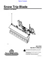
Cover photo may show optional equipment not supplied
with standard unit.
For an Operator’s Manual and Decal Kit in French
Language, please see your Land Pride dealer.
Read the Operator’s Manual entirely. When you see this symbol,
the subsequent instructions and warnings are serious - follow
without exception. Your life and the lives of others depend on it!
!
Snow Trip Blade
STB0554 & STB0560
301-701M
Operator’s Manual
Printed 4/7/21
74850

4/7/21STB0554 & STB0560 Snow Trip Blade 301-701M
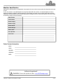
Machine Identification
Record your machine details in the log below. If you replace this manual, be sure to transfer this information to the new
manual.
If you, or the dealer, have added Options not originally ordered with the machine, or removed Options that were
originally ordered, the weights and measurements are no longer accurate for your machine. Update the record by
adding the machine weight and measurements provided in the Specifications & Capacities Section of this manual with
the Option(s) weight and measurements.
Dealer Contact Information
Model Number
Serial Number
Machine Height
Machine Length
Machine Width
Machine Weight
Delivery Date
First Operation
Accessories
Name:
Street:
City/State:
Telephone:
Email:
California Proposition 65
WARNING: Cancer and reproductive harm - www.P65Warnings.ca.gov
!

Table of Contents
4/7/21
© Copyright 2021 All rights Reserved
Land Pride provides this publication “as is” without warranty of any kind, either expressed or implied. While every precaution has been taken in the
preparation of this manual, Land Pride assumes no responsibility for errors or omissions. Neither is any liability assumed for damages resulting from the use
of the information contained herein. Land Pride reserves the right to revise and improve its products as it sees fit. This publication describes the state of this
product at the time of its publication, and may not reflect the product in the future.
Land Pride is a registered trademark.
All other brands and product names are trademarks or registered trademarks of their respective holders.
Printed in the United States of America.
-1
Table of Contents
Important Safety Information . . . . . . . . . . . . . 1
Safety at All Times . . . . . . . . . . . . . . . . . . . . . . . . . 1
Look for the Safety Alert Symbol . . . . . . . . . . . . . . . 1
Safety Labels . . . . . . . . . . . . . . . . . . . . . . . . . . . . . 6
Introduction . . . . . . . . . . . . . . . . . . . . . . . . . . . 9
Application . . . . . . . . . . . . . . . . . . . . . . . . . . . . . . . 9
Using This Manual . . . . . . . . . . . . . . . . . . . . . . . . . 9
Owner Assistance . . . . . . . . . . . . . . . . . . . . . . . . . . 9
Section 1: Assembly & Set-up . . . . . . . . . . . 10
Tractor Requirements . . . . . . . . . . . . . . . . . . . . . . 10
Before You Start . . . . . . . . . . . . . . . . . . . . . . . . . . 10
Torque Requirements . . . . . . . . . . . . . . . . . . . . . . 10
Tractor Shutdown Procedure . . . . . . . . . . . . . . . . 10
Cutting Edge Assembly . . . . . . . . . . . . . . . . . . . . . 10
Orange Marker Assembly . . . . . . . . . . . . . . . . . . . 11
Angling Options Assembly . . . . . . . . . . . . . . . . . . 12
Tractor Hook-Up . . . . . . . . . . . . . . . . . . . . . . . . . . 14
Hose Hook-Up . . . . . . . . . . . . . . . . . . . . . . . . . . . 14
Equipment Clearances . . . . . . . . . . . . . . . . . . . . . 14
Purging Hydraulic System . . . . . . . . . . . . . . . . . . . 14
Section 2: Adjustments . . . . . . . . . . . . . . . . 15
Skid Shoes . . . . . . . . . . . . . . . . . . . . . . . . . . . . . . 15
Locking and Unlocking Blade . . . . . . . . . . . . . . . . 15
Manual Angle Adjustment . . . . . . . . . . . . . . . . . . . 16
Spring Adjustment . . . . . . . . . . . . . . . . . . . . . . . . . 16
Section 3: Operating Procedures . . . . . . . . 17
Pre-Start Checklist . . . . . . . . . . . . . . . . . . . . . . . . 17
General Safety Information . . . . . . . . . . . . . . . . . . 17
Pre-Operation Inspection . . . . . . . . . . . . . . . . . . . 18
Snow Trip Blade Functions . . . . . . . . . . . . . . . . . . 18
Transporting . . . . . . . . . . . . . . . . . . . . . . . . . . . . . 18
Plowing Snow . . . . . . . . . . . . . . . . . . . . . . . . . . . . 19
Pushing Light Aggregate Materials . . . . . . . . . . . . 20
Unhooking the Blade . . . . . . . . . . . . . . . . . . . . . . . 20
General Operating Instructions . . . . . . . . . . . . . . . 20
Section 4: Optional Equipment . . . . . . . . . . 21
Steel and Poly Cutting Edge Options . . . . . . . . . . 21
Deflector Flap Option . . . . . . . . . . . . . . . . . . . . . . 21
Angling Options . . . . . . . . . . . . . . . . . . . . . . . . . . . 22
Tractor Hose & Coupler Options . . . . . . . . . . . . . . 22
Section 5: Maintenance & Lubrication . . . . 23
General Maintenance Information . . . . . . . . . . . . . 23
Cutting Edge Removal and Installation . . . . . . . . . 23
Hydraulics . . . . . . . . . . . . . . . . . . . . . . . . . . . . . . . 25
Long-Term Storage . . . . . . . . . . . . . . . . . . . . . . . . 25
Lubrication Points . . . . . . . . . . . . . . . . . . . . . . . . . 26
Section 6: Specifications & Capacities . . . . 27
Section 7: Features and Benefits . . . . . . . . . 28
Section 8: Troubleshooting . . . . . . . . . . . . . 29
Section 9: Torque Values Chart . . . . . . . . . . 30
Section 10: Warranty . . . . . . . . . . . . . . . . . . . 31

Table of Contents Continued
4/7/21
Parts Manual QR Locator
The QR (Quick Reference) code on the
cover and to the left will take you to the
Parts Manual for this equipment.
Download the appropriate App on your
smart phone, open the App, point your
phone on the QR code and take a picture.
Dealer QR Locator
The QR code on the left will
link you to available dealers
for Land Pride products.
Refer to Parts Manual QR
Locator on this page for
detailed instructions.
Table of Contents
0
See previous page for Table of Contents.

Important Safety Information
4/7/21
1
Important Safety Information
Listed below are common practices that may or may not be applicable to the products
described in this manual.
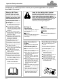
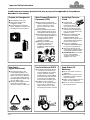
Safety at All Times
Careful operation is your best
assurance against an accident.
All operators, no matter how much
experience they may have, should
carefully read this manual and
other related manuals, or have the
manuals read to them, before
operating the power machine and
this attachment.
Thoroughly read and understand
the “Safety Label” section. Read
all instructions noted on them.
Do not operate the equipment
while under the influence of drugs
or alcohol as they impair the ability
to safely and properly operate the
equipment.
The operator should be familiar
with all functions of the tractor and
attachment and be able to handle
emergencies quickly.
Make sure all guards and shields
appropriate for the operation are in
place and secured before
operating the attachment.
Keep all bystanders away from
equipment and work area.
Start tractor from the driver’s seat
with hydraulic controls in neutral.
Operate tractor and controls from
the driver’s seat only.
Never dismount from a moving
tractor or leave tractor unattended
with engine running.
Do not allow anyone to stand
between tractor and attachment
while hooking-up.
Keep hands, feet, and clothing
away from power-driven parts.
While transporting and operating
equipment, watch out for objects
overhead and along side such as
fences, trees, buildings, wires, etc.
Store attachment in a safe and
secure area where children
normally do not play. When
needed, secure attachment
against falling with support blocks.
Look for the Safety Alert Symbol
The SAFETY ALERT SYMBOL indicates there is a
potential hazard to personal safety and extra precaution
must be taken. When you see this symbol, be alert and
carefully read the message that follows it. Hazard
control, and accident prevention are dependent upon the
awareness, concern, prudence, and proper training of
personnel involved in the operation, transport,
maintenance, and storage of equipment.
Tractor Shutdown & Storage
If engaged, disengage power
take-off.
Park on solid, level ground and
lower attachment to ground or
onto support blocks.
Put tractor in park or set park
brake.
Turn off engine and remove
ignition key to prevent
unauthorized starting.
Relieve all hydraulic pressure to
auxiliary hydraulic lines.
Wait for all components to stop
before leaving operator’s seat.
Use steps, grab-handles and
anti-slip surfaces when stepping
on and off the tractor.
OFF
R
E
M
O
V
E
Safety Precautions for
Children
Tragedy can occur if the operator
is not alert to the presence of
children. Children generally are
attracted to attachments and their
work.
Never assume children will remain
where you last saw them.
Keep children out of the work area
and under the watchful eye of a
responsible adult.
Be alert and shut the attachment
and tractor down if children enter
the work area.
Never carry children on the tractor
or attachment. There is not a safe
place for them to ride. They may
fall off and be run over or interfere
with the control of the power
machine.
Never allow children to operate the
power machine, even under adult
supervision.
Never allow children to play on the
power machine or attachment.
Use extra caution when backing
up. Before the tractor starts to
move, look down and behind to
make sure the area is clear.
!
Be Aware of
Signal Words
A signal word designates a degree or
level of hazard seriousness. The
signal words are:
Indicates a hazardous situation that, if
not avoided, will result in death or
serious injury.
Indicates a hazardous situation that, if
not avoided, could result in death or
serious injury.
Indicates a hazardous situation that, if
not avoided, may result in minor or
moderate injury.
WARNING
CAUTION
!
!
DANGER
!

Important Safety Information
4/7/21
2
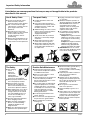
Listed below are common practices that may or may not be applicable to the products
described in this manual.
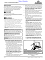
Transport Safely
Comply with federal, state, and
local laws.
Use towing vehicle and trailer of
adequate size and capacity. Secure
equipment towed on a trailer with
tie downs and chains.
Sudden braking can cause a towed
trailer to swerve and upset. Reduce
speed if towed trailer is not
equipped with brakes.
Avoid contact with any overhead
utility lines or electrically charged
conductors.
Always drive with load on end of
loader arms low to the ground.
Always drive straight up and down
steep inclines with heavy end of a
tractor with loader attachment on
the “uphill” side.
Engage park brake when stopped
on an incline.
Maximum transport speed for an
attached equipment is 20 mph. DO
NOT EXCEED. Never travel at a
speed which does not allow
adequate control of steering and
stopping. Some rough terrains
require a slower speed.
As a guideline, use the following
maximum speed weight ratios for
attached equipment:
20 mph when weight of attached
equipment is less than or equal
to the weight of machine towing
the equipment.
10 mph when weight of attached
equipment exceeds weight of
machine towing equipment but
not more than double the weight.
IMPORTANT: Do not tow a load
that is more than double the weight
of the vehicle towing the load.
Practice Safe Maintenance
Understand procedure before doing
work. Refer to the Operator’s Manual
for additional information.
Work on a level surface in a clean
dry area that is well-lit.
Lower attachment to the ground and
follow all shutdown procedures
before leaving the operator’s seat to
perform maintenance.
Do not work under any hydraulically
supported equipment. It can settle,
suddenly leak down, or be lowered
accidentally. If it is necessary to work
under the equipment, securely
support it with stands or suitable
blocking beforehand.
Use properly grounded electrical
outlets and tools.
Use correct tools and equipment for
the job that are in good condition.
Allow equipment to cool before
working on it.
Disconnect battery ground cable (-)
before servicing or adjusting
electrical systems or before welding
on equipment.
Inspect all parts. Make certain that
parts are in good condition &
installed properly.
Replace parts on this attachment
with genuine Land Pride parts only.
Do not alter this attachment in a way
which will adversely affect its
performance.
Do not grease or oil attachment
while it is in operation.
Remove buildup of grease, oil, or
debris.
Always make sure any material and
waste products from the repair and
maintenance of the attachment are
properly collected and disposed.
Remove all tools and unused parts
before operation.
Use A Safety Chain
A safety chain will help control
drawn machinery should it
separate from the tractor drawbar.
Use a chain with the strength
rating equal to or greater than the
gross weight of the towed
implement.
Attach the chain to the tractor
drawbar support or other specified
anchor location. Allow only
enough slack in the chain to
permit turning.
Always hitch the implement to the
machine towing it. Do not use the
safety chain to tow the implement.
Tire Safety
Tire changing
can be
dangerous
and must be
performed by
trained personnel using the
correct tools and equipment.
Always properly match the wheel
size to the properly sized tire.
Always maintain correct tire
pressure. Do not inflate tires
above recommended pressures
shown in the Operator’s Manual.
When inflating tires, use a clip-on
chuck and extension hose long
enough to allow you to stand to
one side and NOT in front of or
over the tire assembly. Use a
safety cage if available.
Securely support the implement
when changing a wheel.
When removing and installing
wheels, use wheel handling
equipment adequate for the
weight involved.
Make sure wheel bolts have been
tightened to the specified torque.

Important Safety Information
4/7/21
3
Listed below are common practices that may or may not be applicable to the products
described in this manual.
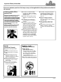
Prepare for Emergencies
Be prepared if a fire starts.
Keep a first aid kit and fire
extinguisher handy.
Keep emergency numbers for
doctor, ambulance, hospital, and
fire department near the phone.
911
Keep Riders Off
Machinery
Never carry riders on tractor or
implement.
Riders obstruct operator’s view
and interfere with the control of
the power machine.
Riders can be struck by objects or
thrown from the equipment.
Never use tractor or implement to
lift or transport riders.
Use Safety
Lights and Devices
Slow moving tractors, and
self-propelled equipment can
create a hazard when driven on
public roads. They are difficult to
see, especially at night. Use the
Slow Moving Vehicle (SMV) sign
when on public roads.
Flashing warning lights and turn
signals are recommended
whenever driving on public roads.
Use Seat Belt and ROPS
Land Pride recommends the use
of a CAB or roll-over-protective-
structures (ROPS) and seat belt
in almost all power machines.
Combination of a CAB or ROPS
and seat belt will reduce the risk
of serious injury or death if the
power machine should be upset.
If ROPS is in the locked-up
position, fasten seat belt snugly
and securely to help protect
against serious injury or death
from falling and machine overturn.
Wear Personal Protective
Equipment (PPE)
Wear protective clothing and
equipment appropriate for the job
such as safety shoes, safety,
glasses, hard hat, dust mask,
and ear plugs.
Clothing should fit snug without
fringes and pull strings to avoid
entanglement with moving parts.
Prolonged exposure to loud noise
can cause hearing impairment or
hearing loss. Wear suitable
hearing protection such as
earmuffs or earplugs.
Operating a machine safely
requires the operator’s full
attention. Avoid wearing
headphones while operating
equipment.
Avoid High Pressure
Fluids
Escaping fluid
under pressure will
penetrate the skin or
eyes causing serious injury.
Relieve all residual pressure
before disconnecting hydraulic
lines or performing work on the
hydraulic system.
Make sure all hydraulic fluid
connections are properly
tightened/torqued and all
hydraulic hoses and lines are in
good condition before applying
pressure to the system.
Use a piece of paper or
cardboard, NOT BODY PARTS,
to check for suspected leaks.
Wear protective gloves and
safety glasses or goggles when
working with hydraulic systems.
DO NOT DELAY. If an accident
occurs, seek immediate
emergency medical care or
gangrene may result.

Important Safety Information
4/7/21
4
Avoid crystalline Silica
(quartz) Dust
Because crystalline silica is a basic
component of sand and granite,
many activities at construction sites
produce dust containing crystalline
silica. Trenching, sawing, and boring
of material containing crystalline
silica can produce dust containing
crystalline silica particles. This dust
can cause serious injury to the
lungs (silicosis).
There are guidelines which should
be followed if crystalline silica
(quartz) is present in the dust.
Be aware of and follow OSHA
(or other local, State, or Federal)
guidelines for exposure to airborne
crystalline silica.
Know the work operations where
exposure to crystalline silica may
occur.
Participate in air monitoring or
training programs offered by the
employer.
Be aware of and use optional
equipment controls such as water
sprays, local exhaust ventilation,
and enclosed cabs with positive
pressure air conditioning if the
machine has such equipment.
Otherwise respirators shall be worn.
Where respirators are required, wear
a respirator approved for protection
against crystalline silica containing
dust. Do not alter respirator in any
way. Workers who use tight-fitting
respirators can not have beards/
mustaches which interfere with the
respirator seal to the face.
If possible, change into disposable
or washable work clothes at the
work site; shower and change into
clean clothing before leaving the
work site.
Do not eat, drink, use tobacco
products, or apply cosmetics in
areas where there is dust containing
crystalline silica.
Store food, drink, and personal
belongings away from the work
area.
Wash hands and face before eating,
drinking, smoking, or applying
cosmetics after leaving the exposure
area.
These are common practices that may or may not be applicable to the products described in
this manual.
Dig Safe - Avoid
Underground Utilities
USA: Call 811
CAN: digsafecanada.ca
Always contact your local utility
companies (electrical, telephone,
gas, water, sewer, and others)
before digging so that they may
mark the location of any
underground services in the area.
Be sure to ask how close you can
work to the marks they positioned.
Handle
Chemicals Properly
Protective clothing should be
worn.
Handle all chemicals with care.
Follow instructions on container
label.
Agricultural chemicals can be
dangerous. Improper use can
seriously injure persons, animals,
plants, soil, and property.
Inhaling smoke from any type of
chemical fire can be a serious
health hazard.
Store or dispose of unused
chemicals as specified by the
chemical manufacturer.

Important Safety Information
4/7/21
5
This page left blank intentionally.

Important Safety Information
Table of Contents
4/7/21STB0554 & STB0560 Snow Trip Blade 301-701M
6
Safety Labels
Your Snow Trip Blade comes equipped with all safety labels in
place. They were designed to help you safely operate your
attachment. Read and follow their directions.
1. Keep all safety labels clean and legible.
2. Refer to this section for proper label placement. Replace
all damaged or missing labels. Order new labels from your
nearest Land Pride dealer. To find your nearest dealer,
visit our dealer locator at www.landpride.com.
3. Some new equipment installed during repair requires
safety labels to be affixed to the replaced component as
specified by Land Pride. When ordering new components
make sure the correct safety labels are included in the
request.
4. Refer to this section for proper label placement.
To install new labels:
a. Clean the area the label is to be placed.
b. Spray soapy water on the surface where the label is to
be placed.
c. Peel backing from label. Press firmly onto the surface.
d. Squeeze out air bubbles with the edge of a credit card
or with a similar type straight edge.
74851
74851
Important Safety Information
838-112C
Danger: Pinching Hazard (2 places)
838-378C
Warning: Pinch Point & Crush Hazard


Introduction
Table of Contents
4/7/21
STB0554 & STB0560 Snow Trip Blade 301-701M
9
Owner Assistance
The dealer should complete the Online Warranty
Registration at the time of purchase. This information is
necessary to provide you with quality customer service.
The parts on your Snow Trip Blade have been specially
designed by Land Pride and should only be replaced with
genuine Land Pride parts. Contact a Land Pride dealer if
customer service or repair parts are required. Your Land
Pride dealer has trained personnel, repair parts, and
equipment needed to service the attachment.
Serial Number
For quick reference and prompt service, record model
and serial number on the inside cover page and again on
the warranty page. Always provide model number and
serial number when ordering parts and in all
correspondences with your Land Pride dealer. For
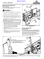
location of your serial number plate, see Figure 1.
Serial Number Plate Location
Figure 1
Further Assistance
Your dealer wants you to be satisfied with your new Snow
Trip Blade. If for any reason you do not understand any
part of this manual or are not satisfied with the service
received, the following actions are suggested:
1. Discuss the matter with your dealership service
manager making sure that person is aware of any
problems you may have and has had the opportunity
to assist you.
2. If you are still not satisfied, seek out the owner or
general manager of the dealership, explain the
question/problem, and request assistance.
3. For further assistance write to:
Land Pride Service Department
1525 East North Street
P.O. Box 5060
Salina, Ks. 67402-5060
E-mail address
lpservicedep[email protected]
74850
Introduction
Land Pride welcomes you to the growing family of new
product owners. This Snow Trip Blade has been
designed with care and built by skilled workers using
quality materials. Proper assembly, maintenance, and
safe operating practices will help you get years of
satisfactory use from this product.
Application
The STB0554 and STB0560 front-mounted Snow Trip
Blades are designed and built by Land Pride to meet the
needs of landscapers, farmers, ranchers, school
systems, and municipalities. The STB0554 and STB0560
blades are adapted for quick-attach front mounting on 17
to 30 hp (12.7 - 22.4 kW) sub compact tractor loaders.
These blades are primarily designed for snow removal
operations in the forward operating mode only. They are
also capable of pushing light aggregate materials such
as pea gravel or livestock feed such as shelled or ground
corn and silage. The trip blade design provides improved
protection against blade damage when unexpected
ground obstacles are encountered.
See “Specifications & Capacities” on page 27 and
“Features & Benefits” on page 28 for additional
information and performance enhancing options.
Using This Manual
•
This Operator’s Manual is designed to help familiarize
you with safety, assembly, operation, adjustments,
troubleshooting, and maintenance. Read this manual
and follow the recommendations to help ensure safe
and efficient operation.
• The information contained within this manual was
current at the time of printing. Some parts may change
slightly to assure you of the best performance.
• To order a new Operator’s or Parts Manual, contact
your authorized dealer. Manuals can also be
downloaded, free-of-charge, from our website at
www.landpride.com
Terminology
“Right” or “Left” as used in this manual is determined by
facing the direction the machine will operate while in use
unless otherwise stated.
Definitions
IMPORTANT: A special point of information related
to the following topic. Land Pride’s intention is that
this information must be read and noted before
continuing.
NOTE: A special point of information that the
operator should be aware of before continuing.

Section 1: Assembly & Set-up
Table of Contents
4/7/21STB0554 & STB0560 Snow Trip Blade 301-701M
10
Tractor Requirements
The Snow Trip Blade is designed to attach to tractor
loaders equipped with a universal quick-attach hitch with
the following requirements:
Horsepower Requirements . . 17-30 hp (12.7 - 22.4 kW)
Tractor Weight. . . . . . . . . Less than 2,000 lbs (900 kg)
Tractor Hitch . . . . . . . . . . . . . . . . . . . . . . . . ISO 24410
Max SAE Lift Capacity. . . Less than 1,000 lbs (450 kg)
Max Hydraulic Pressure Rating . . . . 3,000 psi (21 mPa)
Hydraulic Connections. . . . . . . . . . 2 - Hydraulic Outlets
Before You Start
Make sure the intended tractor conforms to the
requirements stated above. Also, read and understand
this Operator’s Manual for your Snow Trip Blade. An
understanding of how it works will aid in its assembly and
set-up.
Go through the Pre-Assembly Checklist before
assembling the Snow Trip Blade. To speed up your
assembly task and make the job safer, have all needed
parts and equipment readily at hand.
Pre-Assembly Checklist
Check Reference
Have a hoist, fork lift or loader with properly sized chains and
safety stands capable of lifting and supporting the equipment
on hand.
Have a minimum of two people available during assembly.
Make sure all major components and loose
parts are shipped with the machine.
Assembly
& Set-up
Double check to make sure all parts, fasteners,
and pins are installed in the correct location.
Refer to the Parts Manual if unsure. By double
checking, you will lessen the chance of
incorrectly using a bolt that may be needed
later.
NOTE: All assembled hardware from the
factory has been installed in the correct
location. Remember location of a part or
fastener if removed. Keep parts separated.
Operator’s
Manual
301-701M
Parts Manual
301-701P
Make sure working parts move freely, bolts are
tight & cotter pins are spread.
Operator’s
Manual
Make sure all grease fittings are in place and
lubricated.
Page 26
Make sure all safety labels are correctly
located and legible. Replace if damaged.
Page 6
Make sure all red and amber reflectors are
correctly located and visible when machine is
in transport position.
Page 8
NOTE: Hydraulic connections are only required if
the Snow Trip Blade is equipped with hydraulic
angling option.
IMPORTANT: Ballast may need to be added to your
tractor to maintain steering control and to prevent
tipping. Refer to your tractor’s operator manual to
determine if additional ballast is needed.
Torque Requirements
Refer to “Torque Values Chart for Common Bolt Sizes”
on page 30 to determine correct torque values when
tightening hardware.
Tractor Shutdown Procedure
The following are basic tractor shutdown procedures.
Follow these procedures and any additional shutdown
procedures provided in your tractor Operator’s Manual
before leaving the operator’s seat.
1. Reduce engine speed and shut-off all power to the
attachment.
2. Park tractor and attachment on solid, level ground.
3. Lower attachment until it is flat on the ground or on
non-concrete support blocks.
4. Put tractor in park or set park brake, turn off engine,
and remove ignition key to prevent unauthorized
starting.
5. Relieve all hydraulic pressure to auxiliary hydraulic
lines.
6. Wait for all components to come to a complete stop
before leaving the operator’s seat.
7. Use steps, grab-handles and anti-slip surfaces when
stepping on and off the tractor.
Cutting Edge Assembly
Land Pride offers two cutting edge options, steel cutting
edge and poly cutting edge, for the Snow Trip Blade. The
steel cutting edge for tougher applications and the poly
cutting edge for applications where you want to be more
gentle on the surface being bladed such as asphalt
parking lots.
Steel Cutting Edge Assembly
Refer to Figure 1-1 on page 11:
1. Locate steel cutting edge (#2) two plow bolts (#1)
and two hex flange locknuts (#4).
2. Insert plow bolt (#1) through the cutting edge (#2)
and moldboard (#3) on one end first and hand tighten
hex flange locknut (#4).
3. Repeat step 2 for the opposite end.
4. Install remaining bolts (#1) and hex flange
locknuts (#4).
5. Tighten nuts to proper torque.
6. Lower the Snow Trip Blade to level ground.
Poly Cutting Edge Assembly
Refer to Figure 1-2 on page 11:
1. Locate the poly cutting edge (#4) two carriage
bolts (#2), retaining plate (#1) and two hex flange
locknuts (#3).
2. Insert carriage bolt (#2) through the retaining
plate (#1), the cutting edge (#4) and moldboard (#5)
on one end first. Attach hex flange locknut (#3) and
hand tighten.
Section 1: Assembly & Set-up

Section 1: Assembly & Set-up
Table of Contents
4/7/21
STB0554 & STB0560 Snow Trip Blade 301-701M
11
3. Repeat step 2 for the opposite end.
4. Install remaining carriage bolts (#2) and hex flange
locknuts (#3).
5. Tighten nuts to proper torque.
6. Lower the Snow Trip Blade to level ground.
Steel Cutting Edge Assembly
Figure 1-1
Poly Cutting Edge Assembly
Figure 1-2
74858
2
1
4
3
74857
5
3
1
2
4
Orange Marker Assembly
Refer to Figure 1-3:
Land Pride offers 28" tall orange markers that can be
bolted to each side of the moldboard. They are ideal for
locating the outer ends of the blade when approaching
buildings, trees, poles, and other obstacles that could be
damaged and/or damage the Snow Trip Blade when hit.
1. Attach 28" orange marker (#4) to outer left edge of
moldboard (#1) with two 5/16"-18 x 1" GR5 hex head
cap screws (#3) and hex nylock nuts (#2).
2. Tighten nuts to the correct torque.
3. Repeat steps 1 and 2 for the right side.
Orange Marker Assembly
Figure 1-3
74859
4
1
2
3

Section 1: Assembly & Set-up
Table of Contents
4/7/21STB0554 & STB0560 Snow Trip Blade 301-701M
12
Angling Options Assembly
Land Pride offers two angling options for the Snow Trip
Blade. The Snow Trip Blade can be angled either
manually or hydraulically.
DANGER
!
To prevent serious injury or death:
Hydraulic fluid under pressure can penetrate skin. Wear
protective gloves and safety glasses or goggles when working
with hydraulic systems. Use a piece of cardboard or wood
rather than hands when searching for hydraulic leaks. If
hydraulic fluid is injected into the skin, it must be treated by a
doctor within a few hours or gangrene may result.
IMPORTANT: Make sure threads and inside of
fittings and hoses are clean.
Manual Angle-Bent Pin Assembly
Refer to Figure 1-4:
1. Drive 1/4" x 1 3/4" roll pin (#1) through bent pin (#2).
2. Align holes on the pivot weldment and hitch
assembly to desired angle.
3. Push the bent pin assembly through holes as shown.
Manual Angle-Bent Pin Assembly
Figure 1-4
2
1
74860

Section 1: Assembly & Set-up
Table of Contents
4/7/21
STB0554 & STB0560 Snow Trip Blade 301-701M
13
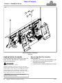
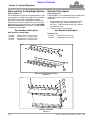
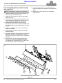
Hydraulic Angle-Single Cylinder Assembly
Refer to Figure 1-5:
1. Attach base end of cylinder (#3) to hitch assembly
lug (#5) with clevis pin (#2) and cotter pins (#1).
2. Attach rod end of hydraulic cylinder (#3) to pivot
weldment lug (#7) with clevis pin (#9) and
cotter pin (#8).
3. Remove cylinder port plugs.
4. Locate adapter (#10) with a small orifice opening in
one end. Attach that adapter to the rod end of
hydraulic cylinder (#3). Attach the other adapter (#4)
to the base end. Tighten adapters.
5. Attach hoses (#6) to adapters (#10) and (#4) and
tighten.
6. Thread two 5/16"-18 hex nuts (#12) to U-bolt (#11).
7. Place U-bolt (#11) through the holes in hitch
weldment (#14) and fasten with two 5/16"-18 hex
nuts (#13).
8. Wrap hoses (#6) together with hose wrap (#15).
9. Thread hoses (#6) through U-bolt (#11).
NOTE: U-bolt (#11) can be angled to the left or right
or it can be centered.
NOTE: Wrap hose wrap (#15) to hoses (#6) so that
the hose wrap (#15), not the hoses (#6), comes in
contact with U-bolt (#11).
Hydraulic Angle-Single Cylinder Assembly
Figure 1-5
3
5
2
1
8
9
10
4
7
6
13
11
12
14
74861
15
Orifice Fitting

Section 1: Assembly & Set-up
Table of Contents
4/7/21STB0554 & STB0560 Snow Trip Blade 301-701M
14
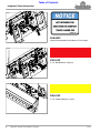
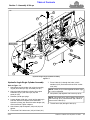
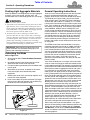
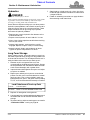
Tractor Hook-Up
Refer to Figure 1-8:
DANGER
!
A crushing hazard exists while hooking-up and unhooking the
attachment. Do not allow anyone to stand between attachment
and power machine while approaching or backing away from
the attachment. Do not operate lift and/or tilt controls while
someone is near the power machine and/or attachment.
1. Make sure hydraulic hoses do not interfere with hitch
hook-up.
2. Drive tractor to the blade making sure the tractor front
hitch plate is parallel with the blade hitch plate.
3. Tilt top of the loader hitch plate slightly forward and
position top of hitch plate under the top angled bar on
the Snow Trip Blade hitch plate.
4. Slowly lift loader hitch until the top angle bar and
loader hitch have come together.
5. Push lock handles on the loader hitch down into
locked position. Check to make sure that the lock
pins go through the bottom slots of the Snow Trip
Blade hitch plate.
Snow Trip Blade Hitch Plate
Figure 1-8
Hose Hook-Up
DANGER
!
To prevent serious injury or death:
Hydraulic fluid under pressure can penetrate skin. Wear
protective gloves and safety glasses or goggles when working
with hydraulic systems. Use a piece of cardboard or wood
rather than hands when searching for hydraulic leaks. If
hydraulic fluid is injected into the skin, it must be treated by a
doctor within a few hours or gangrene may result.
1. Route hydraulic hoses through the most convenient
path to access your power equipment couplings.
2. Clean quick connect couplers of dirt and then
connect couplers to the tractor remote outlets. Make
sure quick connect couplers have fully engaged.
74862
Top Angle Bar
Bottom slots
IMPORTANT: Make sure coupler fittings on
hydraulic hoses and tractor are clean before
connecting them together.
If they have not, check the following:
a. Make sure couplers are same size and type.
b. Make sure hydraulic pressure has been released.
3. Extend and retract hydraulic cylinder with tractor
controls. Switch hoses on tractor remote outlets if the
blade angles to the opposite direction intended.
4. For additional help, refer to hydraulic hook-up in your
tractor Operator’s Manual.
Equipment Clearances
It is important to check clearance before putting unit into
operation. If equipped with hydraulic angle, make sure
hoses are long enough and won’t become pinched or
entangled in the equipment. Also, make sure the Snow
Trip Blade moldboard does not come in contact with
tractor frame and tires by carefully going through its full
range of motions.
1. Visually inspect hydraulic hoses for possible pinch
points and shortness. Make hose adjustments before
starting the machine.
2. Start tractor and raise blade off the ground
approximately 12" (30 cm). If necessary, have
someone stand nearby that can motion to the
operator to stop if a problem develops.
3. Fully extend angle cylinder to angle blade right and
then fully extend and tilt cylinders on end of loader
arms while watching for interferences with hydraulic
hoses and blade.
4. Fully retract angle cylinder then fully extend and
retract tilt cylinders while watching for interferences
with hydraulic hoses and blade.
5. Raise blade fully up and repeat steps 3 & 4 above.
Purging Hydraulic System
1. With blade raised off the ground about 12" (30 cm),
cycle angle cylinder several times from fully extended
to fully retracted.
2. If cylinder operates unevenly after cycling it several
times, then purge the system as follows:
a. Fully retract angle cylinder.
b. Loosen fitting on base end.
c. Use hydraulic system to extend angle cylinder
until air is purged.
d. Tighten fitting.
e. Fully extend angle cylinder.
f. Loosen fitting on rod end.
g. Use hydraulic system to retract angle cylinder until
air is purged.
h. Tighten fitting.
IMPORTANT: The hydraulic cylinder and/or hoses
can contain air and should be purged before use.
Not purging the cylinder and hoses of air can cause
uneven jerky cylinder movement.

Section 2: Adjustments
Table of Contents
4/7/21
STB0554 & STB0560 Snow Trip Blade 301-701M
15
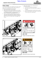
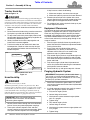
Skid Shoes
Refer to Figure 2-1:
The skid shoes mounted on the back of the moldboard
should be adjusted vertically according to the surface
they are running over. Doing so will reduce the chance of
blade or surface damage during snow removal on gravel
or loose stone driveways.
1. Operate your loader lift lever to raise the Snow Trip
Blade off the ground high enough to remove skid
shoes (#1).
2. Place support blocks under the cutting edge and
lower the Snow Trip Blade until it rests on the blocks.
3. Shut tractor down. See “Tractor Shutdown
Procedure” on page 10.
4. Remove linchpin (#4) and linchpin protector (#5)
from skid shoe (#1).
5. Adjust height up or down to your preference by
adding or removing spacers (#3) from under the skid
shoe mount (#2).
6. Re-install linchpin protector (#5) and re-attach
linchpin (#4) to the skid shoe (#1).
Skid Shoe Adjustment
Figure 2-1
NOTE: For working snow, the skid shoes should be
3/8" to 3/4" below the bottom of the cutting edge. For
working dirt, the skid shoes should be above the
bottom of the cutting edge or removed.
74864
3
2
1
5
4
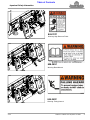
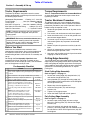
Locking and Unlocking Blade
Refer to Figure 2-2:
The Snow Trip Blade may also be used for pushing loose
dirt and other light materials. The blade must be in the
locked position to do so.
1. Rest the Snow Trip Blade on level ground.
2. Shut tractor down.See “Tractor Shutdown
Procedure” on page 10.
3. To lock the Snow Trip Blade for working loose dirt and
other light material, remove 1/2-13X1 1/2 GR5 round
head square neck bolts (#1) from holes (A). Insert
bolts (#1) in holes (B) as shown and fasten with hex
flanged whiz nuts (#2).
4. Tighten to correct torque.
Locking/Unlocking Blade
Figure 2-2
NOTE: When working snow, the blade must be
unlocked. Bolts (#1) and nuts (#2) should be
assembled in holes (A) to prevent misplacing them.
NOTE: Do not operate the Snow Trip Blade in the
unlocked position when working loose dirt or similar
materials.
IMPORTANT: Attempting to work undisturbed soil,
heavy materials or similar items can damage the
Snow Trip Blade and will void all warranties.
74866
2
2
1
B
A
B
A
Unlocked
Locked
Section 2: Adjustments

Section 2: Adjustments
Table of Contents
4/7/21STB0554 & STB0560 Snow Trip Blade 301-701M
16
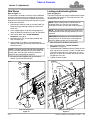
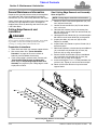
Manual Angle Adjustment
Refer to Figure 2-4:
Holes are provided for angling the blade on each side of
center in 12
o
increments up to 24
o
.
WARNING
!
To prevent serious injury or death:
• Do not come in contact with turntables or stick objects into
the turntable holes while adjusting the unit’s angle. Doing
so can pinch or shear body extremities and objects.
• If the blade is not locked while using on loose dirt or other
light materials, there is a possibility of hitting an uneven
patch, tripping the blade and capturing material on the back
of the blade while it is tripped down, and flinging material
back at the operator when the blade resets.
1. Operate your loader lift lever to raise the Snow Trip
Blade off the ground high enough to pivot the blade.
2. Set blocks under the hitch plate assembly (#4) and
lower the Snow Trip Blade onto the blocks.
3. Shut tractor down. See “Tractor Shutdown
Procedure” on page 10.
4. Pull bent pin (#1) and rotate blade (#3) to the left or
right.
5. When blade (#3) is at desired angle, align the hole in
turntable (#2) and hitch plate assembly (#4) then
reinsert bent pin (#1).
IMPORTANT: The Snow Trip Blade must be hitched
to a tractor and raised a few inches off the ground to
make the following adjustment.
Manual Angle Adjustment
Figure 2-4
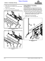
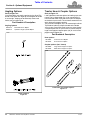
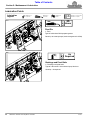
Spring Adjustment
Refer to Figure 2-3:
Over time and use, the springs on the Snow Trip Blade
can become stretched and/or loosened. Periodically
check to see if springs (#5) on the Snow Trip Blade are
loose. Tighten 2 nuts (#1) on eye bolt (#4) so
that the spring is tight and not loose. Adding extra flat
washers (#2) to the existing flat washer (#3) may be
necessary to stretch the springs tight.
74867
2
1
4
3
Spring Adjustment
Figure 2-3
4
5
3
2
1
74868
Factory set at 1/4".
Adjust to preference based on the tractor being used.
1/4" = 250 lbs (110 kg) of break out force
1" = 300 lbs (140 kg) of break out force
1 1/2" Max = 400 lbs (180 kg) of break out force
74880
Page is loading ...
Page is loading ...
Page is loading ...
Page is loading ...
Page is loading ...
Page is loading ...
Page is loading ...
Page is loading ...
Page is loading ...
Page is loading ...
Page is loading ...
Page is loading ...
Page is loading ...
Page is loading ...
Page is loading ...
Page is loading ...
-
 1
1
-
 2
2
-
 3
3
-
 4
4
-
 5
5
-
 6
6
-
 7
7
-
 8
8
-
 9
9
-
 10
10
-
 11
11
-
 12
12
-
 13
13
-
 14
14
-
 15
15
-
 16
16
-
 17
17
-
 18
18
-
 19
19
-
 20
20
-
 21
21
-
 22
22
-
 23
23
-
 24
24
-
 25
25
-
 26
26
-
 27
27
-
 28
28
-
 29
29
-
 30
30
-
 31
31
-
 32
32
-
 33
33
-
 34
34
-
 35
35
-
 36
36


Land Pride STB05 Series User manual
- Type
- User manual
- This manual is also suitable for
Ask a question and I''ll find the answer in the document
Finding information in a document is now easier with AI
Related papers
-
 Land Pride RBT4096 User manual
-
 Land Pride RBT3596 User manual
-
Land Pride RBT40 Series Quick start guide
-
 Land Pride RBT40 User manual
-
 Land Pride WC1503 User manual
-
 Land Pride RC5020 User manual
-
 Land Pride RC5014 Offset User manual
-
 Land Pride RCR12 Series User manual
-
 Land Pride RCF3096 Series User manual
-
 Land Pride RB37 User manual


Other documents
-
Craftsman Lawn Tractor Snow Blade 14" High Manufacturer's Warranty
-
Brinly-Hardy PP-51BH User guide
-
Bercomac BBLST6 User manual
-
Meyer 09917 Operating instructions
-
Toro Pivot Pin Kit, TXL 2000 Tool Carrier Installation guide
-
-
-
-
-