Page is loading ...

Table of Contents
Cover photo may show optional equipment not supplied
with standard unit.
For an Operator’s Manual and Decal Kit in French or
Spanish Language, please see your Land Pride dealer.
Read the Operator’s Manual entirely. When you see this symbol,
the subsequent instructions and warnings are serious - follow
without exception. Your life and the lives of others depend on it!
!
Disc Harrows
DH1048, DH1060, DH1560, DH1572, DH1590, DH2572 & DH2596
322-013M
Operator’s Manual
Printed 12/7/18
17800

12/7/18DH1048, DH1060, DH1560, DH1572, DH1590, DH2572 & DH2596 Disc Harrows 322-013M
Machine Identification
Record your machine details in the log below. If you replace this manual, be sure to transfer this information to the new
manual.
If you, or the dealer, have added Options not originally ordered with the machine, or removed Options that were
originally ordered, the weights and measurements are no longer accurate for your machine. Update the record by
adding the machine weight and measurements provided in the Specifications & Capacities Section of this manual with
the Option(s) weight and measurements.
Dealer Contact Information
Model Number
Serial Number
Machine Height
Machine Length
Machine Width
Machine Weight
Delivery Date
First Operation
Accessories
Name:
Street:
City/State:
Telephone:
Email:
WARNING: Cancer and reproductive harm - www.P65Warnings.ca.gov
!
California Proposition 65

Table of Contents
© Copyright 2018 All rights Reserved
Land Pride provides this publication “as is” without warranty of any kind, either expressed or implied. While every precaution has been taken in the
preparation of this manual, Land Pride assumes no responsibility for errors or omissions. Neither is any liability assumed for damages resulting from the use
of the information contained herein. Land Pride reserves the right to revise and improve its products as it sees fit. This publication describes the state of this
product at the time of its publication, and may not reflect the product in the future.
Land Pride is a registered trademark.
All other brands and product names are trademarks or registered trademarks of their respective holders.
Printed in the United States of America.
12/7/18
DH1048, DH1060, DH1560, DH1572, DH1590, DH2572 & DH2596 Disc Harrows 322-013M
Table of Contents
Important Safety Information . . . . . . . . . . . . . 1
Safety at All Times . . . . . . . . . . . . . . . . . . . . . . . . . 1
Look for the Safety Alert Symbol . . . . . . . . . . . . . . . 1
Safety Labels . . . . . . . . . . . . . . . . . . . . . . . . . . . . . 4
Introduction . . . . . . . . . . . . . . . . . . . . . . . . . . . 6
Application . . . . . . . . . . . . . . . . . . . . . . . . . . . . . . . 6
Using This Manual . . . . . . . . . . . . . . . . . . . . . . . . . 6
Owner Assistance . . . . . . . . . . . . . . . . . . . . . . . . . . 6
Section 1: Assembly & Set-Up . . . . . . . . . . . . 8
Tractor Requirements . . . . . . . . . . . . . . . . . . . . . . . 8
Torque Requirements . . . . . . . . . . . . . . . . . . . . . . . 8
Dealer Assembly . . . . . . . . . . . . . . . . . . . . . . . . . . . 8
DH10 & DH15 Series . . . . . . . . . . . . . . . . . . . . . . 8
DH25 Series . . . . . . . . . . . . . . . . . . . . . . . . . . . . 9
Optional Equipment . . . . . . . . . . . . . . . . . . . . . . . . 10
Scrapers
DH15 & DH25 Series Only . . . . . . . . . . . . . . . . . 10
Center Sweep
DH15 & DH25 Series Only . . . . . . . . . . . . . . . . . 10
Tractor Hook-Up . . . . . . . . . . . . . . . . . . . . . . . . . . 11
Section 2: Operating Instructions . . . . . . . . . 12
Operator’s Responsibilities . . . . . . . . . . . . . . . . . . 12
Transporting . . . . . . . . . . . . . . . . . . . . . . . . . . . . . 12
Field Operation . . . . . . . . . . . . . . . . . . . . . . . . . . . 13
General Operating Instructions . . . . . . . . . . . . . . . 13
Section 3: Adjustments . . . . . . . . . . . . . . . . . 14
Disc Angling . . . . . . . . . . . . . . . . . . . . . . . . . . . . . 14
Disc Gang Lateral Adjustment . . . . . . . . . . . . . . . . 15
Front Disc Gangs on DH10 Series . . . . . . . . . . . 15
Front Disc Gangs on DH15 Series . . . . . . . . . . . 15
Front Disc Gangs on DH25 Series . . . . . . . . . . . 15
Rear Disc Gangs on DH10 Series . . . . . . . . . . . 15
Rear Disc Gangs on DH15 Series . . . . . . . . . . . 15
Rear Disc Gangs on DH25 Series . . . . . . . . . . . 15
Disc Leveling Front To Rear . . . . . . . . . . . . . . . 15
Disc Blade Replacement . . . . . . . . . . . . . . . . . . . . 15
Section 4: Accessories . . . . . . . . . . . . . . . . . 16
Electric Spin Spreader . . . . . . . . . . . . . . . . . . . . 16
Drag Harrow . . . . . . . . . . . . . . . . . . . . . . . . . . . 16
Seed Bed Roller . . . . . . . . . . . . . . . . . . . . . . . . . 16
Complete One Pass Seeding Application . . . . . . 17
Section 5: Maintenance . . . . . . . . . . . . . . . . . 18
General Maintenance Information . . . . . . . . . . . . . 18
Daily Operational Checks . . . . . . . . . . . . . . . . . . . 18
Lubrication . . . . . . . . . . . . . . . . . . . . . . . . . . . . . . 18
Long-Term Storage . . . . . . . . . . . . . . . . . . . . . . . . 18
Section 6: Specifications & Capacities . . . . . 19
Section 7: Features & Benefits . . . . . . . . . . . 22
Section 8: Troubleshooting . . . . . . . . . . . . . . 24
Section 9: Torque Values Chart . . . . . . . . . . . 26
Section 10: Warranty . . . . . . . . . . . . . . . . . . . 27

12/7/18
DH10 Series
DH15 & DH25
Series
Dealer QR Locator
The QR code below will link you
to available dealers for Land Pride
products.
Manual QR Locator
The QR (Quick Reference) codes on the cover and below will take you to the
Parts Manual. Download the appropriate App on your camera phone, open the
App, point your phone on the QR code, and take a picture.
See previous page for Table of contents.

Important Safety Information
12/7/18
1
Important Safety Information
Listed below are common practices that may or may not be applicable to the products
described in this manual.
Tractor Shutdown & Storage
If engaged, disengage power
take-off.
Park on solid, level ground and
lower implement to ground or onto
support blocks.
Put tractor in park or set park
brake, turn off engine, and remove
switch key to prevent unauthorized
starting.
Relieve all hydraulic pressure to
auxiliary hydraulic lines.
Wait for all components to stop
before leaving operator’s seat.
Use steps, grab-handles and
anti-slip surfaces when stepping
on and off the tractor.
Detach and store implement in an
area where children normally do
not play. Secure implement using
blocks and supports.
OFF
REMOVE
Look for the Safety Alert Symbol
The SAFETY ALERT SYMBOL indicates there is a
potential hazard to personal safety involved and extra
safety precaution must be taken. When you see this
symbol, be alert and carefully read the message that
follows it. In addition to design and configuration of
equipment, hazard control, and accident prevention are
dependent upon the awareness, concern, prudence, and
proper training of personnel involved in the operation,
transport, maintenance, and storage of equipment.
Safety Precautions for
Children
Tragedy can occur if the operator
is not alert to the presence of
children. Children generally are
attracted to implements and their
work.
Never assume children will remain
where you last saw them.
Keep children out of the work area
and under the watchful eye of a
responsible adult.
Be alert and shut the implement
and tractor down if children enter
the work area.
Never carry children on the tractor
or implement. There is not a safe
place for them to ride. They may
fall off and be run over or interfere
with the control of the power
machine.
Never allow children to operate the
power machine, even under adult
supervision.
Never allow children to play on the
power machine or implement.
Use extra caution when backing
up. Before the tractor starts to
move, look down and behind to
make sure the area is clear.
Safety at All Times
Careful operation is your best
assurance against an accident.
All operators, no matter how much
experience they may have, should
carefully read this manual and
other related manuals, or have the
manuals read to them, before
operating the power machine and
this implement.
Thoroughly read and understand
the “Safety Label” section. Read
all instructions noted on them.
Do not operate the equipment
while under the influence of drugs
or alcohol as they impair the ability
to safely and properly operate the
equipment.
The operator should be familiar
with all functions of the tractor and
attached implement and be able to
handle emergencies quickly.
Make sure all guards and shields
appropriate for the operation are in
place and secured before
operating implement.
Keep all bystanders away from
equipment and work area.
Start tractor from the driver’s seat
with hydraulic controls in neutral.
Operate tractor and controls from
the driver’s seat only.
Never dismount from a moving
tractor or leave tractor unattended
with engine running.
Do not allow anyone to stand
between tractor and implement
while backing up to implement.
Keep hands, feet, and clothing
away from power-driven parts.
While transporting and operating
equipment, watch out for objects
overhead and along side such as
fences, trees, buildings, wires, etc.
Do not turn tractor so tight as to
cause hitched implement to ride
up on the tractor’s rear wheel.
Store implement in an area where
children normally do not play.
When needed, secure attachment
against falling with support blocks.
Be Aware of
Signal Words
A signal word designates a degree or
level of hazard seriousness. The
signal words are:
Indicates a hazardous situation that, if
not avoided, will result in death or
serious injury.
Indicates a hazardous situation that, if
not avoided, could result in death or
serious injury.
Indicates a hazardous situation that, if
not avoided, may result in minor or
moderate injury.
WARNING
CAUTION
!
!
!
DANGER
!

Important Safety Information
12/7/18
2
Listed below are common practices that may or may not be applicable to the products
described in this manual.
Practice Safe Maintenance
Understand procedure before doing
work. Refer to the Operator’s
Manual for additional information.
Work on a level surface in a clean
dry area that is well-lit.
Lower implement to the ground and
follow all shutdown procedures
before leaving the operator’s seat to
perform maintenance.
Do not work under any hydraulic
supported equipment. It can settle,
suddenly leak down, or be lowered
accidentally. If it is necessary to
work under the equipment, securely
support it with stands or suitable
blocking beforehand.
Use properly grounded electrical
outlets and tools.
Use correct tools and equipment for
the job that are in good condition.
Allow equipment to cool before
working on it.
Disconnect battery ground cable (-)
before servicing or adjusting
electrical systems or before welding
on implement.
Inspect all parts. Make certain
parts are in good condition &
installed properly.
Replace parts on this implement
with genuine Land Pride parts only.
Do not alter this implement in a way
which will adversely affect its
performance.
Do not grease or oil implement
while it is in operation.
Remove buildup of grease, oil, or
debris.
Always make sure any material and
waste products from the repair and
maintenance of the implement are
properly collected and disposed.
Remove all tools and unused parts
before operation.
Do not weld or torch on galvanized
metal as it will release toxic fumes.
Use A Safety Chain
A safety chain will help control
drawn machinery should it
separate from the tractor drawbar.
Use a chain with the strength
rating equal to or greater than the
gross weight of the towed
implement.
Attach the chain to the tractor
drawbar support or other specified
anchor location. Allow only
enough slack in the chain to
permit turning.
Always hitch the implement to the
machine towing it. Do not use the
safety chain tow the implement.
Transport Safely
Comply with federal, state, and
local laws.
Use towing vehicle and trailer of
adequate size and capacity. Secure
equipment towed on a trailer with
tie downs and chains.
Sudden braking can cause a towed
trailer to swerve and upset. Reduce
speed if towed trailer is not
equipped with brakes.
Avoid contact with any overhead
utility lines or electrically charged
conductors.
Always drive with load on end of
loader arms low to the ground.
Always drive straight up and down
steep inclines with heavy end of a
tractor with loader attachment on
the “uphill” side.
Engage park brake when stopped
on an incline.
Maximum transport speed for an
attached equipment is 20 mph. DO
NOT EXCEED. Never travel at a
speed which does not allow
adequate control of steering and
stopping. Some rough terrains
require a slower speed.
As a guideline, use the following
maximum speed weight ratios for
attached equipment:
20 mph when weight of attached
equipment is less than or equal
to the weight of machine towing
the equipment.
10 mph when weight of attached
equipment exceeds weight of
machine towing equipment but
not more than double the weight.
IMPORTANT: Do not tow a load
that is more than double the weight
of the vehicle towing the load.
Tire Safety
Tire changing can be dangerous
and must be performed by
trained personnel using the
correct tools and equipment.
Always maintain correct tire
pressure. Do not inflate tires
above recommended pressures
shown in the Operator’s Manual.
When inflating tires, use a clip-on
chuck and extension hose long
enough to allow you to stand to
one side and NOT in front of or
over the tire assembly. Use a
safety cage if available.
Securely support the implement
when changing a wheel.
When removing and installing
wheels, use wheel handling
equipment adequate for the
weight involved.
Make sure wheel bolts have been
tightened to the specified torque.

Important Safety Information
12/7/18
3
Listed below are common practices that may or may not be applicable to the products
described in this manual.
Avoid High
Pressure Fluids Hazard
Escaping fluid under pressure can
penetrate the skin causing serious
injury.
Before disconnecting hydraulic
lines or performing work on the
hydraulic system, be sure to
release all residual pressure.
Make sure all hydraulic fluid
connections are tight and all
hydraulic hoses and lines are in
good condition before applying
pressure to the system.
Use a piece of paper or
cardboard, NOT BODY PARTS, to
check for suspected leaks.
Wear protective gloves and safety
glasses or goggles when working
with hydraulic systems.
DO NOT DELAY. If an accident
occurs, see a doctor familiar with
this type of injury immediately. Any
fluid injected into the skin or eyes
must be treated within
a few hours or
gangrene may
result.
Wear Personal Protective
Equipment (PPE)
Wear protective clothing and
equipment appropriate for the job
such as safety shoes, safety
glasses, hard hat, and ear plugs.
Clothing should fit snug without
fringes and pull strings to avoid
entanglement with moving parts.
Prolonged exposure to loud noise
can cause hearing impairment or
hearing loss. Wear suitable
hearing protection such as
earmuffs or earplugs.
Operating equipment safely
requires the operator’s full
attention. Avoid wearing
headphones while operating
equipment.
Use Seat Belt and ROPS
Land Pride recommends the use
of a CAB or roll-over-protective-
structures (ROPS) and seat belt
in almost all power machines.
Combination of a CAB or ROPS
and seat belt will reduce the risk
of serious injury or death if the
power machine should be upset.
If ROPS is in the locked-up
position, fasten seat belt snugly
and securely to help protect
against serious injury or death
from falling and machine overturn.
Keep Riders Off
Machinery
Never carry riders on tractor or
implement.
Riders obstruct operator’s view
and interfere with the control of
the power machine.
Riders can be struck by objects or
thrown from the equipment.
Never use tractor or implement to
lift or transport riders.
Avoid Underground
Utilities
Dig Safe, Call 811 (USA).
Always contact your local utility
companies (electrical, telephone,
gas, water, sewer, and others)
before digging so that they may
mark the location of any
underground services in the area.
Be sure to ask how close you can
work to the marks they positioned.
Prepare for Emergencies
Be prepared if a fire starts.
Keep a first aid kit and fire
extinguisher handy.
Keep emergency numbers for
doctor, ambulance, hospital, and
fire department near phone.
911
Use Safety
Lights and Devices
Slow moving tractors, skid steers,
self-propelled machines, and towed
equipment can create a hazard
when driven on public roads. They
are difficult to see, especially at
night. Use the Slow Moving Vehicle
sign (SMV) when on public roads.
Flashing warning lights and turn
signals are recommended
whenever driving on public roads.

Important Safety Information
Table of Contents
DH1048, DH1060, DH1560, DH1572, DH1590, DH2572 & DH2596 Disc Harrows 322-013M 12/7/18
4
Safety Labels
Your Disc Harrow comes equipped with all safety labels in
place. They were designed to help you safely operate your
equipment. Read and follow their directions.
1. Keep all safety labels clean and legible.
2. Refer to this section for proper label placement. Replace
all damaged or missing labels. Order new labels from your
nearest Land Pride dealer. To find your nearest dealer,
visit our dealer locator at www.landpride.com.
3. Some new equipment installed during repair requires
safety labels to be affixed to the replaced component as
specified by Land Pride. When ordering new components
make sure the correct safety labels are included in the
request.
4. Refer to this section for proper label placement. To install
new labels:
a. Clean surface area where label is to be placed.
b. Spray soapy water onto the cleaned area.
c. Peel backing from label and press label firmly onto the
surface.
d. Squeeze out air bubbles with edge of a credit card or
with a similar type of straight edge.
818-719C
Caution General
DH10 Series
23755
23753
DH15 & DH25 Series
17800
Important Safety Information

Important Safety Information
Table of Contents
DH1048, DH1060, DH1560, DH1572, DH1590, DH2572 & DH2596 Disc Harrows 322-013M12/7/18
5
838-093C
Warning Sharp Object
838-614C
2" x 9" Red Reflector (2 places on DH1590 & DH2596)
858-095C
2" x 4 1/2" Red Reflector (2 places on DH1048, DH1060,
DH1560, DH1572, & DH2572)
17801
DH10 & DH15 Series
DH25 Series
23753
25847
Warning Decals on end of Disc Gangs are for Set-up Only.
Location may vary from gang to gang.
The customer is not required to maintain them once worn off.

Introduction
Table of Contents
DH1048, DH1060, DH1560, DH1572, DH1590, DH2572 & DH2596 Disc Harrows 322-013M 12/7/18
6
Using This Manual
•
This Operator’s Manual is designed to help familiarize
the operator with safety, assembly, operation,
adjustments, troubleshooting, and maintenance. Read
this manual and follow the recommendations to help
ensure safe and efficient operation.
• The information contained within this manual was
current at the time of printing. Some parts may change
slightly to assure you of the best performance.
• To order a new Operator’s or Parts Manual, contact
your authorized dealer. Manuals can also be
downloaded, free-of-charge, from our website at
www.landpride.com
Terminology
“Right” or “Left” as used in this manual is determined by
facing forward in the direction the machine will operate
while in use unless otherwise stated.
Definitions
Owner Assistance
The dealer should complete the Online Warranty
Registration at the time of purchase. This information is
necessary to provide you with quality customer service.
The parts on your Disc Harrow have been specially
designed by Land Pride and should only be replaced with
genuine Land Pride parts. Contact a Land Pride dealer if
customer service or repair parts are required. Your Land
Pride dealer has trained personnel, repair parts, and
equipment needed to service the implement.
IMPORTANT: A special point of information related
to the following topic. Land Pride’s intention is this
information must be read & noted before continuing.
NOTE: A special point of information that the
operator should be aware of before continuing.
Land Pride welcomes you to the growing family of new
product owners. This Disc Harrow has been designed
with care and built by skilled workers using quality
materials. Proper assembly, maintenance, and safe
operating practices will help you get years of satisfactory
use from this machine.
Application
The DH10 Series Economy Disc Harrows are designed
to open up and break up the soil surface and to prepare
the soil for seedbed or planting preparation. The DH10
Series Discs are adapted for Category 1 three-point hitch
mounting on tractors in the 20-40 horsepower range, and
are Quick Hitch adaptable. The forward gang has
aggressive notched discs while the rear gang has a
choice of notched or smooth discs to quickly break up
and evenly redistribute the finely cultivated topsoil. The
DH10 Series Land Pride Discs have applications in
homeowner landscaping, smaller nurseries, gardens,
smaller hobby farms, wild game food plots, and medium
duty residential use. The 48" Disc Harrow features 16"
disks, while the 60" offers 16" or 18".
The DH15 Series Disc Harrows are designed to
breakup and redistribute the soil surface in preparation of
seedbeds for planting operations. The DH15 Series
Discs are adapted for Category 1 three-point hitch on
tractors in the 25-65 horsepower range, and are Quick
Hitch adaptable. Disc gangs can be ordered with smooth
or notched disc gang arrays for lighter or more
aggressive applications based on customer needs. The
DH15 Series Disc Harrows have applications in
commercial landscaping, nurseries, large gardens,
farms, and municipal beautification programs.
The DH25 Series Disc Harrows are designed to
breakup and redistribute the soil surface in preparation of
seedbed and field planting operations. The DH25 Series
Discs are adapted for category 1 and 2 three-point hitch
on tractors in the 35-100 horsepower range, and are
Quick Hitch adaptable. Disc gangs can be ordered with
smooth or notched disc gang arrays for lighter or more
aggressive applications and this series does offer 20"
diameter or larger 22" diameter discs to meet specific
customer needs. The DH25 Series Disc Harrows have
applications in commercial landscaping, construction,
farms, ranches, and municipal maintenance programs.
See “Specifications & Capacities” on page 19 and
“Features & Benefits” on page 22 for additional
information and performance enhancing options.
Introduction

Introduction
Table of Contents
DH1048, DH1060, DH1560, DH1572, DH1590, DH2572 & DH2596 Disc Harrows 322-013M12/7/18
7
Serial Number
For quick reference and prompt service, record model
and serial number on the inside cover page and again on
the warranty page. Always provide model number and
serial number when ordering parts and in all
correspondences with your Land Pride dealer. For
location of your serial number plate, see Figure 1.
Serial Number Plate Location
Figure 1
Further Assistance
Your dealer wants you to be satisfied with your new Disc
Harrow. If for any reason you do not understand any part
of this manual or are not satisfied with the service
received, the following actions are suggested:
1. Discuss any problems you have with your implement
with your dealership service personnel so they can
address the problem.
2. If you are still not satisfied, seek out the owner or
general manager of the dealership, explain the
question/problem, and request assistance.
3. For further assistance write to:
Land Pride Service Department
1525 East North Street
P.O. Box 5060
Salina, Ks. 67402-5060
E-mail address
lpser[email protected]
17800

Section 1: Assembly & Set-Up
Table of Contents
DH1048, DH1060, DH1560, DH1572, DH1590, DH2572 & DH2596 Disc Harrows 322-013M 12/7/18
8
Section 1: Assembly & Set-Up
Dealer Assembly (DH1560 Shown)
Figure 1-1
18764
Dealer Assembly
DH10 & DH15 Series
!
WARNING
To avoid serious injury or death:
Be careful when working with disc blades as the edges are
sharp. Wear gloves when working around disc blades. Keep
others away.
Refer to Figure 1-1
1. Unpack Disc Harrow from shipping crate.
2. Attach 3-Point straps (#1 & #2) to front lower lifting
lugs using 7/8" hitch pins (#3), lock washers (#4),
and 7/8" -14 hex nuts (#5). Do not tighten.
3. Attach 3-Point brace (#6) to the harrow’s center beam
with 3/4" -10 x 4 1/2" GR5 hex head cap
screw (#7) and 3/4" locknut (#8). Do not tighten.
4. Insert 3/4" -10 x 4 1/2" hex head bolt (#9) through the
left side of 3-Point brace (#6), left 3-Point strap (#1),
spacer (#10), right 3-Point strap (#2), and right side
of 3-Point brace (#6). Secure bolt with 3/4" lock
nut (#5). Do not tighten.
5. Insert 3/4" clevis pin (#12) through upper holes in
3-Point straps (#1 & #2). Secure clevis pin with
hairpin cotter (#13).
6. Tighten all attaching hardware to the correct torque.
Tractor Requirements
Tractor 3-Point hitch Category and horsepower should
match your Disc Harrow Series.
• DH10 Series
3-Point Hitch. . . . . . . Category 1
Horsepower . . . . . . . 20-40 horsepower
• DH15 Series
3-Point Hitch. . . . . . . Category 1
Horsepower . . . . . . . 25-65 horsepower
• DH25 Series
3-Point Hitch. . . . . . . Category 1 & 2
Horsepower . . . . . . . 35-100 horsepower
!
WARNING
To avoid serious injury or death:
Lightweight tractors with rear attached implements may need
weights added to the front to maintain steering control.
Consult your tractor Operator’s Manual to determine proper
weight requirements and maximum weight limitations.
Torque Requirements
Refer to “Torque Values Chart” on page 26 to
determine correct torque values for common bolts. See
“Additional Torque Values” at bottom of chart for
exceptions to standard torque values.

Section 1: Assembly & Set-Up
Table of Contents
DH1048, DH1060, DH1560, DH1572, DH1590, DH2572 & DH2596 Disc Harrows 322-013M12/7/18
9
Dealer Assembly (DH2572 Shown)
Figure 1-2
18764
4. Insert swing arms (#6) through slots in
mainframe (#7). Re-install 3/4"-10 x 5" GR5
bolts (#10), locknuts (#12), spacers (#2), and bottom
brackets (#4) as shown.
5. Assemble disc gangs (#9) to main frame (#7) with
5/8" u-bolts (#14) and hex flange locknuts (#13). See
“Disc Gang Lateral Adjustment” on page 15 for
proper spacing.
6. Tighten hex flange locknuts (#13) to the correct
torque.
7. Install plastic end caps (#15) in swing arms (#6).
IMPORTANT: The next procedure will require lifting
mainframe frame (#7). A forklift or adequate lifting
device is recommended.
DH25 Series
Refer to Figure 1-2:
!
WARNING
To avoid serious injury or death:
Be careful when working with disc blades as the edges are
sharp. Wear gloves when working around disc blades. Keep
others away.
1. Unpack Disc Harrow from shipping crate.
2. Assemble 3-Point hitch as shown in Figure 1-2.
a. Align upper straps (#3) and rear brace (#8) as
shown.
b. Place spacer (#1) between upper straps (#3).
Secure spacer with 3/4"-10 x 5" GR5 bolt (#10)
and locknut (#12).
3. Remove bolts (#10), locknuts (#12), spacers (#2),
and bottom brackets (#4).

Section 1: Assembly & Set-Up
Table of Contents
DH1048, DH1060, DH1560, DH1572, DH1590, DH2572 & DH2596 Disc Harrows 322-013M 12/7/18
10
Scrapers Assembly
Figure 1-3
Center Sweep Assembly
Figure 1-4
19759
20562
Optional Equipment
Scrapers
DH15 & DH25 Series Only
Refer to Figure 1-3:
Install Scraper Assemblies (#1)
and (#2) using instruction manual
No. 322-042M included with scraper
kit.
Center Sweep
DH15 & DH25 Series Only
Refer to Figure 1-4:
Assemble Center Sweep to the
center tube of the Disc Harrow
Frame.
1. Clamp sweep arm (#8) to center
frame with spring bracket (#1),
two 5/8"-11 u-bolts (#6), and
5/8"-11 flange locknuts (#4).
2. Tighten hex flange locknuts (#4)
to the correct torque.
3. Attach 9" cultivator sweep (#7) to
sweep arm (#8) with 7/16-14
GR5 plow bolts (#2), lock
washer (#5), and 7/16"-14 hex
nuts (#3).
4. Tighten 7/16" hex nuts to the
correct torque.

Section 1: Assembly & Set-Up
Table of Contents
DH1048, DH1060, DH1560, DH1572, DH1590, DH2572 & DH2596 Disc Harrows 322-013M12/7/18
11
Tractor Hook-Up
!
DANGER
To avoid serious injury or death:
A crushing hazard exists while hooking-up and unhooking
implement. Keep people and animals away while backing-up
to implement or pulling away from implement. Do not operate
hydraulic controls while a person or animal is directly behind
the power machine or near the implement.
NOTE: Land Pride’s Quick Hitch can be attached to
the tractor to provide quick and easy 3-point hook-
up and detachment. See your nearest Land Pride
dealer to purchase a Quick-Hitch.
Refer to Figure 1-5:
1. Check tractor draw bar to make certain it will not
interfere with raising and lowering the Disc Harrow.
Move draw bar ahead or remove if required. Draw bar
should also be rechecked for clearance when raising
and lowering the unit for the first time.
2. Align lower link arms of tractor to hitch pins (#1) on
Disc Harrow. Insert lower hitch pins into hitch holes n
lower 3-point lift arms and secure in place with
linchpins (#2) (supplied by customer).
3. Attach tractor top center link to upper hitch of Disc
Harrow with hitch pin (#3) and secure with hairpin
cotter (#4).
4. Use lower bushing “A” when using a Cat.1 Quick Hitch
for tractor hook-up.
Tractor Hook-Up
Figure 1-5
17809
A
17809

Section 2: Operating Instructions
Table of Contents
DH1048, DH1060, DH1560, DH1572, DH1590, DH2572 & DH2596 Disc Harrows 322-013M 12/7/18
12
Section 2: Operating Instructions
Operator’s Responsibilities
Hazard control and accident prevention are dependent
upon the awareness, concern, prudence, and proper
training involved in the operation, transport, storage, and
maintenance of the Disc Harrow. Therefore, it is
absolutely essential that no one operates the harrow
unless they are age 16 or older and have read, fully
understood, and are totally familiar with the Operator’s
Manual. Make sure the operator has paid particular
attention to:
• Important Safety Information, page 1
• Section 1: Assembly & Set-Up, page 8
• Section 2: Operating Instructions, page 12
• Section 3: Adjustments, page 14
• Section 5: Maintenance, page 18
Perform the following inspections before using your Disc
Harrow.
!
DANGER
To avoid serious injury or death:
Do not allow anyone near the tractor or implement while
operating. Stop operation if bystanders are too close. They
can be hit by flying projectiles, become entangled in the
equipment, or ran over.
!
WARNING
To avoid serious injury or death:
• Allow only persons to operate this implement who have
fully read and comprehended this manual, who have been
properly trained in the safe operation of this implement, and
who are age 16 or older. Serious injury or death can result
from the inability to read, understand, and follow
instructions provided in this manual.
• Never carry riders on the implement or tractor. Riders can
obstruct the operator’s view, interfere with control of the
equipment, be pinched by moving components, become
entangled in rotating components, be struck by objects, be
thrown or fall from the equipment, etc.
• Do not use implement to lift objects; to pull objects such as
fence posts, stumps, etc; or to push objects. The unit is not
designed or guarded for these uses.
Operating Checklist
Check Ref.
Read “Important Safety Information” 1
Read all of the tractor hook-up and preparation
instructions.
11
Read “Operating Instructions” 12
Check harrow initially and periodically for
loose bolts & pins. Pay special attention to disc
gang hanger bolts and axle nuts.
Refer to Torque values Chart for torque values.
26
• Do not alter implement or replace parts on the implement
with other brands. Other brands may not fit properly or
meet OEM (Original Equipment Manufacturer)
specifications. They can weaken the integrity and impair the
safety, function, performance, and life of the implement.
Replace parts only with genuine OEM parts.
• Perform scheduled maintenance. Check for loose
hardware, missing parts, broken parts, structural cracks,
and excessive wear. Make repairs before putting implement
back into service. Serious breakdowns can result in injury
or death.
• Keep everyone away from the Disc Harrow while raising,
lowering, and transporting the implement to protect against
falling blade hazard.
• Never make contact with underground utilities such as
electrical power lines, gas lines, phone lines, etc. They can
cause serious injury or death from electrocution, explosion,
or fire. If in doubt, call 811 (USA) before digging so that
they can mark the location of underground services in the
area. For contact information, see Dig Safe in the
“Important Safety Information” starting on page 1.
Transporting
!
WARNING
To avoid serious injury or death:
When traveling on public roads, use LED lights, slow moving
vehicle sign, clean reflectors, and other adequate devices to
warn operators in other vehicles of your presence. If
implement blocks visibility of slow moving vehicle sign,
relocate sign so it is visible from the back at all times. Always
comply with all federal, state, and local laws.
1. Lift Disc Harrow as high as possible to make sure it
clears the ground in transportation.
2. Never transport with negative or insufficient front
tractor weight. Doing so can result in loss of steering
control. If needed, add ballast to the tractor. Refer to
tractor Operator’s Manual for recommendations.
3. When traveling on roadways, transport in such a way
that faster moving vehicles may pass you safely.
4. Do not lower unit while transporting on pavement,
blacktop or road. Damage to unit and/or road may
occur.
5. Select a safe ground travel speed when transporting
from one area to another.
6. Be sure to reduce tractor ground speed when
turning; and, leave enough clearance so the Disc
Harrow does not contact obstacles such as buildings,
trees, or fences.
7. When traveling over rough or hilly terrain, shift tractor
to a lower gear.
IMPORTANT: Make sure all safety labels are in their
proper location and in good condition before
operation. Follow all directions on the safety labels.

Section 2: Operating Instructions
Table of Contents
DH1048, DH1060, DH1560, DH1572, DH1590, DH2572 & DH2596 Disc Harrows 322-013M12/7/18
13
Field Operation
!
WARNING
To avoid serious injury or death:
Be careful when working with disc blades as the edges are
sharp. Wear gloves when working around disc blades. Keep
others away.
1. After initial adjustments have been made with tractor
hooked to the Disc Harrow, you are ready to start
discing.
2. Lower Disc Harrow to the ground and start moving
forward. Your travel speed will be determined by soil
conditions. You may find that you will want to change
the disc angle to do the job right. Refer to “Disc
Angling” on page 14 for detailed instructions.
3. Always lift unit out of ground when turning.
4. Do not disc in reverse (traveling backwards). The
Disc Harrow is designed for working soil while
traveling forward only. Damage to the harrow may
occur. Recommended procedure for working corners
or other tight places is:
a. Lift unit up.
b. Back unit into the corner or other tight areas.
c. Lower unit down and proceed forward with disc in
the ground.
5. Refer to Figure 2-1: Always cross steep ditches and
banks on the diagonal! Never cross straight across!
Damage to the disc and/or tractor may occur while
crossing straight across.
Figure 2-1
IMPORTANT: The harrow can be damaged if it is not
lifted out of the ground before making sharp turns
and before backing-up.
IMPORTANT: do not cross straight across steep
ditches and banks. Damage to the disc and/or
tractor may occur while crossing straight across.
Ditch / Bank
Ditch / Bank
Incorrect Crossing (Straight Across)
Correct Crossing (On the diagonal)
General Operating Instructions
Before putting your Land Pride Disc Harrow into service
you must thoroughly review the Operator’s Manual. Once
you have read the Operator’s Manual and properly
mounted your Land Pride Disc Harrow on your tractor,
you should be ready to head for the work site. You should
have already removed any sizable tree limbs, rocks, or
debris from this area. Do not attempt to disc wet or mucky
soil and all areas should be well drained and capable of
being walked on without having the soil stick to your
shoes.
Discing action will commence as soon as the unit
touches the ground and tractor begins to move forward.
Your travel speed forward will be determined by soil
conditions and available tractor horsepower. Never try to
disc in reverse and when you reach the end of a pass,
pick the unit up before turning. Trying to turn sharply with
the unit in the ground will cause extreme side loading on
the discs and may cause damage. Making disc gang
adjustments is relatively easy by raising the disc off of the
ground, placing safety blocks under the frame, pulling the
locking pin, making the required adjustment, and then
reverse the process till you are back in action. The
operator’s manual illustrates this process very clearly.
Ground conditions and the finish you require will
determine how you position the angles of your front and
rear disc gangs. Both of the front and rear disc gangs
have four angle adjustment positions. The best ground
finish will usually be achieved when the rear gang is set
at a slightly lesser angle than the front gang. The more
aggressive you set the angle of the gangs, the more
aggressive the cutting action in the soil profile will be. The
more aggressive the cutting action is, the more
horsepower will be required to pull your unit. Achieving
the desired effect may require a little experimentation in
your given conditions. If the soil is building up on or
sticking to your discs then the soil is too wet and discing
operations should be discontinued until the ground is dry
and more workable.
Once you are finished using your disc, park it on a dry
and level surface, clean it, and make it ready for the next
use. With a little practice you will be able to achieve
excellent results from your Land Pride Disc Harrow. See
“Features and Benefits” section or “Product
Specifications” for additional information and
performance enhancing options.

Section 3: Adjustments
Table of Contents
DH1048, DH1060, DH1560, DH1572, DH1590, DH2572 & DH2596 Disc Harrows 322-013M 12/7/18
14
Disc Adjustments
Figure 3-1
17867
Pin (#1) is secured with a ball- detent
on DH10 Series. All other Series uses
the hair pin cotter (#3) to secure the
pin.
Section 3: Adjustments
Disc Angling
Refer to Figure 3-1:
!
WARNING
To avoid serious injury or death:
• Always shut tractor down using “Tractor Shutdown
Procedure” provided in this manual before servicing,
adjusting, cleaning, or maintaining this implement.
• Properly block and secure disc in the raised position prior
to changing gang angles, gang position, disc replacement
or during maintenance. Keep feet out from under the disc
blades during adjustments or maintenance.
• Be careful when working with disc blades as the edges are
sharp. Wear gloves when working around disc blades. Keep
others away.
NOTE: The more angle you have on the disc, the more
aggressive the cut will be, and the more horsepower
will be required to pull your unit.
The Disc Harrow is designed with handles (#2) to make
disc gang angle adjustments easy. Adjust disc gangs as
follows:
• DH10 Series: Remove hitch pin (#1). Slide handle (#2)
to desired position and replace hitch pin.
• DH15 & DH25 Series: Remove hitch pin (#1) and hair
pin cotter (#3). Slide handle (#2) to desired position
and replace hitch pin and hair pin cotter.
NOTE: For a better ground finish, angle the rear
gangs at a lesser angle than the front gangs.
The front discs on all series have four angle
positions: (0, 7, 14, and 21 degrees.)
The rear discs on DH10 and DH15 Series have four
angle positions: (0, 7, 14, and 21 degrees.)
The rear discs on DH25 Series have three angle
positions: (7, 14, and 21 degrees.)

Section 3: Adjustments
Table of Contents
DH1048, DH1060, DH1560, DH1572, DH1590, DH2572 & DH2596 Disc Harrows 322-013M12/7/18
15
Disc Gang Lateral Adjustment
Refer to Figure 3-2:
Additional adjustments can be made by loosening
u-bolts (#1) and sliding disc gangs in or out to desired
position.
Disc Adjustments
Figure 3-2
Front Disc Gangs on DH10 Series
The recommended position for the front disc gangs (at
ground contact point) is 8 1/4" between inside gang disc
blades and equally spaced on either side of center frame
tube. Tighten u-bolts after adjustment.
Front Disc Gangs on DH15 Series
The recommended position for the front disc gangs (at
ground contact point) is 7 1/2" between inside gang disc
blades and equally spaced on either side of center frame
tube. Tighten u-bolts after adjustment.
Front Disc Gangs on DH25 Series
The recommended position for the front disc gangs (at
ground contact point) is 9 1/2" between inside gang disc
blades and equally spaced on either side of center frame
tube. Tighten u-bolts after adjustment.
Rear Disc Gangs on DH10 Series
The recommended position for the rear disc gangs (at
ground contact point) is 17 1/4" between inside disc
blades and equally spaced on either side of center frame
tube. Tighten u-bolts after adjustment.
NOTE: The rear discs should be centered between
the front discs for optimum performance.
17805
Rear Disc Gangs on DH15 Series
The recommended position for the rear disc gangs (at
ground contact point) is 15" between inside disc blades
and equally spaced on either side of center frame tube.
Tighten u-bolts after adjustment.
Rear Disc Gangs on DH25 Series
The recommended position for the rear disc gangs (at
ground contact point) is 17" between inside disc blades
and equally spaced on either side of center frame tube.
Tighten u-bolts after adjustment.
Disc Leveling Front To Rear
The truest way to level your disc from front to rear is to
observe behind the center of the Disc Harrow. In most
soil conditions, a slight ridge in the center is actually a
level operation. More air pockets will form where soil is
thrown against each other, causing a small ridge to from
that will disappear after a soaking rain.
1. If unit is leaving a significant ridge in the center,
raise disc rear gangs by shortening the center
3-Point link.
2. If unit is leaving a furrow (valley) in the center, lower
rear disc gangs by lengthening the center 3-Point
link.
3. See also Section 8: Troubleshooting for helpful
solutions to leveling the Disc Harrow.
Disc Blade Replacement
Refer to Figure 3-3:
When replacing notched disc blades, assemble disc
blades in a spiral pattern.
Disc Replacement (Spiral)
Figure 3-3
17802

Section 4: Accessories
Table of Contents
DH1048, DH1060, DH1560, DH1572, DH1590, DH2572 & DH2596 Disc Harrows 322-013M 12/7/18
16
Electric Spin Spreader
Refer to Figure 4-1:
The Land Pride Electric Spin Spreader is a highly
versatile package designed to plant or spread seeds,
fertilizer, lime, gypsum, and other soil conditioning
amendments at distances ranging from 4 ft. to 20 ft. It can
also be used in the off-season to spread sand or salt for
winter icing or slick snow conditions.
The unit has a 12 Volt remote tether control that can be
operated right from the driver seat to turn the spreader on
or off or to set the seed-gate opening to different
application rates.
The Spin Spreader has applications in overseeding of
pastures, grassy runways, open areas, roadsides,
medians, wild game food plots, hunting clubs, hunting
resorts, ranches, farms, game preserves, landscaping,
and hobby farming. It also works very well in gardens and
nurseries to incorporate fertilizer and pelletized gypsum
or lime as soil amendments.
Accessories are available for mounting the spreader to a
2" receiver hitch on a utility vehicle or to a Land Pride
Disc Harrow. A rear hitch can be attached to the Spin
Spreader mounting bracket for the Disc Harrow. The Disc
Harrow and Seed Bed Roller can then be hitched to the
rear hitch. See “Complete One Pass Seeding
Application” on page 17.
Electric Spin Spreader, Mounting Bracket & Rear Hitch
Figure 4-1
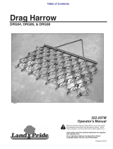
Drag Harrow
Refer to Figure 4-2:
The Land Pride Drag Harrows are designed for various
types of seedbed and ground preparations. They can be
used to smooth out freshly cultivated soil, work seed and
fertilizer into freshly cultivated soil or into turf and pasture
grass, fluff and level arenas, aerate soil for faster
dry-downtime, dethatch and aerate lawns and pastures,
break up aeration cores on turf surfaces, and groom
snow-packed ski resorts.
The Drag Harrow can also be used in tandem with Land
Pride’s Disc Harrow, Electric Spin Spreader, and Seed
Bed Roller to provide a highly efficient and complete
seeding application in one pass. See “Complete One
Pass Seeding Application” on page 17.
Rear Hitch
Spin Spreader
Mounting
25609
Drag Harrow (6’ x 4’ Shown)
Figure 4-2
Land Pride Drag Harrow Models
Model DRG04 . . . . . . . . . . . . . . . . 4 ft. wide x 4 ft. long
Model DRG06 . . . . . . . . . . . . . . . . 6 ft. wide x 4 ft. long
Model DRG08 . . . . . . . . . . . . . . . . 8 ft. wide x 4 ft. long
SBR72 Set-up for Pull Type Hook-Up
Figure 4-3
Seed Bed Roller
Refer to Figure 4-3:
The Land Pride SBR72 Three-point hitch or pull type
Seed Bed Roller has uses and applications in
landscaping, sports field maintenance, pasture
maintenance, professional turf care, general seeding,
and overseeding applications around home sites,
construction sites, horse paddocks, nurseries, sod farms,
and small farm or ranch operations. The SBR72 will
break up smaller clumps and dirt clods, while pressing
applied seed into firm contact with the soil profile for
greatly improved germination rates. The notched profile
of the roller also develops a pattern of uniformly spaced
mini-furrows that tend to hold seed and fertilizer in place.
These small furrows also retain essential moisture, and
resist erosion from the wind and runoff from applied
irrigation or rain. It can be pulled behind the Electric Spin
Spreader or behind any machine equipped with a
drawbar or receiver hitch. The hitch on the tongue can be
set-up as a clevis hitch or turned around for a ball hitch.
25611
25762
Section 4: Accessories
/