ESAB LAF 630/ LAF 800 / LAF 1250/ LAF 1600 User manual
- Category
- Welding System
- Type
- User manual

0740 801 008 2008--04--09
Valid from Serial NO 615
LAF 630/ 800/
1250/ 1600 DC
104
Service manual

-- 2 --
Rights reserved to al ter specifications without notice.
ENGLISH 3..............................................

ENGLISH
-- 3 --
TOCe
1 READ THIS FIRST 4..................................................
1.1 General 4..................................................................
1.2 Software versions 5.........................................................
1.3 Hardware versions 6.........................................................
2SAFETY 7...........................................................
3 COMPONENT DESCRIPTION (LAF 630/800/1250/1600) 9................
4 CONNECTION DIAGRAM (LAF 630) 10.................................
5 CONNECTION DIAGRAM (LAF 800) 12.................................
5.1 From serial no. 615 12........................................................
5.2 From serial no. 310 14........................................................
6 CONNECTION DIAGRAM (LAF 1250/ 1600) 16...........................
6.1 From serial no. 615 16........................................................
6.2 From serial no. 310 18........................................................
6.3 From serial no. 624 20........................................................
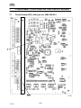
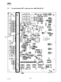
7 COMPONENT POSITIONS ON THE CIRCUIT BOARD 22..................
7.1 Circuit board (AP1) with part no: 0486 368 001 22................................
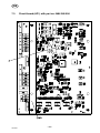
7.2 Circuit board (AP1) with part no: 0486 368 001A 23..............................
7.3 Circuit board (AP1) with part no: 0486 368 006 24................................
8 DESCRIPTION OF OPERATION 25.....................................
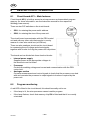
8.1 Circuit board AP1 -- Main features 25...........................................
8.2 Program monitoring 25........................................................
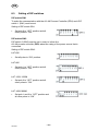
8.3 Setting of DIP switches 26.....................................................
9 MAINTENANCE (Diodes and Thyristors) 34.............................
9.1 Checking Diodes and Thyristors 34.............................................
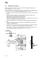
9.2 Fitting New Diodes 34........................................................
9.3 Fitting New Thyristors 35......................................................
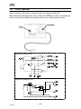
10 TEST DEVICE 36......................................................
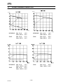
11 LOAD CHARACTERISTICS 37.........................................
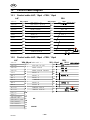
12 Control cable d iag ram 38.............................................
12.1 Control cable LAF / 12pol -- PEH / 12pol 38......................................
12.2 Control cable LAF / 28pol -- PEH / 12pol 38......................................
12.3 Control cable LAF / 28pol -- PEI / 23pol 39.......................................
CONNECTION INSTRUCTION 40..........................................
SPARE PARTS LIST 45...................................................

-- 4 --
fza1d1ea
1 READ THIS FIRST
1.1 General
This service manual is intended for use by technicians with electrical/electronic
training, for help in connection with fault--tracing and/or repair.
Use the connection diagram as a form of index for the description of operation and
the component description.
The circuit boar d is divided into numbered blocks, which are described individually in
more detail in the description of operation.
All component names in the connection diagram are listed in the component
description.
Note that there are different connection diagrams valid for different serial numbers.
This manual contains details of all design changes that have been made up to and
including March 2007.
For further information see the instruction manuals for LAF.
Welding power source: Instruction manual, order number:
LAF 630 0449 013 xxx
LAF 800 0449 014 xxx
LAF 1250 0449 015 xxx
LAF 1600 0449 017 xxx
GB

-- 5 --
fza1d1ea
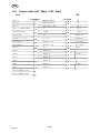
1.2 Software versions
From production start 97.07.04
LAF/TAF program (Flash, IC 6) 486525880
LAF/TAF 1.00A
From 99.01.01
LAF/TAF program (Flash, IC 6) 486525880
LAF/TAF 2.0
Strip welding and ESW welding.
Stainless steel setting. If this function is needed the power source board
486367001A in the LAF must be used.
Inch conversion.
From 00.02.29
LAF/TAF program (Flash, IC 6) 486525880
LAF/TAF 2.1
Improved wire creep speed LAF 1000ES
From 00.10.04
LAF/TAF program (Flash, IC 6) 486525880
LAF/TAF 2.4
Improved welding starts and welding
Safer detection of arc strike.
Changed sequence of weld start.
Faster engagement of the regulators.
Modified voltage regulation.
From 02.11.15
LAF/TAF program (Flash, IC 6) 486525880
LAF/TAF 4.0
Improved welding performance, better regulators.
Improved arc--ignition.
Parallel connection of LAF
TAF 800 60% duty factor
Complete support for Weldoc. (Not in the Chinese version)
Gauging process added.
Calibration function. (Not in the Chinese version)
Program version 4.0 or 4.0C is needed.
From 03.04.14
LAF/TAF program (Flash, IC 6) 486525880
LAF/TAF 4.01
Increased wire creep speed.
Voltage regulations for analogue interface (PEI).
Program version from PEH 4.0, PEH 4.0C is needed.
From 04.01.01
LAF/TAF program (Flash, IC 6) 486525880
LAF/TAF 4.2
Added new alarm.
Improved regulation.
Program version from PEH 4.0, PEH 4.0C is needed.
GB

-- 6 --
fza1d1ea
From 05.01.01
LAF/TAF program (Flash, IC 6) 486525880
LAF/TAF 4.3
Improved welding, analogue Interface.
Program version from PEH 4.0, PEH 4.0C is needed.
From 06.10.01
LAF/TAF program (Flash, IC 6) 486525880
LAF/TAF 5.0
Changed regulation, improved with dynamic characteristic.
Program version from PEH 5.0, PEH 5.0C is needed.
Require new hardware 486367008 for LAF.
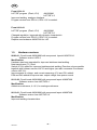
1.3 Hardware versions
98.09.01 Circuit board 486368880 with component layout 496367001A
Software version LAF2.0
Modification:
Hardware has been upgraded for improved stainless steel welding.
New transformer (T1) used.
Switch (IC 30) added for improved stainless steel welding (Function only accessible
together with software version LAF2.0 and higher (see also comments for software
version LAF 2.0).
Improvements in voltage-- and current measuring (C11 and C21 added).
D39 and D40 added to improve max. output voltage from power source
02.12.20 Circuit board 486368880 with component layout 496367006
Software version from LAF/TAF2.4
Modification:
Added new reference, 0--10 V, for analogue reference.
06.10.01 Circuit board 486368880 with component layout 486367008
Software version from LAF/TAF 5.0
Modification:
Improved welding characteristics.
GB

-- 7 --
fza1safeE
2SAFETY
Users of ESAB welding equipment have the ultimate responsibility for ensuring that anyone who
works on or near the equipment observes all the relevant safety precautions. Safety precautions
must meet the requirements that apply to this type of welding equipment. The following recommen-
dations should be observed in addition to the standard regulations that apply to the workplace.
All work must be carried out by trained personnel well--acquainted with the operation of the welding
equipment. Incorrect operation of the equipment may lead to hazardous situations which can result
in injury to the operator and damage to the equipment.
1. Anyone who uses the welding equipment must be familiar with:
S its operation
S location of emergency stops
S its function
S relevant safety precautions
S welding
2. The operator must ensure that:
S no unauthorised person is stationed within the working area of the equipment when it is
started up.
S no--one is unprotected when the arc is struck
3. The workplace must:
S be suitable for the purpose
S be free from draughts
4. Personal safety equipment
S Always wear recommended personal safety equipment, such as safety glasses, flame--proof
clothing, safety gloves.
S Do not wear loose--fitting items, such as scarves, bracelets, rings, etc., which could become
trapped or cause burns.
5. General precautions
S Make sure the return cable is connected securely.
S Work on high voltage equipment may only be carried out by a qualified electrician.
S Appropriate fire extinquishing equipment must be clearly marked and close at hand.
S Lubrication and maintenance must not be carried out on the equipment during operation.
GB

-- 8 --
fza1safeE
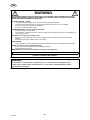
WARNING
READ AND UNDERSTAND THE INSTRUCTION MANUAL BEFORE INSTALLING OR OPERATING.
ARC WELDING AND CUTTING CAN BE INJURIOUS TO YOURSELF AND OTHERS. TAKE PRECAU-
TIONS WHEN WELDING. ASK FOR YOUR EMPLOYER’S SAFETY PRACTICES WHICH SHOULD BE
BASED ON MANUFACTURERS’ HAZARD DATA.
ELECTRIC SHOCK -- Can kill
S Install and earth the welding unit in accordance with applicable standards.
S Do not touch live electrical parts or electrodes with bare skin, wet gloves or wet clothing.
S Insulate yourself from earth and the workpiece.
S Ensure your working stance is safe.
FUMES AND GASES -- Can be dangerous to health
S Keep your head out of the fumes.
S Use ventilation, extraction at the arc, or both, to take fumes and gases away from your breathing zone
and the general area.
ARC RAYS -- Can injure eyes and burn skin.
S Protect y our eyes and body. Use the correct welding screen and filter lens and wear protective
clothing.
S Protect bystanders with suitable screens or curtains.
FIRE HAZARD
S Sparks (spatter) can cause fire. Make sure therefore that there are no inflammable materials nearby.
NOISE -- Excessive noise can damage hearing
S Protect y our ears. Use earmuffs or other hearing protection.
S Warn bystanders of the risk.
MALFUNCTION -- Call for expert assistance in the event of malfunction.
PROTECT YOURSELF AND OTHERS!
WARNING
This product is intended for industrial use. In a domestic environment this
product may cause r adio interference. It is the user’s responsibility to take
adequate precautions.
GB

-- 9 --
fza1d2ea
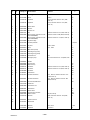
3 COMPONENT DESCRIPTION (LAF 630/800/1250/1600)
Unless otherwise stated, the components listed below are those as used in the
LAF 630, LAF 800, LAF 1250 and LAF 1600.
AP1 Circuit board
AP2 Circuit board, EMC filter (only for LAF 800/1250/1600)
C1 Capacitor, 1.0 ìF
C4 Capacitor
FU1 F use, 16 A slow--blow
FU2 Automatic fuse, 20 A
FU3 Fuse, 315 mA (only for LAF 800)
HL1 Indicating lamp (white), for Power On indication.
HL2 Indicating lamp (yellow), for indication of excess temperature.
KM1 Main contactor.
KM2 Auxiliary contactor (see page 27)
L1 Inductor
M1 Fan
QF Main On/Off switch.
QS Emergency stop pushbutton
(from serial no. 310 the emergency stop has been removed)
R1, R2 Resistor, 50W, 80 Ù
R3 Resistor (only for LAF 630/800)
R4 Resistor, inductor (only for LAF 630)
Resistor 680R (only for LAF 800/1250/1600 from serial no. 310)
RS1 Shunt (see page 28)
ST1 Thermal cutout (see page 28)
ST2 Thermal cutout (only for LAF 630), (see page 28)
TM1 Main transformer.
TC1 Control power supply transformer, 42V, 900 VA
TC2 Transformer for synchronising pulses (only LAF 1250/1600)
V1 Thyristor 1100A/300V (only for LAF 630/800/1250)
1500A/500V (only for LAF 1600).
V2 Diode.
V3 Diode bridge (basic current bridge) (only for LAF 630/800)
V4 Diode (only for LAF 800/1250/1600)
Diode bridge (basic voltage bridge) (only for LAF 630)
XS4 Burndy contact, 12--pole.
XS3 Pole terminal for voltage measurement.
XT2 Terminal block.
Z1--Z3 Suppressor
GB

claf0e2a
-- 1 0 --
fza1d2ea
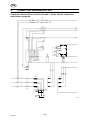
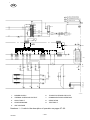
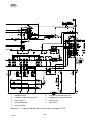
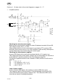
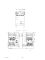
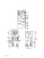
4 CONNECTION DIAGRAM (LAF 630)
Connection block XT2 is con n ected for 400 V / 50 Hz, see the con n ectio n
instruction o n pag e 40.
GB

-- 1 1 --
fza1d2ea
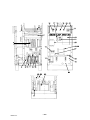
1. POWER SUPPLY
2. THERMAL OVERLOAD CUTOUT
3. SHUNT INPUT
4. SYNCHRONISING
5. ARC VOLTAGE
6. THYRISTOR FIRING CIRCUITS
7. COMMUNICATIONS INTERFACE
8. START/STOP
9. T EST INPUT
Numbers 1 -- 9 refer to the description of operation on pages 27--32.
GB
claf0e2b

-- 1 2 --
fza1d2ea
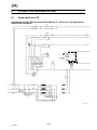
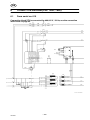
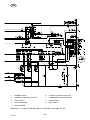
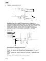
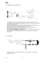
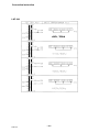
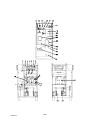
5 CONNECTION DIAGRAM (LAF 800)
5.1 From serial no. 615
Connection block XT2 is connected for 400/415 V / 50 Hz, see the connection
instruction o n pag e 41.
GB
fza1e3--800a

-- 1 3 --
fza1d2ea
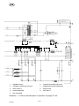
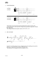
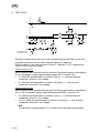
1. POWER SUPPLY
2. THERMAL OVERLOAD CUTOUT
3. SHUNT INPUT
4. SYNCHRONISING
5. ARC VOLTAGE
6. THYRISTOR FIRING CIRCUITS
7. COMMUNICATIONS INTERFACE
8. START/STOP
9. T EST INPUT
Numbers 1 -- 9 refer to the description of operation on pages 27--32.
GB
fza1e3--800b

-- 1 4 --
fza1d2ea
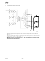
5.2 From serial no. 310
Connection block XT2 is connected for 400/415 V / 50 Hz, see the connection
instruction o n pag e 41.
GB

-- 1 5 --
fza1d2ea
1. POWER SUPPLY
2. THERMAL OVERLOAD CUTOUT
3. SHUNT INPUT
4. SYNCHRONISING
5. ARC VOLTAGE
6. THYRISTOR FIRING CIRCUITS
7. COMMUNICATIONS INTERFACE
8. START/STOP
9. T EST INPUT
Numbers 1 -- 9 refer to the description of operation on pages 27--32.
GB

-- 1 6 --
fza1d2ea
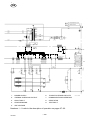
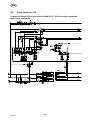
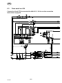
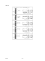
6 CONNECTION DIAGRAM (LAF 1250/ 1600)
6.1 From serial no. 615
Connection block XT2 is connected for 400/415 V / 50 Hz, see the connection
instruction o n pag e 42.
GB
fza1e4--12501600a

-- 1 7 --
fza1d2ea
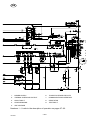
1. POWER SUPPLY
2. THERMAL OVERLOAD CUTOUT
3. SHUNT INPUT
4. SYNCHRONISING
5. ARC VOLTAGE
6. THYRISTOR FIRING CIRCUITS
7. COMMUNICATIONS INTERFACE
8. START/STOP
9. T EST INPUT
Numbers 1 -- 9 refer to the description of operation on pages 27--32.
GB
fza1e4--12501600b

-- 1 8 --
fza1d2ea
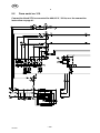
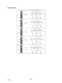
6.2 From serial no. 310
Connection block XT2 is connected for 400/415 V / 50 Hz, see the connection
instruction o n pag e 42.
GB

-- 1 9 --
fza1d2ea
1. POWER SUPPLY
2. THERMAL OVERLOAD CUTOUT
3. SHUNT INPUT
4. SYNCHRONISING
5. ARC VOLTAGE
6. THYRISTOR FIRING CIRCUITS
7. COMMUNICATIONS INTERFACE
8. START/STOP
9. T EST INPUT
Numbers 1 -- 9 refer to the description of operation on pages 27--32.
GB

-- 2 0 --
fza1d2ea
6.3 From serial no. 624
Connection block XT2 is connected for 400/415 V / 50 Hz, see the connection
instruction o n pag e 43.
GB
Page is loading ...
Page is loading ...
Page is loading ...
Page is loading ...
Page is loading ...
Page is loading ...
Page is loading ...
Page is loading ...
Page is loading ...
Page is loading ...
Page is loading ...
Page is loading ...
Page is loading ...
Page is loading ...
Page is loading ...
Page is loading ...
Page is loading ...
Page is loading ...
Page is loading ...
Page is loading ...
Page is loading ...
Page is loading ...
Page is loading ...
Page is loading ...
Page is loading ...
Page is loading ...
Page is loading ...
Page is loading ...
Page is loading ...
Page is loading ...
Page is loading ...
Page is loading ...
Page is loading ...
Page is loading ...
-
 1
1
-
 2
2
-
 3
3
-
 4
4
-
 5
5
-
 6
6
-
 7
7
-
 8
8
-
 9
9
-
 10
10
-
 11
11
-
 12
12
-
 13
13
-
 14
14
-
 15
15
-
 16
16
-
 17
17
-
 18
18
-
 19
19
-
 20
20
-
 21
21
-
 22
22
-
 23
23
-
 24
24
-
 25
25
-
 26
26
-
 27
27
-
 28
28
-
 29
29
-
 30
30
-
 31
31
-
 32
32
-
 33
33
-
 34
34
-
 35
35
-
 36
36
-
 37
37
-
 38
38
-
 39
39
-
 40
40
-
 41
41
-
 42
42
-
 43
43
-
 44
44
-
 45
45
-
 46
46
-
 47
47
-
 48
48
-
 49
49
-
 50
50
-
 51
51
-
 52
52
-
 53
53
-
 54
54


ESAB LAF 630/ LAF 800 / LAF 1250/ LAF 1600 User manual
- Category
- Welding System
- Type
- User manual
Ask a question and I''ll find the answer in the document
Finding information in a document is now easier with AI
Related papers
-
ESAB TAF 800 / TAF 1250 User manual
-
ESAB LAF 631 User manual
-
ESAB LAF 1250 User manual
-
ESAB LAF 1600 User manual
-
-
-
-
-
ESAB LAF 1600M User manual
-
ESAB LAF 1250M User manual
Other documents
-
Orchard Audio sk-module Operating instructions
-
SmartWitness AP1 EMEA Installation guide
-
 Tronix Explorer XT3 User manual
-
ABB DCS 600 MultiDrive Series User manual
-
Janam XT3 User guide
-
Aiphone LAF-10S User manual
-
-
-
Sensata AP1 Video Telematics User guide
-
 Master Bilt TAC-48HDSA User manual

