CYP PUV-44XPL-4K22-KIT User manual
- Category
- Video switches
- Type
- User manual
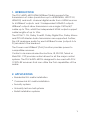
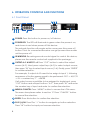
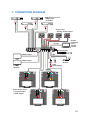
CYP PUV-44XPL-4K22-KIT is a 4x4 HDMI matrix with 2 independent HDMI outputs and audio de-embedding, supporting resolutions up to 4K@60Hz, HDCP 2.2, and PoH (Power over HDBaseT). It allows transmission of video and audio signals up to 70 meters over a single CAT5e/6/7 cable to compatible receivers. Features include automatic EDID management, bi-directional IR support, and control via RS-232, remote control, on-panel control, Telnet, and WebGUI. Suitable for residential and commercial AV installations, security systems, and university lecture halls.
CYP PUV-44XPL-4K22-KIT is a 4x4 HDMI matrix with 2 independent HDMI outputs and audio de-embedding, supporting resolutions up to 4K@60Hz, HDCP 2.2, and PoH (Power over HDBaseT). It allows transmission of video and audio signals up to 70 meters over a single CAT5e/6/7 cable to compatible receivers. Features include automatic EDID management, bi-directional IR support, and control via RS-232, remote control, on-panel control, Telnet, and WebGUI. Suitable for residential and commercial AV installations, security systems, and university lecture halls.


-
 1
1
-
 2
2
-
 3
3
-
 4
4
-
 5
5
-
 6
6
-
 7
7
-
 8
8
-
 9
9
-
 10
10
-
 11
11
-
 12
12
-
 13
13
-
 14
14
-
 15
15
-
 16
16
-
 17
17
-
 18
18
-
 19
19
-
 20
20
-
 21
21
-
 22
22
-
 23
23
-
 24
24
-
 25
25
-
 26
26
-
 27
27
-
 28
28
-
 29
29
-
 30
30
-
 31
31
-
 32
32
-
 33
33
-
 34
34
-
 35
35
-
 36
36
-
 37
37
-
 38
38
-
 39
39
-
 40
40


CYP PUV-44XPL-4K22-KIT User manual
- Category
- Video switches
- Type
- User manual
CYP PUV-44XPL-4K22-KIT is a 4x4 HDMI matrix with 2 independent HDMI outputs and audio de-embedding, supporting resolutions up to 4K@60Hz, HDCP 2.2, and PoH (Power over HDBaseT). It allows transmission of video and audio signals up to 70 meters over a single CAT5e/6/7 cable to compatible receivers. Features include automatic EDID management, bi-directional IR support, and control via RS-232, remote control, on-panel control, Telnet, and WebGUI. Suitable for residential and commercial AV installations, security systems, and university lecture halls.
Ask a question and I''ll find the answer in the document
Finding information in a document is now easier with AI
Related papers
Other documents
-
infobit H44H150 User manual
-
Black Box AC2000A Datasheet
-
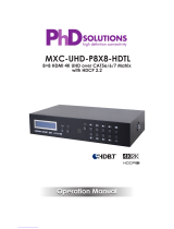 PhD Solutions MXC-UHD-P8X8-HDTL Operating instructions
-
VigilLink VLMX-862HT70 User manual
-
Comprehensive CHE-HDBTWP110K User manual
-
KanexPro MX-HDBT8X818G User manual
-
KanexPro HDMX44A-18G User manual
-
Key Digital KD-8x4CS Champion Setup Manual
-
 Cypress CMSI-8H8HS Operating instructions
-
 VivoLink VLHDMIEXTHDB2.0 User manual


