
Installation and
Reference Guide
HP J3178A
HP AdvanceStack Switch 208/224
Management Module
YUMAMOD.BK : 0_ymfcvr.fm5 Page 1 Thursday, February 20, 1997 12:54 PM

YUMAMOD.BK : 0_ymfcvr.fm5 Page 2 Thursday, February 20, 1997 12:54 PM

HP AdvanceStack Switch 208/224
Management Module
Installation and Reference Guide
YUMAMOD.BK : 0_ymfrnt.fm5 Page i Thursday, February 20, 1997 12:54 PM

Hewlett-Packard Company
8000 Foothills Boulevard, m/s 5551
Roseville, California 95747-5551
http://www.hp.com/go/network_city
© Copyright 1997 Hewlett-Packard Company
All Rights Reserved.
This document contains information which is protected by
copyright. Reproduction, adaptation, or translation without
prior permission is prohibited, except as allowed under the
copyright laws.
Publication Number
5966-5228
Edition 1
March 1997
Applicable Product
HP J3178A Switch 208/224 Management Module
Disclaimer
The information contained in this document is subject to
change without notice.
HEWLETT-PACKARD COMPANY MAKES NO WARRANTY
OF ANY KIND WITH REGARD TO
THIS MATERIAL, INCLUDING, BUT NOT LIMITED TO,
THE IMPLIED WARRANTIES OF MERCHANTABILITY
AND FITNESS FOR A PARTICULAR PURPOSE. Hewlett-
Packard shall not be liable for errors contained herein or for
incidental or consequential damages in connection with the
furnishing, performance, or use of this material.
Hewlett-Packard assumes no responsibility for the use or
reliability of its software on equipment that is not furnished
by Hewlett-Packard.
Warranty
A copy of the specific warranty terms applicable to your
Hewlett-Packard products and replacement parts can be
obtained from your HP Sales and Service Office or
authorized dealer.
YUMAMOD.BK : 0_ymfrnt.fm5 Page ii Thursday, February 20, 1997 12:54 PM

Perforate
✂
(over for more services)
HP Customer Support Services
How to get the latest software/agent firmware
You can download from the World Wide Web, HP FTP Library Service, CompuServe,
and HP BBS a compressed file (j3178xx.exe) containing the latest version of the HP
Switch 208/224 Management Module software and proprietary MIB. After you down-
load the file, extract the file by typing
filename
and pressing
[Enter].
For example, j317801 [Enter].
World Wide Web
http://www.hp.com/go/network_city
Select the “Support” section.
From this web site, you can also download information on the HP networking prod-
ucts. If you have a growing network, download the Designing HP AdvanceStack
Workgroup Networks Guide or call 1-800-752-0900 in the U.S. to receive a copy through
the mail.
HP FTP Library Service
1. FTP to Internet IP Address — ftp ftp.hp.com.
2. Log in as anonymous and press [Return] at the password prompt.
3. Enter bin to set the transfer type.
4. Enter cd /pub/networking/software.
5. Enter get
filename
to transfer the file to your computer, then quit.
CompuServe
1. Login to CompuServe.
2. Go to the “hp” service.
3. Select “HP Systems, Disks, Tapes, etc.”
4. Select “Networking Products” library.
5. Download
filename
and then quit.
HP BBS
Set your modem to no parity, eight bits, 1 stop bit, set speed up to 14400 bps, and with
your telecommunication program (e.g., Windows Terminal) dial (208) 344-1691 in the
U.S. to get the latest software for your HP networking product. For other countries,
see http://www.hp.com/cposupport/eschome.html.
Obtain the latest console code (j3178xx.exe) from:
HP FTP Library: ftp ftp-boi.external.hp.com
World Wide Web: http://www.hp.com/go/network_city
HP BBS: (208) 344-1691
(over)
YUMAMOD.BK : 0_ymperf.fm5 Page 3 Thursday, February 20, 1997 12:54 PM

Perforate
✂
HP FIRST Fax Retrieval Service
HP FIRST is an automated fax retrieval service that is available 24 hours a day, seven
days a week. HP FIRST provides information on the following topics:
■ Product information
■ Troubleshooting instructions
■ Technical reviews and articles
■ Configuration information
To access HP FIRST, dial one of the following phone numbers:
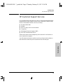
Additional HP Support Services
In addition to the above services, you can purchase various HP telephone support
services which provide you expert HP technical assistance:
■ Network Phone-In Support provides you support at an hourly rate. In the U.S.,
call 1-800-790-5544. In other countries, please contact your local HP Response
Center to see if this service is available in your country.
■ HP SupportPack Comprehensive Network Support provides complete prob-
lem resolution for medium to large interconnected local and wide area
networks. Contact your HP Authorized Reseller or the nearest HP Sales and
Support Office for more information.
HP offers other hardware support services. Please contact your reseller for more
information.
Location Phone Number
U.S. and Canada Only Dial 1 (800) 333-1917 with your fax machine or touch-tone phone
and press 1.
Outside the U.S. and Canada Dial 1 (208) 344-4809 from your fax machine and press 9.
To receive a list of currently available documents, enter document number 19941. The information
you requested will be sent to you by return fax. For other countries, see http://www.hp.com/
cposupport/eschome.html.
CompuServe: Go hpsys
Lib 7.
Download j3178xx.exe
Network Phone-In
Support (hourly):
1-800-790-5544
YUMAMOD.BK : 0_ymperf.fm5 Page 4 Thursday, February 20, 1997 12:54 PM

v
Contents
1 Installing the Management Module
Included Parts . . . . . . . . . . . . . . . . . . . . . . . . . . . . . . . . . . . . . . . . . . . . . . . . 1-2
Installation Steps . . . . . . . . . . . . . . . . . . . . . . . . . . . . . . . . . . . . . . . . . . . . . 1-2
Removing the Module . . . . . . . . . . . . . . . . . . . . . . . . . . . . . . . . . . . . . . . . . . 1-4
2 Management Module Description
Overview . . . . . . . . . . . . . . . . . . . . . . . . . . . . . . . . . . . . . . . . . . . . . . . . . . . . . 2-1
Module Features . . . . . . . . . . . . . . . . . . . . . . . . . . . . . . . . . . . . . . . . . . . . . . 2-3
3 The Switch Console
Overview . . . . . . . . . . . . . . . . . . . . . . . . . . . . . . . . . . . . . . . . . . . . . . . . . . . . . 3-1
Connecting a Console to the Switch . . . . . . . . . . . . . . . . . . . . . . . . . . . . 3-2
Modem Cable Pin-Out . . . . . . . . . . . . . . . . . . . . . . . . . . . . . . . . . . . . . . . . 3-5
Starting and Ending a Console Session . . . . . . . . . . . . . . . . . . . . . . . . . 3-6
Main Menu Features . . . . . . . . . . . . . . . . . . . . . . . . . . . . . . . . . . . . . . . . . . 3-8
Screen Structure and Navigation . . . . . . . . . . . . . . . . . . . . . . . . . . . . . . . 3-9
Using Password Security . . . . . . . . . . . . . . . . . . . . . . . . . . . . . . . . . . . . . . 3-11
Rebooting the Switch . . . . . . . . . . . . . . . . . . . . . . . . . . . . . . . . . . . . . . . . . 3-15
Advanced Commands . . . . . . . . . . . . . . . . . . . . . . . . . . . . . . . . . . . . . . . . . 3-17
4 Configuring the Switch From the Console
Overview . . . . . . . . . . . . . . . . . . . . . . . . . . . . . . . . . . . . . . . . . . . . . . . . . . . . . 4-1
Configurable Features . . . . . . . . . . . . . . . . . . . . . . . . . . . . . . . . . . . . . . . . . 4-3
System Configuration . . . . . . . . . . . . . . . . . . . . . . . . . . . . . . . . . . . . . . . . 4-4
Port Configuration . . . . . . . . . . . . . . . . . . . . . . . . . . . . . . . . . . . . . . . . . . 4-5
IPX Service . . . . . . . . . . . . . . . . . . . . . . . . . . . . . . . . . . . . . . . . . . . . . . . . . 4-6
Internet (IP) Service . . . . . . . . . . . . . . . . . . . . . . . . . . . . . . . . . . . . . . . . . 4-8
Using Bootp . . . . . . . . . . . . . . . . . . . . . . . . . . . . . . . . . . . . . . . . . . . . . . . . 4-9
YUMAMOD.BK : yumamod.TOC Page v Thursday, February 20, 1997 12:54 PM

vi
SNMP Communities
. . . . . . . . . . . . . . . . . . . . . . . . . . . . . . . . . . . . . . . . 4-12
Trap Receivers . . . . . . . . . . . . . . . . . . . . . . . . . . . . . . . . . . . . . . . . . . . . . 4-14
Serial Link Configuration . . . . . . . . . . . . . . . . . . . . . . . . . . . . . . . . . . . . 4-15
Console Configuration . . . . . . . . . . . . . . . . . . . . . . . . . . . . . . . . . . . . . . 4-16
Spanning Tree Configuration . . . . . . . . . . . . . . . . . . . . . . . . . . . . . . . . . 4-17
Network Monitoring Port . . . . . . . . . . . . . . . . . . . . . . . . . . . . . . . . . . . . 4-19
Saving Configurations . . . . . . . . . . . . . . . . . . . . . . . . . . . . . . . . . . . . . . . . 4-21
5 Monitoring Switch Operation From the Console
Overview . . . . . . . . . . . . . . . . . . . . . . . . . . . . . . . . . . . . . . . . . . . . . . . . . . . . . 5-1
Status and Counters Menu . . . . . . . . . . . . . . . . . . . . . . . . . . . . . . . . . . . . . 5-2
Switch Information . . . . . . . . . . . . . . . . . . . . . . . . . . . . . . . . . . . . . . . . . . 5-3
Port Status . . . . . . . . . . . . . . . . . . . . . . . . . . . . . . . . . . . . . . . . . . . . . . . . . 5-4
Port Counters . . . . . . . . . . . . . . . . . . . . . . . . . . . . . . . . . . . . . . . . . . . . . . . 5-5
Port Counters - Show Details . . . . . . . . . . . . . . . . . . . . . . . . . . . . . . . . . . 5-6
Address Table . . . . . . . . . . . . . . . . . . . . . . . . . . . . . . . . . . . . . . . . . . . . . . 5-7
Port Address Table . . . . . . . . . . . . . . . . . . . . . . . . . . . . . . . . . . . . . . . . . . 5-8
Spanning Tree (STP) Information . . . . . . . . . . . . . . . . . . . . . . . . . . . . . 5-10
Event Log . . . . . . . . . . . . . . . . . . . . . . . . . . . . . . . . . . . . . . . . . . . . . . . . . . . . 5-12
6 Using SNMP To Monitor and Manage the Switch
Overview . . . . . . . . . . . . . . . . . . . . . . . . . . . . . . . . . . . . . . . . . . . . . . . . . . . . . 6-1
SNMP Management Features . . . . . . . . . . . . . . . . . . . . . . . . . . . . . . . . . . 6-2
SNMP Configuration Process . . . . . . . . . . . . . . . . . . . . . . . . . . . . . . . . . . 6-3
Advanced Management: RMON and EASE Support . . . . . . . . . . . . . . 6-4
RMON . . . . . . . . . . . . . . . . . . . . . . . . . . . . . . . . . . . . . . . . . . . . . . . . . . . . . 6-4
EASE . . . . . . . . . . . . . . . . . . . . . . . . . . . . . . . . . . . . . . . . . . . . . . . . . . . . . . 6-4
7 Troubleshooting
Checking the Module LEDs . . . . . . . . . . . . . . . . . . . . . . . . . . . . . . . . . . . . 7-2
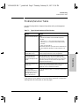
Problem/Solution Table . . . . . . . . . . . . . . . . . . . . . . . . . . . . . . . . . . . . . . . . 7-3
IP Configuration Errors . . . . . . . . . . . . . . . . . . . . . . . . . . . . . . . . . . . . . . . 7-4
Diagnostic Tests . . . . . . . . . . . . . . . . . . . . . . . . . . . . . . . . . . . . . . . . . . . . . . 7-4
YUMAMOD.BK : yumamod.TOC Page vi Thursday, February 20, 1997 12:54 PM

vii
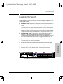
Testing the Switch and Management Module
. . . . . . . . . . . . . . . . . . . . 7-4
Testing the Switch’s Ports and the Links . . . . . . . . . . . . . . . . . . . . . . . . 7-5
Resetting the Switch . . . . . . . . . . . . . . . . . . . . . . . . . . . . . . . . . . . . . . . . . . 7-7
Clearing Passwords on the Switch Console . . . . . . . . . . . . . . . . . . . . . 7-8
HP Customer Support Services . . . . . . . . . . . . . . . . . . . . . . . . . . . . . . . . . 7-9
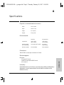
A Specifications
Regulatory Statements . . . . . . . . . . . . . . . . . . . . . . . . . . . . . . . . . . . . . . A-3
B Modem Configuration
C File Transfers
Overview . . . . . . . . . . . . . . . . . . . . . . . . . . . . . . . . . . . . . . . . . . . . . . . . . . . . C-1
Downloading an Operating System . . . . . . . . . . . . . . . . . . . . . . . . . . . . C-1
Using TFTP To Download the OS File . . . . . . . . . . . . . . . . . . . . . . . . . C-2
Using the SNMP-Based HP Download Manager . . . . . . . . . . . . . . . . . C-4
Using the Switch-to-Switch Download . . . . . . . . . . . . . . . . . . . . . . . . . C-4
Using the Zmodem to Download the OS File . . . . . . . . . . . . . . . . . . . C-5
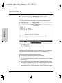
Troubleshooting TFTP Downloads . . . . . . . . . . . . . . . . . . . . . . . . . . . . C-6
Transferring Switch Configurations . . . . . . . . . . . . . . . . . . . . . . . . . . . C-8
D Spanning Tree Operation
Spanning Tree Protocol (STP) . . . . . . . . . . . . . . . . . . . . . . . . . . . . . . . . D-1
YUMAMOD.BK : yumamod.TOC Page vii Thursday, February 20, 1997 12:54 PM

viii
YUMAMOD.BK : yumamod.TOC Page viii Thursday, February 20, 1997 12:54 PM

1-1
Installing the Management Module
Installing the Management
Module
1
Installing the Management Module
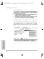
The HP J3178A AdvanceStack Switch 208/224 Management Module is installed
into the front of the HP AdvanceStack Switch 208T or 224T.
In this manual, this module will be called the Switch Management Module.
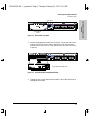
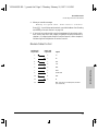
Figure 1-1. The Switch 208/224 Management Module
When installed, the Switch Management Module adds these features to your
switch:
■ Access to the switch console from which you can configure, monitor, and
troubleshoot the switch
■ Access to the switch from SNMP network management programs, such
as HP AdvanceStack Assistant, for controlling the switch using an
advanced, graphics-based interface
■ Configurable full-duplex port operation
■ Configurable support for the Spanning Tree Protocol for switched
networks
■ Configurable MAC Address Table aging
This chapter shows you how to install your Switch Management Module.
Switch Management Module
Base MAC Address
Active
YUMAMOD.BK : 1_yminst.fm5 Page 1 Thursday, February 20, 1997 12:54 PM

1-2
Installing the Management Module
Included Parts
Installing the Management
Module
Included Parts
Verify that these parts were included with the product:
• Switch 208/224 Management Module
• HP AdvanceStack Switch 208/224 Management Module
Installation and Reference Guide (5966-5228), this manual
• Console cable (5182-4794)
• HP AdvanceStack Assistant for Windows CD kit
• HP AdvanceStack Products CD kit
Installation Steps
Caution Anti-Static Precautions:
Static electricity can severely damage the sensitive electronic components on
the module. When installing the module in your switch, follow these proce-
dures to avoid damage from static electricity:
■ Handle the module by its edges and avoid touching the components and
the circuitry on the board.
■ Equalize any static charge difference between your body and the switch
by wearing a wrist static-protector strap and attaching it to the switch's
metal body, or by frequently touching the switch's metal body while you
are installing the module.
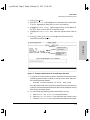
1. Before installing the Switch Management Module, unplug your switch
from the power source. This protects the module and switch from poten-
tial electrical damage.
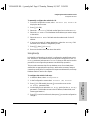
2. Unscrew the two captured screws holding the cover plate to the switch's
Management Slot and remove the cover, as shown in figure 1-2. Note that
the screws will release outward when unscrewed far enough. Do not
unscrew them completely from the cover plate.
YUMAMOD.BK : 1_yminst.fm5 Page 2 Thursday, February 20, 1997 12:54 PM

1-3
Installing the Management Module
Installation Steps
Installing the Management
Module
Figure 1-2. Remove the cover plate
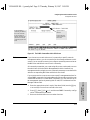
3. Insert the Management Module into the switch. Line up the sides of the
module with the rails on the sides of the switch’s slot, then push the
module into the slot until it is firmly seated in the connector in the back
of the slot.
Figure 1-3. Insert the Switch Management Module
4. Tighten the two screws that hold the module in place. Be careful not to
overtighten the screws.
Loosen these
screws
cover plate
Switch Management Module
YUMAMOD.BK : 1_yminst.fm5 Page 3 Thursday, February 20, 1997 12:54 PM

1-4
Installing the Management Module
Removing the Module
Installing the Management
Module
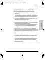
5. Turn on the power to the switch by plugging in the power cord. During
power-on, the following occurs:
If the module Fault LED stays on or flashes, refer to chapter 7, “Trouble-
shooting” in this guide.
You have now completed installation and verification of the module.
To configure IP/IPXcommunication for the Switch Management Module, see
chapter 4, “Configuring the Switch From the Console”.
Removing the Module
The module is removed from the switch by reversing the installation steps
described earlier in this document. When handling the module, be sure to
follow the anti-static precautions described on page 1-2.
To remove the module, follow these steps:
1. Remove power from the switch by unplugging the power cord.
2. Unscrew the two captured screws holding the module in the switch.
3. Pull the module out of the slot.
4. Replace the Management Slot cover plate.
Caution Replace the cover plate over the slot using the two screws that hold it in place.
Be careful not to overtighten the screws. When using the switch, the cover
plate must always be installed. This is required for safety and to ensure proper
switch cooling.
At Power On The switch begins its power-on self test followed by the module’s self
test. Ports are temporarily disabled until the Switch Management
Module configures the ports.
During Self Test All Switch and Module LEDs are on for approximately 5 seconds, then
just the switch Power and Fault LEDs and the Management Module
Self Test and Fault LEDs are on for the remainder of the self test. The
switch and module self tests require approximately 15 seconds total.
After Self Test The switch Fault LED and the module LEDs (Self Test and Fault) turn off.
YUMAMOD.BK : 1_yminst.fm5 Page 4 Thursday, February 20, 1997 12:54 PM

2-1
2
Management Module Description
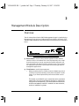
Overview
The HP AdvanceStack Switch 208/224 Management Module is installed in the
Management Slot in the front of either the HP Switch 208T or HP Switch 224T.
The Switch Management Module has the physical elements shown in the figure
below.
■ Reset Button - used to reboot the Management Module and the
switch in which it is installed. This clears any temporary error condi-
tions that may have occurred, executes the module and switch self
tests, and returns all network activity counters to zero. The counters
are displayed in the switch console interface and through network
management applications.
■ Clear Button - used for these purposes:
• When pressed by itself for at least one second, deletes any switch
console access passwords that you may have configured. Use this
feature if you have misplaced the password and need console
access.
This button is provided for your convenience, but its presence
means that if you are concerned with the security of the switch
configuration and operation, you should make sure the switch
with the management module is installed in a secure location,
such as a locked wiring closet.
YUMAMOD.BK : 2_ymdesc.fm5 Page 1 Thursday, February 20, 1997 12:54 PM

2-2
Management Module Description
Overview
Management Module
Description
• When pressed with the Reset button in a specific pattern, clears
any configuration changes you may have made through the
switch console and SNMP management, and restores the factory
default configuration to the switch and the module. See “Restor-
ing the Factory Default Configuration” in chapter 7, “Trouble-
shooting” for the specific method to restore the factory default
configuration.
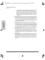
■ Self Test LED - When lit, indicates that the Management Module or
the switch in which the module is installed is undergoing its self test,
which occurs every time the switch is plugged into a power source,
or as a result of pressing the Reset button on the Management Module,
or from rebooting or resetting the switch from the switch console or
from network management.
■ Fault LED - When lit with the Self Test LED, indicates that the
Management Module is executing its self test. The self test normally
takes approximately 10 seconds. If the Self Test and Fault LEDs stay
on for longer than this, or if the Fault LED is flashing at any time, an
error has occurred on the module. See chapter 7, “Troubleshooting”
for more information on the LED and error recovery procedures.
■ Console RS-232 Port - This port is used to connect a console to the
switch, either directly using the serial cable supplied with the
Management Module, or through a modem connection. These connec-
tions are described in chapter 3, “The Switch Console”. The console
can be either a PC running a VT-100 terminal emulator, or a VT-100
terminal itself.
■ MAC Address - This is the unique hardware identity of the manage-
ment module. It is also used to identify the switch into which the
module is installed, and can be used in network connectivity tests
between the switch and other network devices. In an IPX network,
this address is also used as the Node Address part of the IPX network
address.
YUMAMOD.BK : 2_ymdesc.fm5 Page 2 Thursday, February 20, 1997 12:54 PM

2-3
Management Module Description
Module Features
Management Module
Description
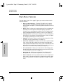
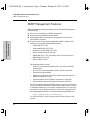
Module Features
When you install the Switch 208/224 Management Module in your Switch 208T
or 224T, you get these enhanced switch capabilities:
■ Full-duplex port operation. By default, the 10 Mbit/s and
100 Mbit/s ports on the Switch 208/224 operate in half-duplex mode.
With the Switch Management Module installed, these ports can be
configured to operate in full-duplex mode.
■ Address Aging. The Switch 208/224 automatically learns the MAC
address of the devices connected to its ports and stores those address-
es in an 8000-entry address table. When a device is moved, its new
location is automatically learned and kept in the table so proper
communication is maintained with the device. With the Management
Module installed, the additional benefit is that inactive addresses are
aged out of the table -- the table is kept up to date with the addresses
of active nodes only.
■ Spanning Tree Support. The Switch 208/224 uses the IEEE 802.1d
Spanning Tree Protocol (STP) to ensure that only one path at a time
is active between any two nodes in the network, thus preventing loops
that cause broadcast storms from occurring in the network topology.
By default, STP is disabled on the switch. You can use the switch console
to enable STP operation; see chapter 4, “Configuring the Switch From the
Console” for those configuration procedures. For more information on
how STP works, see appendix D, “Spanning Tree Operation”.
■ Switch Console. The Management Module has an RS-232 port to
which you can connect a console that can be used to configure,
monitor, and troubleshoot the switch and its ports. The console
interface can be used “out-of-band” from a PC or terminal directly
connected to the port or remotely through a modem connection, or
“in-band” through a Telnet session. For more information on the
switch console, see the section “Switch Console Features” in chapter
3, “The Switch Console”.
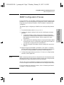
■ Network Management. The Management Module has firmware
agents on board that provide SNMP Network Management control of
the switch, support for RMON (four groups) and HP Embedded
Advanced Sampling Environment (EASE) agents to diagnose net-
work problems to help optimize network performance. For more
information the network management features provided by the Man-
agement Module and how to configure those features, see chapter 6,
“Using SNMP to Monitor and Manage the Switch”.
YUMAMOD.BK : 2_ymdesc.fm5 Page 3 Thursday, February 20, 1997 12:54 PM

YUMAMOD.BK : 2_ymdesc.fm5 Page 4 Thursday, February 20, 1997 12:54 PM

3-1
The Switch Console
3
The Switch Console
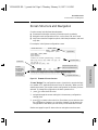
Overview
About the Console Interface. The console interface enables you to recon-
figure the switch and to monitor the switch status and performance. It consists
of a series of management screens accessed through a menu-driven screen
structure that begins at the Main Menu.
The switch console interface enables you to use a PC or a terminal to do the
following:
■ Modify the switch’s configuration, or provide configuration for Telnet or
network management access from an SNMP-based management program
such as Hewlett-Packard’s AdvanceStack Assistant (ASA)
■ Monitor the switch and port status and network activity counters
■ Control console security by configuring passwords
■ Use the switch’s event log and some advanced commands to help in
troubleshooting
■ Download new software
Note The Switch 208/224 and its Management Module are shipped with a factory
default configuration that enables operation as a multiport learning bridge
when installed in a network. All ports are enabled, Spanning Tree Protocol
support is disabled, and SNMP network management is enabled over IPX and
IP (by way of Bootp). For this operation, connecting a console device is
unnecessary. However, for some of the other uses listed above, you will need
to use the switch console.
This chapter describes the following features:
■ Connecting a console to the switch (page 3-2)
■ Starting and ending a console session (page 3-6)
■ The Main Menu Features (page 3-8)
■ Screen structure and navigation (page 3-9)
■ Using password security (page 3-11)
■ Rebooting the switch (page 3-15)
YUMAMOD.BK : 3_ymcnsl.fm5 Page 1 Thursday, February 20, 1997 12:54 PM

3-2
The Switch Console
Connecting a Console to the Switch
The Switch Console
Connecting a Console to the Switch
The Switch 208/224 Management Module offers two methods of access to the
console interface:
■ Out-of-band console access:
• Directly connected to the Console RS-232 port, using a serial cable
and a PC running a VT-100 terminal emulator or an actual VT-100
terminal
• Remotely connected to the Console RS-232 port, using modems and
a PC running a terminal emulator or an actual terminal
■ In-Band access using Telnet from a PC or UNIX station on the network,
and a VT-100 terminal emulator. This method requires that you first
configure an IP address and subnet mask by using either out-of-band
console access or Bootp. The Management Module allows one outbound
and one inbound Telnet session to be running simultaneously. It can also
simultaneously support one console session through the Console RS-232
port and one Telnet console session.
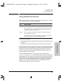
You can put security restrictions on console access by setting Manager-level
and Operator-level passwords. See “Using Password Security” later in this
chapter.
Default Serial Communication Settings
The default communication settings on the Switch Management Module are:
• 9600 baud
• 8 data bits
• 1 stop bit
• XON/XOFF
• For Windows Terminal program, also disable (uncheck) the “Use
Function, Arrow, and Ctrl
Keys for Windows” option.
Configure your PC or terminal to operate with these settings. If you want to
operate the terminal using a different configuration, make sure you change
with settings on both the terminal and on the switch. Change the switch
settings first, then change the terminal settings, and reestablish the console
session.
YUMAMOD.BK : 3_ymcnsl.fm5 Page 2 Thursday, February 20, 1997 12:54 PM
Page is loading ...
Page is loading ...
Page is loading ...
Page is loading ...
Page is loading ...
Page is loading ...
Page is loading ...
Page is loading ...
Page is loading ...
Page is loading ...
Page is loading ...
Page is loading ...
Page is loading ...
Page is loading ...
Page is loading ...
Page is loading ...
Page is loading ...
Page is loading ...
Page is loading ...
Page is loading ...
Page is loading ...
Page is loading ...
Page is loading ...
Page is loading ...
Page is loading ...
Page is loading ...
Page is loading ...
Page is loading ...
Page is loading ...
Page is loading ...
Page is loading ...
Page is loading ...
Page is loading ...
Page is loading ...
Page is loading ...
Page is loading ...
Page is loading ...
Page is loading ...
Page is loading ...
Page is loading ...
Page is loading ...
Page is loading ...
Page is loading ...
Page is loading ...
Page is loading ...
Page is loading ...
Page is loading ...
Page is loading ...
Page is loading ...
Page is loading ...
Page is loading ...
Page is loading ...
Page is loading ...
Page is loading ...
Page is loading ...
Page is loading ...
Page is loading ...
Page is loading ...
Page is loading ...
Page is loading ...
Page is loading ...
Page is loading ...
Page is loading ...
Page is loading ...
Page is loading ...
Page is loading ...
Page is loading ...
Page is loading ...
Page is loading ...
Page is loading ...
Page is loading ...
Page is loading ...
Page is loading ...
Page is loading ...
Page is loading ...
Page is loading ...
Page is loading ...
Page is loading ...
Page is loading ...
Page is loading ...
Page is loading ...
Page is loading ...
Page is loading ...
Page is loading ...
Page is loading ...
Page is loading ...
Page is loading ...
Page is loading ...
Page is loading ...
Page is loading ...
Page is loading ...
Page is loading ...
-
 1
1
-
 2
2
-
 3
3
-
 4
4
-
 5
5
-
 6
6
-
 7
7
-
 8
8
-
 9
9
-
 10
10
-
 11
11
-
 12
12
-
 13
13
-
 14
14
-
 15
15
-
 16
16
-
 17
17
-
 18
18
-
 19
19
-
 20
20
-
 21
21
-
 22
22
-
 23
23
-
 24
24
-
 25
25
-
 26
26
-
 27
27
-
 28
28
-
 29
29
-
 30
30
-
 31
31
-
 32
32
-
 33
33
-
 34
34
-
 35
35
-
 36
36
-
 37
37
-
 38
38
-
 39
39
-
 40
40
-
 41
41
-
 42
42
-
 43
43
-
 44
44
-
 45
45
-
 46
46
-
 47
47
-
 48
48
-
 49
49
-
 50
50
-
 51
51
-
 52
52
-
 53
53
-
 54
54
-
 55
55
-
 56
56
-
 57
57
-
 58
58
-
 59
59
-
 60
60
-
 61
61
-
 62
62
-
 63
63
-
 64
64
-
 65
65
-
 66
66
-
 67
67
-
 68
68
-
 69
69
-
 70
70
-
 71
71
-
 72
72
-
 73
73
-
 74
74
-
 75
75
-
 76
76
-
 77
77
-
 78
78
-
 79
79
-
 80
80
-
 81
81
-
 82
82
-
 83
83
-
 84
84
-
 85
85
-
 86
86
-
 87
87
-
 88
88
-
 89
89
-
 90
90
-
 91
91
-
 92
92
-
 93
93
-
 94
94
-
 95
95
-
 96
96
-
 97
97
-
 98
98
-
 99
99
-
 100
100
-
 101
101
-
 102
102
-
 103
103
-
 104
104
-
 105
105
-
 106
106
-
 107
107
-
 108
108
-
 109
109
-
 110
110
-
 111
111
-
 112
112


Ask a question and I''ll find the answer in the document
Finding information in a document is now easier with AI
Related papers
Other documents
-
 Hood J3250M User manual
-
 Asante Technologies 9000 User manual
-
Bay Networks BayStack 350 10 Series Datasheet
-
3com CS/2500 User manual
-
3com 4000 User manual
-
Agilent Technologies 4986B LanProbe User manual
-
3com SuperStack 3 Switch 4400 FX Getting Started Manual
-
HP (Hewlett-Packard) Laptop 2500 User manual
-
 Olicom CrossFire 8600 User manual
-
Intel 520T User manual


