Star Micronics TUP900 User manual

Category
Print & Scan
Type
User manual

This manual is also suitable for

1
Star Micronics America, Inc., 1150 King Georges Post Rd, Edison, NJ 088371
Date: 12/3/2007
TUP900
Revision 1.2
2
Star Micronics America, Inc., 1150 King Georges Post Rd, Edison, NJ 088372
Date: 12/3/2007
Getting Started
o Cable Connections - 4
o Loading Paper – 5
o Paper Feed Sensor Adjustment - 7
Driver Installation
o Driver Setup - 9
Troubleshooting
o Troubleshooting Printing Problems - 16
o Control Panel - 17
o Error Conditions - 19
o Dip Switches - 21
o Self-Test - 23
Specifications
o Basic Specifications – 27
Maintenance
o How to clean the sensor – 29
Status Monitor Setup
o Status Setup – 33
3
Star Micronics America, Inc., 1150 King Georges Post Rd, Edison, NJ 088373
Date: 12/3/2007
Getting Started
Assembly – Installing the Interface
Place the interface sub-assembly into the
interface slot as shown. Take care to be sure the
interface cartridge is seated properly into its
connector.
Using a #2 Phillips screwdriver, install the
mounting screws included with the printer.
Interface Type…
Parallel
Serial
USB
Ethernet
Printer Components:
Cable Connections:
Industry Standard Power Connector:
The TUP900’s power supply input is a female
Hoshiden (TCS7960-532010) connector. This
connector is common to the PS60L power
supply from Star, which is the recommend
power supply for the TUP900.
Connecting the Power Adapter:
4
Star Micronics America, Inc., 1150 King Georges Post Rd, Edison, NJ 088371
Date: 12/3/2007
Assembly Paper Roll Setup
It is necessary to adjust the paper roll holder for the width of the paper you use. If the setting position is incorrect, the
paper roll will be supplied improperly to the mechanism which in turn causes paper transport problems. Thus, it is should
be properly adjusted.
The following table shows the paper roll
holder and paper core inner diameter range.
Paper roll Holder
Types
Paper Core
Diameter Ranges
Paper roll Holder (1) 25.4 mm ± 1
Paper roll Holder (2) 50.8 mm ± 1
Paper roll Holder (3) 76.2 mm ± 1
Note 1) The unit is assembled for 1 inch paper
cores when shipped from the factory. Also, it is set
for a paper width of 111.5 ±0.5 (take-up width of
112 +0.5/-1) when the printer is shipped from the
factory.
Roll Holder Size Paper Thickness
1” or 25.4 mm 65 to 100 µm
2” or 50.8 mm 100 to 150 µm
3” or 76.2 mm 100 to 150 µm
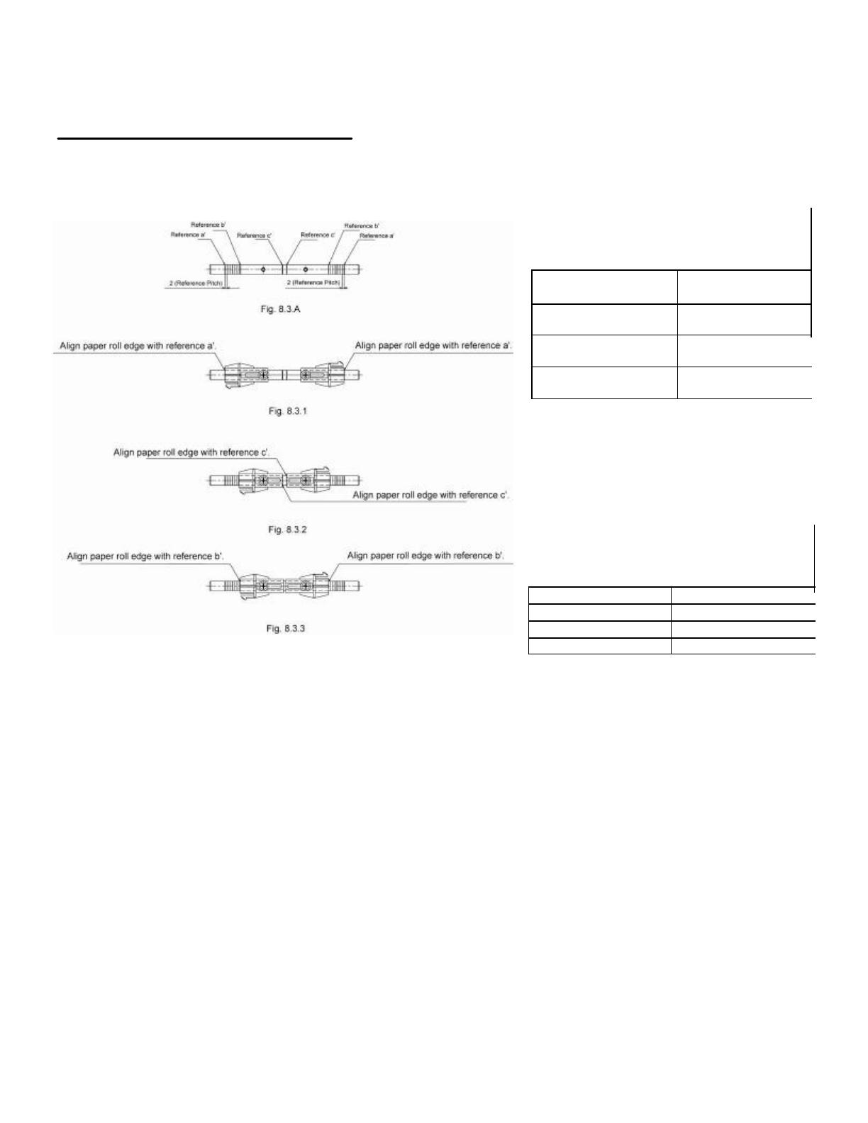
8.3 A is a reference for the paper roll holder unit paper roll shaft position. Adjust or mount the paper roll holder unit for
the core diameter and width of the paper you intend to use.
8-3-1 Handling 111.5 mm Paper Width
See Fig. 8.3.1 for the paper roll holder setting position to handle paper widths of 111.5 ±0.5 mm.
Position the edge of the paper roll holder onto the central position of the references a and a'.
See the figure to assembly at the correct position.
Note 1) The paper roll holder is assembled to that position when shipped from the factory.
8-3-2 Handling 82 mm Paper Width
See Fig. 8.3.2 for the paper roll holder setting position to handle paper widths of 82 ±0.5 mm.
Position the edge of the paper roll holder onto the central position of the references c and c'.
See the figure to assembly at the correct position.
Note 1) In this case, be careful because the edge of the paper roll holder positioned on the reference is the opposite.
8-3-3 Handling 79.5 mm Paper Width
See Fig. 8.3.3 for the paper roll holder setting position to handle paper widths of 79.5 ±0.5 mm.
Position the edge of the paper roll holder onto the central position of the references b and b'.
See the figure to assembly at the correct position.
Loading Paper:
5
Star Micronics America, Inc., 1150 King Georges Post Rd, Edison, NJ 088371
Date: 12/3/2007
Assembly Paper Roll Setup Continued
Once the paper roll holder is properly
configured for the roll to be used, simply insert
the roll holder into the paper core as show.
Be sure that the cut end of the paper roll is
properly cut to ensure proper paper loading.
To aid in the installation of the paper roll, the TUP900’s mechanism is hinged to the base of the
printer allowing the unit to fold open for easier access to the paper inlet path (see below)
Lift handle and pull unit forward.
In this position, it will be much easier to access
the paper inlet for loading of paper.
Position the paper roll as shown.
Slide the cut end of the paper roll into the paper
inlet being careful to feed the paper underneath
the damper rollers.
NOTE: The semi-auto paper loading of the TUP900 can sometimes cause the printer to enter
an error condition if paper is not allowed to feed smoothly into the paper inlet path. In the event
of an error,reset the printer by turning the power switch OFF and then ON again.
6
Star Micronics America, Inc., 1150 King Georges Post Rd, Edison, NJ 088371
Date: 12/3/2007
TUP900 Paper Feed Sensor Adjustment – See photos below
This is a multi-step process:
1. Ensure that the paper is loaded on the spindle and that the two black plastic
sleeves are positioned on either side of the paper roll in order to keep the roll
centered on the spindle and from sliding left or right.
2. Power on the printer. If the paper does not automatically feed through the
presenter on power up then you will see a solid red light on LED 2 that will start
flashing after a second or two following power up. At this point the paper width
sensor needs an adjustment.
3. Power off the printer.
4. Remove the printer from the kiosk and turn it upside down to locate the Paper
Feed Sensor assembly. Make sure the Presenter is closed.
Cogged Wheel
Black Raised Positioner
Paper Feed Senso
r
5. Turn the printer over and position the end of the paper under the rear white feed
rollers and slide the paper into the paper feed area.
White Feed
Rollers
Paper Feed Sensor Adjustment:
6. Power on the printer. You will see 2 lights, a solid green power LED 1 and a solid
Red error light on LED 2 that will start flashing after a second or two following
power up. If the printer needs a fine adjustment of the Paper Feed Sensor, turn the
printer over in order to access the sensor assembly.
7. Slowly slide the black raised positioner on the paper feed assembly until the red
error LED2 stops flashing and the paper begins to feeds *Warning: Over
adjustment will cause the paper to snag on the sensor.
8. At that point the paper width sensor is set properly to detect the new paper and the
printer is ready to be installed in the kiosk.
7
Star Micronics America, Inc., 1150 King Georges Post Rd, Edison, NJ 088371
Date: 12/3/2007
8
Star Micronics America, Inc., 1150 King Georges Post Rd, Edison, NJ 088374
Date: 12/3/2007
Driver Installation
9
Star Micronics America, Inc., 1150 King Georges Post Rd, Edison, NJ 088375
Date: 12/3/2007
DRIVERINSTALLATION:
Step1
Todownloaddriversfromourwebsitegotothebelowlink:
http://www.starmicronics.com/printers/printers_pages/support/drvr_frames/drvr_framset.html
YouwillneedtheRasterdriver.Whenyouclickonthelinktoopenthedriver,youwillseethePrinter
Driverinstaller(shownbelow):
Step2Parallel/SerialInstallation
Inthedrivermenu,chooseyourTUP900printermodel(TUP942orTUP992)
ForPort,chooseLPT1forParallelthenclickonthe1
st
optionAutomatedprinterinstall.
Step3
SayNOtotheLanguageMonitor
10
Star Micronics America, Inc., 1150 King Georges Post Rd, Edison, NJ 088376
Date: 12/3/2007
Step4
Whenyourprinterhasbeensuccessfullyinstalled,itwillcreateaprintericoninPrintersand
Faxes.Ifyouwouldliketoprintatestpage,sayyeswhenprompted.Yourprinterisnow
installedandreadytoprint.
______________________________________________________________________________
USBInstallation:
*Note:MakesuretheprinteristurnedofftheUSBcablecanbepluggedintothecomputer
andtheprinter.
Step1‐
ThePrinterDriverinstallerwillcomeup.
Step2
ForUSB,printersneedtobeinstalledmanuallyclickonthe3
rd
optionExtractFilesfor
installationviaWindowsAddprinterWizard
11
Step3
Ifyouintendtousethestatusmonitorfunctiontogetstatusfromtheprinter(recomm ended
forparallelandUSB)PleasechoosethedriveraccordinglyandsayYEStothequestionreStatus
Monitorinstallation.
Ifyouintendtousetheprinterwithoutstatusmonitor(onlyrecommendedforserialprinters)
pleasechoosethedriverandsayNOtothequestionreStatusMonitorinstallation.
Step4
ItwillextractaStarfoldertothedesktopclickOKtocloseandclickExitfromRasterdriver.
Step5
TurntheprinterON andtheFoundNewHardwareWizardwillcomeup.
Step6
ChoosethelastoptionNo,notthistimeandclickNext
Star Micronics America, Inc., 1150 King Georges Post Rd, Edison, NJ 088377
Date: 12/3/2007
12
Star Micronics America, Inc., 1150 King Georges Post Rd, Edison, NJ 088378
Date: 12/3/2007
Step7
ClickonthelastoptionInstallfromalistorspecificlocation(Advanced)andclickNext
Step8
Next,choosethelastoptionDon’tsearch.IwillchoosethedrivertoinstallandclickNext
13
Star Micronics America, Inc., 1150 King Georges Post Rd, Edison, NJ 088379
Date: 12/3/2007
Step9
ClickonHaveDisk..
Step10
ClickonBrowse
Step11
AtthetopinLookin,clickonDesktop
OpentheStarfolder
OpenStarRas
ClickonOEMPRINT.INFandclicktheOpenbuttonthenclickOK
14
Star Micronics America, Inc., 1150 King Georges Post Rd, Edison, NJ 0883710
Date: 12/3/2007
Step12
ChoosetheTUP900withoutStatusMonitorandclickNext
ThenclickNexttofinishthedriverinstallation.
YouwillclickFinishtoclosetheWizard
Step13
OpenPrintersandFaxesandtheTUP900drivershouldbelisted.
Youhavesuccessfully installedtheTUP900printer.
15
Star Micronics America, Inc., 1150 King Georges Post Rd, Edison, NJ 0883711
Date: 12/3/2007
Troubleshooting
16
Star Micronics America, Inc., 1150 King Georges Post Rd, Edison, NJ 0883712
Date: 12/3/2007
TROUBLESHOOTING:
BelowisalistofcommonissuesthatmayoccurwiththeTUP900and
resolutionsforthoseissues:
Issue:Custo
merdoesnotusepa
peradjustmenttofitthepapersizeoftheroll,causing
the
papertoshiftaround.
Resol
uti
on:Th
eTUP900hasapaperguidethatcanbeadjustedtousepaperthatis80mm
112mminwidth.Thepa
perguideisblackandplasticandislocatedbehindthepresenterand
canbeadjustedtofitthepaperwidth.
‐‐‐‐‐‐‐‐‐‐‐‐‐‐‐‐‐‐‐‐‐‐‐‐‐‐‐‐‐‐‐‐‐‐‐‐‐‐‐‐‐‐‐‐‐‐‐‐‐‐‐‐‐‐‐‐‐‐‐‐‐‐‐‐‐‐‐‐‐‐‐‐‐‐‐‐‐‐‐‐‐‐‐‐‐‐‐‐‐‐‐‐‐‐‐‐‐‐‐‐‐‐‐‐‐‐‐‐‐‐‐‐‐‐‐‐‐‐‐‐‐‐‐‐‐‐‐‐
Issue:Paperjamsinthepresenteran
diterrorsoutanddoesn’tcompleteprinting.
Resolution:Openpresenterinthefrontandclearoutpaperjamtoresumepri
nting.
‐‐‐‐‐‐‐‐‐‐‐‐‐‐‐‐‐‐‐‐‐‐‐‐‐‐‐‐‐‐‐‐‐‐‐‐‐‐‐‐‐‐‐‐‐‐‐‐‐‐‐‐‐‐‐‐‐‐‐‐‐‐‐‐‐‐‐‐‐‐‐‐‐‐‐‐‐‐‐‐‐‐‐‐‐‐‐‐‐‐‐‐‐‐‐‐‐‐‐‐‐‐‐‐‐‐‐‐‐‐‐‐‐‐‐‐‐‐‐‐‐‐‐‐‐‐‐‐
Issue:Customerwouldliketheprintertoloopinthepresentertoavoidcustom
erspullingthe
receiptoutwhileitisstillprinting.
Resolution:UsetheTUP900configurationutilitytoenabletheLo
opingfeature.
Issue:Whenthereceiptisfinishedprinting,itfeedsext
rapaperanderrorsout.
‐‐‐‐‐‐‐‐‐‐‐‐‐‐‐‐‐‐‐‐‐‐‐‐‐‐‐‐‐‐‐‐‐‐‐‐‐‐‐‐‐‐‐‐‐‐‐‐‐‐‐‐‐‐‐‐‐‐‐‐‐‐‐‐‐‐‐‐‐‐‐‐‐‐‐‐‐‐‐‐‐‐‐‐‐‐‐‐‐‐‐‐‐‐‐‐‐‐‐‐‐‐‐‐‐‐‐‐‐‐‐‐‐‐‐‐‐‐‐‐‐‐‐‐‐‐‐‐
Issue:Printjobsareremaininginprintqu
eueanddonotprint.
Resolution:Cleanthesensoronthepre
senter.
Issue:Whenthereceiptisfinishedprinting,itfeedsext
rapaperanderrorsout.
Resolution:Doaselftesttocheckifthe blackmarksens
orisValidorInvalid.
Ifblackmarkpaperisbeingusedmakesuretheblackmarksensor
isValid.
IfregularthermalpaperisbeingusedmakesuretheblackmarksensorisInvalid.
Toenable/disabletheblackmarksensor,
usetheTUP900configurationutility.Thisutilitycan
belocatedin
thedriverssectionoftheStarMicronicsAmerica,Inc.website.
Power LED Error LED
RedGreen
SW2 SW1
CHAPTER 6 OPERATION SPECIFICATIONS
6-1 Operation Panel Specifications
--------------------------------------------------------------------------------------------------------------- 1 When Power is ON
Hex Dump Mode
-------------------------------------------------------------------------- 2 When Power is ON (Sensor Adjustment Mode)
----------------------------------------------------------------------------------------------------------------------- 3 When Online
Printer Reset (Hold for 2 seconds)
--------------------------------------------------------------------------------------------------------------- 4 When errors occur
Paper Feed
Paper discharged
Error cancellation
Self-test
*
1
The switches and LEDs are on the board.
The drawing of the operation panel is for refer-
ence and may differ from the actual panel.
No Switch Input Sensor Adjustment Mode for PE/Black Mark
Adjustment mode for Paper Near End Sensor
Printer Reset (Hold for 2 seconds)
Control Panel Specifications:
17
Star Micronics America, Inc., 1150 King Georges Post Rd, Edison, NJ 088371
Date: 12/3/2007
1 When Power is ON
SW Input Operation
SW1 Self-test Print
SW2 Hex Dump Mode
2 When in Sensor Adjustment Mode and Power is ON (Sensor Adjustment Mode is selected using by
setting the DIPSW1-4 on the main board to OFF.)
SW Input Operation
No SW Input Sensor Adjustment Mode for PE/Black Mark
3 When Online
SW Input Operation
SW1 Paper Feed (*1)
SW1 + SW2 (Hold for 2 sec.) Printer Software Reset
*1) Details for Paper Feed Specifications
Presenter Contact Status Black Mark Function Paper Feed Specifications
Non-contact Disabled Paper feed continues while SW1 is input
Enabled Performs TOF operation
Contact Disabled Paper Feed + Full Cut + Presenter Paper Discharge
Ignores SW input under the following conditions
• When LF motor is operation
• When paper is being supplied to the presenter
Enabled TOF + Full Cut + Presenter Paper Discharge
Ignores SW input under the following conditions
• When LF motor is operation
• When paper is being supplied to the presenter
4 When errors occur
SW Input Operation
SW1 Paper Discharge (*2)
Function executed only under the following conditions
• Cover is closed • No Paper
SW2 Error cancel operation (according to MSW1-E settings)
*2) Paper Discharge
This function cancels the paper wait state of the platen that exists when there is no paper detected
when printing by feeding paper. Paper can be easily removed without opening the cover, by using this
function. However, caution must be exercise in using this function when there is no paper being
waited for at the platen because over use can damage the print head.
Status
LED Specifications
Power LED Error LED
Normal State ON OFF
Auto-recovery Error Printing stops because of Blink 500msec OFF
detection of the high
temperature of the head
Recoverable Errors PE Error ON Blink 500msec
NE Error ON Blink 2000msec
Cover Open Error ON ON
Black Mark Error ON Blink 500msec
Non-recoverable Errors Auto-cutter Errors OFF Blink 125msec
Presenter Paper Jam Errors OFF Blink 250msec
FLASH Access Errors OFF Blink 500msec
EEPROM Access Errors OFF Blink 750msec
SRAM Access Errors OFF Blink 1000msec
Thermistor Errors OFF Blink 1500msec
Power Voltage Errors OFF Blink 2000msec
18
This error automatically cancels E errors by varying the status internally on the printer.
Error LED Cause How to Recover
Power Error
Printing Stops Because Blink OFF Head Thermistor Automatic Recovery
Detection of High 500msec Temperature when Head Thermistor
Temperature Head Detected (When Temperature Detected to
detected to be Drop (When detected to be
over 60°C) under 55°C)
Identify Error Conditions:
This error cancels errors while maintaining the printer’s status, by executing a determined error
recovery means.
Error LED Cause How to Recover
Power Error
NE Error ON Blink Not enough paper Replace the paper
2000msec
PE Error ON Blink Paper Out Detection 1. Open the cover and remove the paper in
500msec the presenter and printer.
2. Replace the paper.
3. Manually setting of the paper
Set the paper and close the cover.
Error cancel SW input
Auto-loading of the Paper
Close the cover.
Insert paper into the printer’s paper supply
inlet.
Auto-loading starts.
4. Cut paper.
5 Paper discharged to front of presenter
when presenter is connected.
Cover Open ON ON Cover Detected to 1. Remove paper in the presenter and in the
Error be open printer.
2. Manually setting of the paper
Set the paper and close the cover.
Error cancel SW input
Auto-loading of the Paper Close the cover.
Insert paper into the printer’s paper supply
inlet.
Auto-loading starts.
3. Cut paper.
4 Paper discharged to front of presenter
when presenter is connected.
Black Mark ON Blink White detected over Black mark paper size error
Error 500msec 400 mm long Replace the Black Mark paper
Adjust sensitivity in the sensor
adjustment mode
19
Star Micronics America, Inc., 1150 King Georges Post Rd, Edison, NJ 088371
Date: 12/3/2007
This error requires the printer to be reset after executing a determined error recovery means because
a fatal error has occurred.
The printer many need to be repaired if the same error occurs even after resetting the printer.
Error LED Cause How to Recover
Power Error
Auto-cutter Errors OFF Blink Cutter failure Check/repair the cutter
125msec
Presenter Paper Jam Errors OFF Blink Paper jam in Remove paper from
250msec Presenter the Presenter
FLASH Access Errors OFF Blink FLASH ROM Repair
500msec Access Errors
EEPROM Access Errors OFF Blink EEPROM Repair
750msec Access Errors
SRAM Access Errors OFF Blink SRAM Access Repair
1000msec Errors
Thermistor Errors OFF Blink Head Repair
1500msec Thermistor
Error Value
Detected
Power Voltage Errors OFF Blink Power Voltage Check/repair the power
2000msec Error Value supply
Detected
20
Star Micronics America, Inc., 1150 King Georges Post Rd, Edison, NJ 088371
Date: 12/3/2007
  • Page 1 1
  • Page 2 2
  • Page 3 3
  • Page 4 4
  • Page 5 5
  • Page 6 6
  • Page 7 7
  • Page 8 8
  • Page 9 9
  • Page 10 10
  • Page 11 11
  • Page 12 12
  • Page 13 13
  • Page 14 14
  • Page 15 15
  • Page 16 16
  • Page 17 17
  • Page 18 18
  • Page 19 19
  • Page 20 20
  • Page 21 21
  • Page 22 22
  • Page 23 23
  • Page 24 24
  • Page 25 25
  • Page 26 26
  • Page 27 27
  • Page 28 28
  • Page 29 29
  • Page 30 30
  • Page 31 31
  • Page 32 32
  • Page 33 33
  • Page 34 34
  • Page 35 35
  • Page 36 36
  • Page 37 37

Star Micronics TUP900 User manual

Category
Print & Scan
Type
User manual
This manual is also suitable for

Ask a question and I''ll find the answer in the document

Finding information in a document is now easier with AI