
PRODUCT DATA
68-0259-1
® U.S. Registered Trademark
Copyright © 2002 Honeywell • All Rights Reserved
TZ-4 TotalZone® Zone Control Panel
APPLICATION
The TZ-4 TotalZone Zone Control Panel controls single-stage,
multi-stage, conventional or heat pump heat/cool equipment.
It controls 2, 3 or 4 zones, and is expandable up to 32 zones
with optional TotalZone® Add-A-Zone™ Four Zone Control
Panel.
FEATURES
• Up to three stages heat and two stages cooling can be
controlled by thermostat, built-in timer, or based on
the percentage of zones calling.
• Controls single-stage, multi-stage, conventional, heat
pump or dual-fuel equipment.
• Controls up to four zones and can be expanded up to
32 zones with Add-A-Zone Control Panels.
• Uses Honeywell four-wire, single-stage, multi-stage, or
select heat pump thermostats.
• Zone-A-Lone central setback feature.
• Purge timer protects equipment between calls for heat
or cool with choice of panel or HVAC equipment
controlled fan.
• System and zone damper LEDs indicate system and
damper status.
• Individual zone fan control.
• Discharge Air Temperature Sensor for capacity control
with adjustable high and low limits.
• Thermal circuit breaker protects panel and transformer
from damage if miswired.
For Internet access:
www.honeywellzoning.com
For technical support, call 1-800-828-8367.
To download Zoning literature: http://hbctechlit.honeywell.com
Contents
Application......................................................................... 1
Features ............................................................................ 1
Specifications .................................................................... 2
Installation ......................................................................... 4
Startup and Checkout........................................................ 12
Operation........................................................................... 12
Troubleshooting................................................................. 17

TZ-4 TOTALZONE® ZONE CONTROL PANEL
68-0259-1 2
SPECIFICATIONS
Input Ratings:
Voltage: 20-30 Vac, 50/60 Hz.
Power: 13 VA, nominal.
Output Ratings:
1.5A run, 200,000 cycles (30 Vac). 3.5 inrush.
1.5A run, 100,000 cycles (30 Vac) 7.5A inrush.
Humidity Ratings:
5 to 90 percent RH, non-condensing.
Temperature Ratings:
Shipping: -20° to 120°F.
Operating: -40° to 150°F.
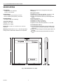
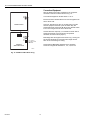
Dimensions: 10-3/4 in. H x 12-3/4 in. W x 1-7/8 in. D.
See Fig. 1.
Mounting: Mounts with four 1 in. no. 8 screws (provided)
through holes in cabinet back. Wall anchors are provided.
Wiring: 18-gauge wire for all equipment and system
connections.
Wiring Connections:
Thermostat: R, C, W1/E, W2, W3/AUX, Y1, Y2, G, L, O/B
Dampers: M6 (Closed); M4 (Open); M1 (Common).
Discharge Air Temperature Sensor (C7735A1000); DATS,
DATS.
Zone-A-Lone: OC, OC.
Outdoor Temperature: OT, OT.
Transformer 1: R (hot), C (common).
Transformer 2: T1 (hot), T2 (common).
Equipment: Rc-Rh, W1/E, W2, W3/AUX Y1, Y2, G, O/B.
Thermostats (See Table 1):
Most conventional four-wire (R,W,Y,G) thermostats can be
used to control conventional, heat pump, or multi-stage
equipment.
Manual or automatic changeover switching thermostats can
be used.
Multi-stage or select heat pump thermostats can also be
used.
Fig. 1. TZ-4 dimensions in in. (mm).
M20516
10-3/4
(273)
12-3/4
(273)
1-7/8
(47)

TZ-4 TOTALZONE® ZONE CONTROL PANEL
3 68-0259-1
a
Heat pump thermostat with single Y first-stage terminals. See Heat Pump Thermostats section and Fig. 6.
b
Multi-stage and heat pump thermostats are not required to control multi-stage and heat pump systems with TotalZone. They are
used only when second stage or emergency heat control from the zone thermostat is needed.
c
The Y594R1243 must be wired to the panel using the B terminal for changeover.
d
Cut thermostat second-stage variable heating anticipator wire (gray).
e
Cut thermostat first-stage fixed heating anticipator wire (bare) and second-stage variable heating anticipator wire (gray).
f
Cut thermostat second-stage cooling anticipator wire (lowest bare wire).
Recommended Dampers (See Table 2):
Ten ZD or ARD dampers maximum connected to each panel
and a maximum of five dampers per zone when using two
40 VA transformers.
Use SDCR and 40 VA transformer for additional dampers
required on one zone.
Dampers are connected to M1 Common, M4 Open, and M6
Closed (see Fig. 7-10 for hookups).
Accessories: For required accessories, see Table 3.
Table 1. Recommended Thermostats.
System Non-Programmable Programmable
Single Stage
T87F1859/Q539A1014
T87F4010/Q539A4026
T8501D1046
T8400C1016
T8400C1040
T8400C1099
T8601D2027
T8600D2069
T8600D2028
T8601D2019
T8602D2018
T8602D2000
T8000C1002
T8000C1010
T8001C1019
PC8900/W8900A/C
Heat Pump
b
Y594R1243
a,c,d
Y594G1252
a,e
T8411R1002
T8411R1028
T8611G2051
T8011R1006
T8011R1014
Multi-Stage
b
Y594D1347
f
T8524D1015
T8624D2004
T8624D2012
Motor Terminal Damper Action
Common/M1 Common
Open/M4 Power Open
Closed/M6 Power Close
Table 2. Recommended Dampers.
Honeywell Damper Type Round Rectangular
Power-open/power-closed (for
systems > 2000 cfm)
MARD D643 using
ML6161
Motor
Actuator
Spring-open/power-closed (for
systems </= 2000 cfm)
ARD ZD

TZ-4 TOTALZONE® ZONE CONTROL PANEL
68-0259-1 4
INSTALLATION
Mounting
CAUTION
Equipment Damage Hazard.
Do not mount TZ-4 inside HVAC equipment
Mount only on wall or on cold air return.
Identifying DIP Switches
This panel has two banks of DIP switches, DIP switch 4 (S4)
and DIP switch 5 (S5), see Fig 15. Each bank has eight
individual switches that are identified by two numbers; the first
number is the bank number (4 or 5) and the second number
identifies the individual switch. For example, DIP 5-1 is bank
5, switch 1.
1. Mount the thermostats in each zone of the living space
using the installation instructions provided with each
thermostat.
2. Mount the dampers in the ductwork using the installa-
tion instructions provided with each damper.
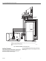
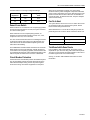
3. Mount the TZ-4 zone panel near the HVAC equipment;
(on a wall or on the cold-air return). See Fig. 2.
4. Level the TZ-4 for appearance only.
Wiring
CAUTION
Voltage Hazard.
Can cause electrical shock or equipment damage.
Disconnect power before continuing installation.
Wiring must comply with applicable codes, ordinances, and
regulations.
1. Connect thermostats as shown in Fig. 3-6.
2. Connect dampers as shown in Fig. 7-10.
3. Connect C7735A Discharge Air Temperature Sensor
(not supplied) to the DATS terminals. The wires are not
polarized. See Fig. 13.
4. Connect Add-A-Zone panels (if used) to the AZ1 and
AZ2 terminals.
5. Connect the HVAC equipment to the EQUIP terminals
on the panel. See Fig. 15-21.
6. Connect a 40 VA, 24 volt transformer to R (hot) and C
(common). This must be a dedicated transformer and
each TAZ-4 board also requires a transformer. See Fig.
12.
7. The auxiliary 40 VA 24-volt transformer can be con-
nected to T1 and T2 if additional power for dampers is
required. This second transformer is not required; how-
ever, total power consumption of panel and damper is
limited to 40VA without it.
Fig. 2. TZ-4 mounting location.
Table 3. Required Accessories (Not Supplied).
Accessory Description
Bypass Rating
(cfm)
40 VA
transformers
AT140D1046
(PMT-40)
—
Capacity
protector
C7735A1000 —
Outdoor
Temperature
Sensor
(Required for
dual-fuel
applications)
C7089B1000 —
Round static
pressure
regulator
damper
SPRD7
SPRD8
SPRD9
SPRD10
SPRD12
SPRD14
SPRD16
300
400
600
750
1200
1800
2400
Rectangular
static pressure
regulator
damper
SPRD12x8
SPRD12x10
SPRD12x12
SPRD20x8
SPRD20x10
SPRD20x12
1000
1200
1400
1600
2000
3000
M20517
WATER
HEATER
TZ-4
E
L
E
C
T
R
O
N
I
C
A
I
R
C
L
E
A
N
E
R
RET
U
R
N
AIR
TZ-4
OPTIONAL
LOCATION
FURNACE
OR BOILER
HIGH
EFFICIENCY
AIR CLEANER

TZ-4 TOTALZONE® ZONE CONTROL PANEL
5 68-0259-1
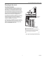
Wiring Diagrams (Fig. 3 and 4)
Conventional Thermostats
Conventional (RWYG) thermostats can be used to control
conventional, multi-stage, and heat pump equipment. If the
thermostat has a common terminal, it is wired to C on the
panel, see Fig. 3. A multi-stage thermostat is wired with the
second and third stage of heat to W2 and W3 on the panel
thermostat connections, and with the second stage of cooling
to Y2. Leave the zone O/B thermostat jumper on the TZ-4
disconnected. See Single and Multi-Stage Operation in the
Operation section for instructions on staging the TZ-4.
The PC8900 with the W8900A or W8900C can be used as a
zone thermostat. See Fig. 4 for hookup. This thermostat can
be used to control up to 2 heat and 2 cool stages of
conventional equipment. When used to control heat pump
equipment, the W8900A is recommended.
Connect a jumper on the W8900 from Rc to Rh as shown in
Fig. 4. Wire terminals R and C to a transformer. If the system
current draw is within specifications, the R and C on the
W8900 could alternately be connected to R and C on the
TZ-4. The PC8900/W8900 draws 5 VA.
Fig. 3. Typical single-stage thermostat wiring.
M20509B
G
C
R
Y
W
COMMON (C) TERMINAL IS USED ONLY BY THERMOSTATS
THAT REQUIRE A COMMON WIRE.
MULI-STAGE THERMOSTATS ARE WIRED SIMILARLY BUT WITH
Y2 AND W2 USED FOR SECOND STAGE COOL AND HEAT.
THIRD STAGE OF HEAT (W3) CAN BE WIRED TO W3/AUX.
LEAVE O/B JUMPER ON TZ-4 DISCONNECTED.
TZ-4 THERMOSTAT
CONNECTORS
TYPICAL SINGLE STAGE
THERMOSTAT WIRING
1
2
3
1
3
2

TZ-4 TOTALZONE® ZONE CONTROL PANEL
68-0259-1 6
Fig. 4. PC8900 with W8900A,C Thermostat wiring.
Heat Pump Thermostats
Select a heat pump thermostat from Table 1. If the thermostat
selected has a separate Y1 and W1 wire, as shown in Fig. 5,
leave the zone O/B thermostat type jumper on the TZ-4
disconnected, and wire as shown in Fig. 5.
If the PC8900/W8900 /Thermostat is used in a heat pump
application, use the W8900A, not the W8900B, and wire as
shown in Fig. 4.
M20508B
W8900A/C IS RECOMMEDED FOR CONVENTIONAL AND HEAT PUMP APPLICATIONS. THE W8900B CANNOT
SWITCH THE PANEL TO EMERGENCY HEAT.
LEAVE O/B JUMPER ON TZ-4 DISCONNECTED.
TZ-4 THERMOSTAT
CONNECTORS
1
2
1
S1
S
T1
T
OUT
OUT
LED
G
Y2
Y1
W1
W2
1
2
3
4
GND
C
R
RH
RC
HUM
HUM
VNT
VNT
W8900A,C
PC8900
CO
2
1234
2
24 VAC
120 VAC

TZ-4 TOTALZONE® ZONE CONTROL PANEL
7 68-0259-1
.
Fig. 5. Heat pump thermostat with separate Y1 and W1
terminals and multi-stage thermostat wiring.
If the thermostat selected from Table 1 has a single Y terminal
for first stage heat and cool, wire as shown in Fig. 6. Wire
either O or B (not both) from the thermostat to the O/B
terminal on the panel. Locate the O/B thermostat jumper on
the TZ-4 near each zone thermostat wiring terminal. Connect
the jumper if O was used or leave disconnected if B was used.
Connect second stage, auxiliary heat to W2.
When using two- or three-stage heat pump thermostats with
single Y first-stage hookup, place a jumper from W2 to Y2 on
the TZ-4 thermostat connections. See Fig. 7.
See Single and Multi-Stage Operation in the Operation
section for instructions on staging the TZ-4.
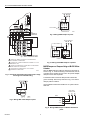
ARD or ZD Dampers
Wire the ARD or ZD Damper to the panel as shown in Fig. 8.
Multiple dampers can be wired in parallel. Use these dampers
on systems up to 2000 cfm.
AOBD Dampers
Wire the AOBD dampers to the panel as shown in Fig. 9. Two
AOBD can be wired in tandem as shown in Fig. 10. More than
two AOBD dampers require the Slave Damper Control Relay
(SDCR).
Fig. 6. Heat pump thermostat with single Y thermostat
wiring.
M20506B
G
C
R
Y
W1
L
W2
E
B
O
COMMON (C) TERMINAL IS USED ONLY BY THERMOSTATS
THAT REQUIRE A COMMON WIRE.
JUMP E TERMINAL TO W1 FOR EMERGENCY HEAT.
LEAVE O/B JUMPER ON TZ-4 DISCONNETED.
TZ-4 THERMOSTAT
CONNECTORS
HEAT PUMP THERMOSTAT WITH
SEPARATE Y1 AND W1
THERMOSTAT WIRING
1
2
3
1
2
3
M20507B
G
C
R
Y1
W1
L
W2
E
B
O
COMMON (C) TERMINAL IS USED ONLY BY THERMOSTATS
THAT REQUIRE A COMMON WIRE.
NORMALLY, CONNECT E ON THERMOSTAT TO W1 ON PANEL.
ALTERNATIVELY, INSTALL JUMPER FROM E TO Y1 ON
THERMOSTAT.
CONNECT O/B TERMOSTAT JUMPER ON TZ-4 PANEL IF
USING O FROM THERMOSTAT; DISCONNECT IF USING B.
TZ-4 THERMOSTAT
CONNECTORS
HEAT PUMP THERMOSTAT WITH
SINGLE Y THERMOSTAT WIRING
1
2
3
1
3
2

TZ-4 TOTALZONE® ZONE CONTROL PANEL
68-0259-1 8
Fig. 7. Heat pump thermostat with 3-stage heat, 2-stage
cool single Y thermostat wiring.
Fig. 8. Wiring ARD or ZD damper to panel.
Fig. 9. Wiring AOBD damper to panel.
Fig. 10. Wiring two AOBD dampers in parallel.
MARD Dampers or Dampers Using an ML6161 Motor
Actuator
Wire the MARD Damper or ML6161 Actuator to the panel as
shown in Fig. 11. These are floating control actuators, but are
controlled as two-position devices on the TZ-4 panel. Multiple
dampers can be wired in parallel.
The ML6161 Motor causes the damper LED to illuminate
green constantly. WIre a relay as shown in Fig. 12 to restore
damper position indication.
Use the MARD or D643 with the ML6161 on systems above
2000 cfm.
Fig. 11. Wiring MARD Damper or ML6161 Actuator to
panel.
M20891
G
C
R
Y1
Y2
L
W3
E
B
O
COMMON (C) TERMINAL IS USED ONLY ON THERMOSTATS
THAT REQUIRE A COMMON WIRE.
ALTERNATIVELY, JUMPER E THERMOSTAT TERMINAL TO Y1 FOR
EMERGENCY HEAT.
CONNECT O/B JUMPER ON TZ-4 WHEN USING O OR DISCONNECT
WHEN USING B FOR CHANGEOVER.
FIELD INSTALLED JUMPER FROM Y2 TO W2 ON PANEL
THERMOSTAT CONNECTIONS.
TZ-4
THERMOSTAT
CONNECTORS
HEAT PUMP THERMOSTAT WITH
SINGLE Y THERMOSTAT WIRING
1
2
3
4
1
4
3
2
4
M6 M4
M1
56
123
Z
X
DAMPER MOTOR
FIELD JUMPER
M19067
MOTOR TERMINALS
4
M6 M4
M1
56
12
3
DAMPER MOTORS
M19068
MOTOR TERMINALS
4 56
123
Z
X
Z
X
FIELD JUMPER
M1 M4
M20136A
ZONE PANEL
CONNECTIONS
M6
CW
COM
CCW
MARD

TZ-4 TOTALZONE® ZONE CONTROL PANEL
9 68-0259-1
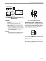
Fig. 12. MARD or ML6161 Damper Motor Actuator using
R8222 Relay wiring.
Transformer
1. Wire the transformers to the panel as shown in Fig. 13.
One 40 VA, 24 Vac transformer controls up to five ARD
or ZD dampers.
2. Connect the transformer to terminals R and C.
3. Add the auxiliary transformer if six to ten ARD or ZD
dampers are used.
a. Wire auxiliary transformer to terminals T1 and T2.
b. It is important that these two transformers be wired
in phase. If they are wired out of phase, the internal
circuit breaker trips and the board de-powers. If this
occurs, remove power, correct the wiring and
restore power to the board.
IMPORTANT
If more than five dampers are required for one zone
or if more than ten dampers are used for the TZ-4,
use the Slave Damper Control Relay (SDCR).
Fig. 13. Wiring transformer(s) to panel.
Discharge Air and Outdoor Temperature Sensors
Wire the C7735A Discharge Air Temperature Sensor (DATS)
to the panel as shown in Fig. 14. The Purge LED (yellow)
flashes in all modes except purge if no DATS is connected to
the TZ-4 or if there is a problem with the DATS or the wiring.
For dual fuel applications, connect the C7089 Outdoor
Temperature Sensor as shown in Fig. 14.
Fig. 14. Wiring C7735A Discharge Air Temperature Sensor
(DATS) to panel.
Add-A-Zone Panel
Remove power from TZ-4 before connecting AZ-1 and AZ-2.
Wire the Add-A-Zone (TAZ-4) Panel to the TotalZone (TZ-4)
Panel as shown in Fig.15. Up to seven TAZ-4 Panels can be
wired to one TZ-4 panel to control up to 32 zones.
COM
CCW
CW
ML6161
R8222 RELAY
ZONE CONTROL PANEL
DAMPER TERMINALS
M20548
A
M6 M4 M1
R
C
R
C
T1
T2
C
R
C
R
24 VAC, 40 VA
Transformer
(Required if
more than
four dampers)
24 VAC, 40 VA
Transformer
DAMPER
XFRM
PANEL
XFRM
M20518
M20519
DATS
DATS
DATS
OT
OT
OT
Sensor

TZ-4 TOTALZONE® ZONE CONTROL PANEL
68-0259-1 10
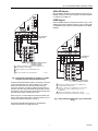
Fig. 15. TotalZone Add-A-Zone wiring.
Conventional Equipment
Wire the heating and cooling equipment to the equipment
terminals on the TZ-4 Panel as shown in Fig. 16.
Conventional Equipment: Set DIP switch 5-1 to on.
Electric Furnaces: Set DIP switch 5-6 to off to energize the fan
with a call for heat.
Hydro-Air: Wire the zone valve or circulator relay to the Rh
and W1 equipment terminals. (If the circulator relay has
powered terminals, remove the Rh Rc jumper.) Set DIP switch
5-6 to off to energize the fan with a call for heat.
Oil Heat: Wire the oil primary T, T terminals to the Rh and W
equipment terminals. (If the oil primary has powered
terminals, remove the Rh Rc jumper.)
Multi-Stage: Wire the equipment as shown in Fig. 16 using the
W2 and W3 terminals for second and third stages of heat.
Wire Y2 for second stage of cooling.
See Single and Multi-Stage Operation in the Operation
section to configure DIP switches 4-1, 4-2, 4-3, and 4-4.
M20362
TotalZone Panel
TotalZone
Add-A-Zone Panel
AZ1
DIP-SWITCHES
AZ2
AZ1
AZ2
AZ1
AZ2
TO NEXT
ADD-A-ZONE
PANEL
54321
O
N

TZ-4 TOTALZONE® ZONE CONTROL PANEL
11 68-0259-1
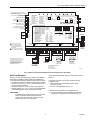
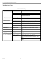
Fig. 16. Wiring conventional heating and cooling equipment to TZ-4 panel.
Heat Pump Equipment
See Fig. 17-22 for heat pump wiring. Refer to manufacturer
instructions for additional wiring details and substitute the
TZ-4 equipment terminals for the thermostat terminals shown.
— Connect the changeover relay to O/B equipment terminal.
— Set switch number 5-7 to on for O (cool) changeover, or to
off for B (heat) changeover.
— Set switch number 5-1 to off for heat pump equipment.
— Set DIP switches 4-1, 4-2, 4-3, and 4-4. See Single Stage
and Multi-Stage Operation in the Operation section.
IMPORTANT
Some heat pump manufacturers (such as York and
Trane) use the B terminal as the transformer
common. Do not connect the common from the
equipment to the zone control panel.
Single-Speed Compressor: Wire the compressor to the Y1
terminal.
If the same heat source is used for auxiliary heat and
emergency heat:
— Wire a jumper from W2 (auxiliary heat) to W1/E
(emergency heat).
— Do not connect W3/AUX. See Fig. 17.
If auxiliary heat is separate from emergency heat:
— Connect the auxiliary heat to W2 jumped to W3/AUX.
— Connect the emergency heat to W1/E. See Fig. 18.
M20520B
ZONE DAMPER MOTORS
M1 - common
M4 - power open
M6 - power closed
HVAC Equipment
DIP SWITCH S4 SETTINGS
1 2ND STAGE OPERATION: TABLE 1
2 2ND STAGE OPERATION: TABLE 1
3 3RD STAGE OPERATION: TABLE 1
4 3RD STAGE OPERATION: TABLE 1
5 STAGE TIMER: TABLE 2
6 STAGE TIMER: TABLE 2
7 STAGE TIMER: TABLE 2
8 UNUSED
DIP SWITCH S5 SETTINGS
1 SYSTEM TYPE
2 DATS LOW LIMIT
3 PURGE TIME
4 PURGE FAN
5 PURGE DAMPER
6 HEAT FAN
7 O/B ENERGIZED
8 DUAL FUEL
LED STATES:
Heat LED Heating Mode
Flashing Heat LED High Limit
Cool LED Cooling Mode
Flashing Cool LED Low Limit
Purge LED Purge Mode
Flashing Purge LED Sensor Failure
Fan LED Fan Mode
EM Heat LED EM Heat Mode
TABLE 1
#1/#3 #2/#4 OPERATION
1 1 STAT
1 0 TIMER
0 1 % ZONES
0 0 OFF
TABLE 2
#5 #6 #7 TIME
1 1 1 5 MIN
1 1 0 10 MIN
1 0 1 15 MIN
1 0 0 20 MIN
0 1 1 30 MIN
0 1 0 40 MIN
0 0 1 50 MIN
0 0 0 60 MIN
ON OFF
1 0
CONV HP
40F 48F
2.0 MIN 3.5 MIN
HVAC PANEL
NO CHG OPEN
HVAC PANEL
COOL HEAT
DISABLED ENABLED
R
H
R
C
W
1
/E
W
2
W
3
/AUX
ZONE LEDs
ON Damper open or opening
OFF Damper closed or closing
MOMENTARY PUSH BUTTONS
Boot – Clears microprocessor
Purge Overide – Bypass Purge Mode
BOOT
PURGE
OVERRIDE
Single Transformer Heating/Cooling
systems require a jumper to be installed
connecting R
H
and R
C
(factory installed).
1 “C” terminal connection
is not required on battery
powered, power stealing,
or some electromechanical
thermostats.
2 Leave jumper disconnected
for conventional thermostats.
R
C
T1
T2
AZ2
AZ1
OFF
ON
EM
Heat
Unoccup
Occup
Zone-
A-Lone
Y
1
Y
2
G
O/B
Heating Transformer
24 VAC
Equip.
Cooling Transformer
First Stage Heating
Second Stage Heating Relay
Third Stage Heating
First Stage Cooling Relay
Second Stage Cooling Relay
Fan Relay
T
his diagram shows the typical
t
hree-stage equipment, thermostat,
a
nd damper motor connections.
F
or specific wiring for other
t
hermostats, damper motors, and
H
VAC Equipment, refer to the
nstallation Instructions.
M6 M4 M1
DATS
DATS
1
Zone 4 Thermostat
C R
C
R
Power-closed
Spring-open
(Model ZD)
Power-closed
Spring-open
(Model ARD)
Power-closed
Spring-open
(Model ARD)
24VAC, 40VA
Transformer
(Required if
more than
four dampers
)
24VAC, 40VA
Transformer
OC
OC
Remote
Zone-A-Lone
Add-A-Zone
Panel(s)
DAMPER
XFRM
PANEL
XFRM
HEAT COOL PURGE FAN EM. HEAT ZONE 1 ZONE 2 ZONE 3 ZONE 4
DIP SWITCH S4 DIP SWITCH S5
1
O
N
2 3 4 5 6 7 81
O
N
2 3 4 5 6 7 8
M6 M4 M1
1
Zone 3 Thermostat
M6 M4 M1
1
Zone 2 Thermostat
456Z
123X
Power-open
Power-closed
(Opposed Blade
Damper Motors)
O/B Y2GW2M6M4M1
W3/
AUXY1
W1/
ERC
Y1 W3/
AUX
W2W1RCY2GLO/B Y1 W3/
AUX
W2W1RCY2GLO/B Y1 W3/
AUX
W2W1RCY2GLO/B Y1 W3/
AUX
W2W1RCY2GLO/B
L
O/B Y2GW2
W3/
AUXY1
W1/
ERC
L
O/B Y2GW2
W3/
AUXY1
W1/
ERC
L
O/B Y2GW2
W3/
AUXY1
W1/
ERC
L
1
Zone 1 Thermostat
ZONE 1
2
Thermostat
DATS
OT
OT
OT
Sensor
130 F
120 F
110 F
140 F
150 F
160 F
MAX. DUCT TEMP.
25 F
20 F
15 F
35 F
30 F
40 F
45 F
DUAL FUEL OT SETTING
Damper
ZONE 2
2
Thermostat Damper
ZONE 3
2
Thermostat Damper
ZONE 4
2
Thermostat Damper

TZ-4 TOTALZONE® ZONE CONTROL PANEL
68-0259-1 12
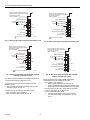
Fig. 17. Wiring single-stage heat pump with auxiliary heat.
Fig. 18. Wiring single-stage heat pump with separate
auxiliary and emergency heat.
Two-speed Compressor: Wire the first stage compressor to
Y1 and the second stage compressor to Y2.
If the same heat source is used for auxiliary heat and
emergency heat:
— Wire a jumper from W3/AUX (auxiliary heat) to W1/E
(emergency heat), see Fig. 19.
If auxiliary heat is separate from emergency heat:
— Wire the auxiliary heat to W3/AUX.
— Wire emergency heat to W1/E, see Fig.20.
Fig. 19. Wiring two-stage heat pump with auxiliary heat.
Fig. 20. Wiring two-stage heat pump with separate
auxiliary and emergency heat.
Dual Fuel Heat Pumps: Install C7089B1000 Outdoor
Temperature Sensor to terminals OT and OT.
— Set outdoor sensor setting to:
— Balance point temperature of heat pump or
— Outdoor temperature above which the heat pump is to
be used and below which the fossil fuel is to be used.
— Set DIP switch number 5-8 to off for dual fuel operation.
— Connect compressor to Y1. See Fig. 21.
— Connect fossil fuel heat to W1/E.
— Connect second stage of fossil fuel to W3/AUX.
— Connect second stage of compressor to Y2. See
Fig. 22.
M20521B
HVAC Equipment
R
H
R
C
W
1
/E
W
2
W
3
/AUX
Single Transformer Heating/Cooling
systems require a jumper to be installed
connecting R
H
and R
C
(factory installed).
Y
1
Y
2
G
O/B
Heating Transformer
24 VAC
Equip.
Cooling Transformer
Auxiliary Heat
Compressor
Reversing Valve
Fan Relay
1
1
FIELD INSTALLED JUMPER.
M20522B
HVAC Equipment
R
H
R
C
W
1
/E
W
2
W
3
/AUX
Single Transformer Heating/Cooling
systems require a jumper to be installed
connecting R
H
and R
C
(factory installed).
Y
1
Y
2
G
O/B
Heating Transformer
24 VAC
Equip.
Cooling Transformer
Emergency Heat
Auxiliary Heat
Compressor
Reversing Valve
Fan Relay
1
FIELD INSTALLED JUMPER.
1
M20523B
HVAC Equipment
R
H
R
C
W
1
/E
W
2
W
3
/AUX
Single Transformer Heating/Cooling
systems require a jumper to be installed
connecting R
H
and R
C
(factory installed).
Y
1
Y
2
G
O/B
Heating Transformer
24 VAC
Equip.
Cooling Transformer
Auxiliary Heat
First Stage Compressor
Second Stage Compressor
Reversing Valve
Fan Relay
1
1
FIELD INSTALLED JUMPER.
M20524
A
HVAC Equipment
R
H
R
C
W
1
/E
W
2
W
3
/AUX
Single Transformer Heating/Cooling
systems require a jumper to be installed
connecting R
H
and R
C
(factory installed).
Y
1
Y
2
G
O/B
Heating Transformer
24 VAC
Equip.
Cooling Transformer
Emergency Heat
Auxiliary Heat
First Stage Compressor
Second Stage Compressor
Reversing Valve
Fan Relay

TZ-4 TOTALZONE® ZONE CONTROL PANEL
13 68-0259-1
Fig. 21. Dual Fuel with single-stage heat pump and single-
stage fossil fuel.
Fig. 22. Dual fuel with two-stage heat pump and
one- or two-stage fossil fuel.
Water Source Heat Pumps
Wire the equipment, as applicable, to the TZ-4 as shown in
Fig. 17-19. Refer to manufacturer instructions for additional
wiring instructions and substitute the TZ-4 equipment
terminals for the thermostat terminals shown.
— Wire first stage compressor to Y1, second stage
compressor to Y2.
— Connect auxiliary heat to W3/AUX and emergency heat to
W1/E.
— If auxiliary heat and emergency heat are the same, wire a
jumper from W1/E to W3/AUX.
— Connect changeover relay to O/B equipment terminal.
— Set DIP switch 5-7 to on for O (cool) changeover, or to off
for B (heat) changeover.
— Set DIP switch 5-1 to off for heat pump equipment.
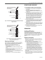
STARTUP AND CHECKOUT
After the installation is complete, verify correct operation:
1. Place the Em Heat switch in the Off (down) position.
2. Place the Zone-A-Lone switch in the Occup/Remote
(up) position.
3. Verify that DIP switches are set correctly. See
Sequence of Operation section and Table 8 for correct
configuration.
4. Power up the TZ-4 and set the thermostats so no zones
are calling. The board then enters the Purge mode
where all dampers open and the fan operates for two or
three and one-half minutes (configurable). (If there is no
Discharge Air Temperature Sensor connected to the
panel, the purge LED flashes in all modes other than
purge.) The damper LEDs are green to indicate the
dampers are open. Press Purge Override button on
panel to exit Purge mode.
5. Set zone one thermostat to heat and raise the setpoint
to call for heat. Verify that the heat LED is red and zone
one damper remains green while the other damper
LEDs turn off.
6. Raise zone two setpoint to call for heat. Lower zone one
setpoint to stop the call for heat to that zone. Verify that
zone one LED turns off and zone two LED turns green.
7. Repeat for zones three and four.
8. Alternately, lower the setpoint to call for cooling. Verify
that the green cool LED illuminates.
OPERATION
Identifying DIP Switches
This panel has two banks of DIP switches, DIP switch 4 (S4)
and DIP switch 5 (S5). Each bank has eight individual
switches that are identified by two numbers; the first number
is the bank number (4 or 5) and the second number identifies
the individual switch. For example, DIP 5-1 is bank 5,
switch 1.
Sequence of Operation
• When there is no call for heat, cool or fan, the board is in
idle mode, no system LEDs are illuminated and the green
damper LEDs indicate open.
• On a call for heat, cool, or fan, the calling zone damper
stays open, and other zone dampers close:
— TZ-4 panel energizes the HVAC equipment and condi-
tioned air is delivered to the calling zone.
— Heat LED (red), cool LED (green), or fan LED (green)
illuminates to indicate equipment operation.
— Fan LED illuminates only on a call for circulation; it
does not illuminate during a call for heat or cool.
— When the call is satisfied, the system enters the Purge
mode. After purge, all dampers return to the Open
position, depending on the setting of DIP switch S5-5.
• Any zone thermostat can call for heating or cooling. If there
are co-existing calls for heat and cool, the panel accepts
the first call.
• Once that call is satisfied, or a maximum of 20 minutes has
elapsed, the panel switches to allow the opposite call after
completing Purge mode.
M20525
A
HVAC Equipment
R
H
R
C
W
1
/E
W
2
W
3
/AUX
Single Transformer Heating/Cooling
systems require a jumper to be installed
connecting R
H
and R
C
(factory installed).
Y
1
Y
2
G
O/B
Heating Transformer
24 VAC
Equip.
Cooling Transformer
First Stage Fossil Fuel
First Stage Compressor
Reversing Valve
Fan Relay
M20526
A
HVAC Equipment
R
H
R
C
W
1
/E
W
2
W
3
/AUX
Single Transformer Heating/Cooling
systems require a jumper to be installed
connecting R
H
and R
C
(factory installed).
Y
1
Y
2
G
O/B
Heating Transformer
24 VAC
Equip.
Cooling Transformer
First Stage Fossil Fuel
Second Stage Fossil Fuel
First Stage Compressor
Second Stage Compressor
Reversing Valve
Fan Relay

TZ-4 TOTALZONE® ZONE CONTROL PANEL
68-0259-1 14
Purge Mode
At the end of every call for heat or cool, the panel enters a
Purge mode that holds open the calling zone damper for two
(default) or three and one-half minutes.
During this time, the panel or the HVAC equipment can be
configured to operate the fan. The Purge LED lights to signal
that the system is in the Purge mode. Pressing the purge
override button overrides the Purge mode.
Unless there is a new call for heat or cool during the Purge
mode, all dampers are moved to the Open position at the end
of purge.
The panel can be configured to open all dampers during the
purge mode.
Individual Zone Fan Control
When all zones are satisfied, the fan switch of each
thermostat controls the fan operation for that zone.
— When the fan switch is in the On position, the fan is
energized, and dampers close to zones where fan switch is
in Auto position.
— During a call for heat or cool at this time, the circulation
mode ceases, and the heat or cool call is honored.
— When the zone calling is satisfied, the circulation call
resumes.
Single and Multi-Stage Operation
The panel can control up to three stages of heating and two
stages of cooling:
— First stage is energized by the thermostat.
— Second stage of heating or cooling and third stage of
heating can be energized by the thermostat, timer, or the
percentage of zones calling. (For instance, first and second
stage of heat and cool can be thermostat energized and
third stage heat can be configured for timer energizing.)
— See Tables 5 and 6 for second and third stage
configuration. Note that second and third stage can be
controlled differently. Set stages not used to Off.
DIP Switch bank 4, switches 1-4, are used to configure the
staging method:
— Switches 1 and 2 configure second stage control. See
Table 4.
— Switches 3 and 4 configure third stage control. See Table.
5.
— When stage two or three is not used, disable that stage by
turning off the corresponding switches.
Single Stage
If equipment is single stage, set bank 4, DIP switches 1-4 Off:
THERMOSTAT-CONTROLLED STAGES
Use a thermostat that energizes W2 and Y2 for second stage
of heat and cool, and W3 for third stage of heat. Configure for
thermostat as shown in Tables 4 and 5.
TIMER-CONTROLLED STAGES
— The Timer energizes second stage of heat or cool after the
first stage begins calling for the set amount of time.
— The third stage of heat is energized once the second stage
of heat is calling for the set amount of time.
— Second and third stages remain energized until the call for
heat or cool is satisfied.
See Table 6 for stage timer configuration of DIP switch bank 4,
switches 5, 6, and 7.
PERCENTAGE OF ZONES CALLING—CONTROLLED STAGES
Percentage of zones calling energizes second or third stage
based on the percentage of zones called for heat or cool on
the TZ-4 and TAZ-4.
The percentage of zones necessary to turn stages two and
three on and off:
DIP Switch
Number
Status Purge Operation
5-3 Off 3.5 minutes
5-3 On 2 minutes
5-4 Off Panel control of fan in
purge
5-4 On HVAC control of fan
in purge
5-5 Off All dampers open
during purge
5-5 On Damper positions
unchanged during
purge
DIP Switch
Number
Stage Status
4-1
2
nd
Stage
Off
4-2
2
nd
Stage
Off
4-3
3
rd
Stage
Off
4-4
3
rd
Stage
Off
Stage On Off
Stage 2 Heat >33% </=25%
Stage 2 Cool >33% </=25%
Stage 3 Heat >66% </=56%

TZ-4 TOTALZONE® ZONE CONTROL PANEL
15 68-0259-1
HEAT PUMP OPERATION
The panel can control single- or two-stage heat pumps with or
without auxiliary heat. Set DIP switch 5-1 to Off for heat pump
control. This energizes equipment terminal Y1 on a call for
first stage heat or cool. If second stage is configured to
operate with DIP switch 4-1 and 4-2, Y2 energizes to call for
second stage compressor. When in heat pump mode, the
panel energizes the fan with a call for heat and a call for cool.
Configure DIP switch 5-7 for correct changeover valve control.
See Table 7.
DUAL FUEL OPERATION
The panel can control a heat pump and a fossil fuel furnace in
a dual-fuel application. A C7089B1000 Outdoor Temperature
Sensor is wired to the OT and OT terminals on the TZ-4 to
switch the panel from heat pump to fossil fuel operation. DIP
switch 5-8 is set to Off to enable dual-fuel operation.
The dual-fuel OT setting (see Fig. 16 for location) is set to the
outdoor temperature that locks out the heat pump and uses
the fossil fuel mode. The fan is energized by the panel for two
minutes after the changeover and the Em Ht LED illuminates
when in the fossil fuel mode.
IMPORTANT
A C7089B1000 Outdoor Temperature Sensor and a
C7735A1000 Discharge Air Temperature Sensor are
required for dual fuel operation.
Table 4. DIP Switch Bank 4, Stage 2 Configuration.
Operation Switch 4-1 Switch 4-2
Thermostat On On
Timer On Off
% of Zones Off On
Off Off Off
Table 5. DIP Switch Bank 4, Stage 3 Configuration.
Operation Switch 4-3 Switch 4-4
Thermostat On On
Timer On Off
% of zones calling Off On
Off Off Off
Table 6. DIP Switch Bank 4, Stage Timer Configuration.
Time
DIP Switch
4-5
DIP Switch
4-6
DIP Switch
4-7
5 minutes On On On
10 On On Off
15 On Off On
20 On Off Off
30 Off On On
40 Off On Off
50 Off Off On
60 Off Off Off
Table 7. DIP Switch Bank 5 Settings and Functions.
DIP Switch Function On (Default) Off
5-1 System Type Conventional Heat Pump
5-2 DATS low limit. 40°F 48°F
5-3 Purge mode timing. Two minutes. Three and one-half minutes.
5-4 Fan control during purge. HVAC controlled. Panel controlled.
5-5 Damper control during purge Last zone(s) calling open. All dampers open.
5-6 Fan control in heat. Fan controlled by panel in cool
and HVAC equipment in heat.
Panel in heat and cool controlling
fan.
5-7 Operation of O/B heat pump
changeover equipment terminal.
O/B equipment terminal is
energized in cool (O).
O/B equipment terminal is
energized in heat (B).
5-8 Dual fuel operation. Disabled. Enabled.

TZ-4 TOTALZONE® ZONE CONTROL PANEL
68-0259-1 16
Thermostat Operation
Conventional Thermostats
Conventional (R,W,Y,G) heat/cool thermostats can be used
with the TZ-4 to control single or multi-stage gas, electric or oil
systems and heat pumps with auxiliary heat.
The panel can be configured to control second stage heat and
cool and third stage heat using a 5-60 minute timer, or staging
can be controlled by the percentage of zones calling.
When using conventional thermostats on heat pump
applications, set DIP switch 5-1 to Off for heat pump
equipment. Set DIP switch 5-7 for correct reversing valve
operation. See Table 7.
Heat Pump Thermostats
HEAT PUMP THERMOSTATS WITH SINGLE Y OUTPUT
Thermostats that have a single Y terminal for first stage heat
and cool and those with separate Y1 and W1 can be used.
Thermostats of either wiring type can be used on any zone.
For thermostats with a single Y, the reversing valve wire must
be connected to O/B:
— Connect the thermostat Y terminal to Y1 on the panel.
— If the thermostat energizes O on a call for cool, connect the
O/B jumper located near the thermostat wiring terminals.
— If the thermostat energizes B on a call for heat, leave the
O/B jumper disconnected.
HEAT PUMP THERMOSTATS WITH SEPARATE Y1 AND W1
TERMINALS
Heat pump thermostats with separate Y1 and W1 terminals for
first stage heat and cool are wired to Y1 and W1/E. Leave the
O/B jumper, located near the thermostat wiring terminals,
disconnected.
Emergency Heat Control
Emergency heat is defined as using an auxiliary heat source
without using the heat pump. When the Em Heat switch is in
the emergency heat position, the heat pump is locked out and
calls for heat are sent to the W1/E equipment terminal for
fixed stage emergency heat. Second stage emergency heat
energizes equipment terminals W3/Aux. Second stage
emergency heat is configured with DIP switch S41 and 2.
When the panel is in the heat pump mode, W1/E is energized
only in emergency heat.
A recommended heat pump thermostat can also control
emergency heat from the thermostat system switch. See
Table 1.
Multi-Stage Thermostats
Use multi-stage thermostats to control up to three stages of
heat and two stages cool with the W1/E,W2, W3/AUX, Y1,
and Y2 thermostat terminals.
Manual and Automatic Changeover Thermostats
Manual or automatic changeover thermostats can be used.
The panel determines the call for heat or cool based on which
was called for first. Subsequent calls for heat or cool are
honored when the initial call is satisfied, or 20 minutes has
elapsed.
Rebooting Microprocessor
To reset the panel, press and release the Boot button.The
system reboots and enters the Purge mode.
Discharge Air Temperature Sensor
The C7735A1000 Discharge Air Temperature Sensor (not
included) is a supply-duct-mounted temperature probe used
to control capacity and prevent high limit or coil-icing. The
sensor attaches to the two DATS terminals on the panel.
When a high or low limit is reached, the panel shuts off the
equipment and keeps the fan operating for 2-1/2 minutes.
After this time, it re-energizes the equipment after the
discharge air recovers by 10 degrees. When the DATS
exceeds the high or low limit, the Heat (red) or Cool (green)
LED flashes.
Set the temperature from 110°F to 160°F. See Fig. 23. The
recommended setting for fossil fuel/ electric systems is 160°F
(default factory setting). For heat pump systems, the
recommended setting is 120°F. When using a heat pump
with dual fuel activated (DIP 5-8), the high limit will auto-
matically be set for 120 degrees when the outputs call for
compressor only operation. When the outputs call for non-
heat pump operation, the high limit will be set to the adjustable
110° to160°F setting.
The cooling temperature limit can be set at 40°F or 48°F.
Fig. 23. DATS high-limit temperature dial.
IMPORTANT
Be sure the Discharge Air Temperature Sensor wir-
ing does not run parallel with line voltage wiring
unless more than 12 in. of separation exists or
shielded cable is used.
130 F
MAX DUCT
TEMP
M19079
A
120 F
110 F
140 F
150 F
160 F

TZ-4 TOTALZONE® ZONE CONTROL PANEL
17 68-0259-1
Use DIP switch 5-2 to change cooling limit settings:
Zone-A-Lone Switch
When the Zone-A-Lone switch is in the occupied (up) position
and the OC/OC terminals are not used, the system functions
as a zone control system.
When switched to the unoccupied (down) position, all
dampers are opened and all requests for heat, cool, or fan,
except from zone one, are not honored.
The zone one thermostat becomes the controlling thermostat
for the entire system. During long unoccupied periods, one
thermostat can be set back instead of adjusting each zone
thermostat in the building.
The T8601D2027 and T8611G2051 include two OC terminals.
When wired to the TZ-4 OC terminals, and with the Zone-A-
Lone switch in the occupied (up) position, the board enters the
unoccupied mode during the Leave and Sleep programs. This
feature requires two extra wires to the Zone 1 thermostat.
Circuit Breaker Protection
A built-in thermal circuit breaker protects the TotalZone panel.
This circuit breaker protects the panel against shorts in the
thermostat and damper wiring. It does not protect against
shorts in the wiring of the HVAC equipment into the panel.
When the circuit breaker is tripped, none of the LEDs
illuminate and the yellow rectangular component located left
of the R and C terminals is hot to touch. Remove power to the
panel for at least five minutes to allow the circuit breaker to
cool off and reset. To eliminate the short, verify the dampers
and thermostat wiring.
Fan On In Heat
The system blower can be set to come on with a call for heat
as required for hydro-air or electric heat systems. Set the
blower function using DIP switch 5-6.
When DIP switch 5-1 is set to Off for heat pump control, the
panel brings the fan on with a call for heat and a call for cool.
TotalZone Add-A-Zone Panels
Using TotalZone Add-A-Zone Panels, the system can be
expanded to up to 32 zones using TAZ-4 Add-A-Zone panels.
Two wires connect the AZ1 and AZ2 terminals on the TZ-4 to
the matching terminals on the TAZ board(s).
See Fig. 15 and the TAZ installation instructions for more
information.
Dip Switch Status
Cooling Temperature
Limit
5-2 On 40°F
5-2 Off 48°F
DIP Switch 5-6 Fan Control
On HVAC system
Off Fan on in heat

TZ-4 TOTALZONE® ZONE CONTROL PANEL
68-0259-1 18
TROUBLESHOOTING
Table 8. Troubleshooting.
Symptom Possible Cause Action
No LEDs are Illuminated No power to the board. Check for 24 Vac (±10%) across R and C.
Transformers out of phase If 48 Vac across R and T1, reverse T1 and T2 wires.
Shorted wire. Check thermal circuit breaker. If hot, a short exists in
thermostat or damper wiring.
Damper LEDs on, but no
other LEDs illuminated.
Insufficient voltage. Check for 24 Vac (±10%) across R and C.
Incorrect configuration. Check jumpers and DIP switches for correct configuration.
Heat pump operates
incorrectly or not at all.
Incorrectly wired. Verify equipment and thermostat terminal wiring.
Incorrectly configured. Verify DIP switch configuration.
Verify position of O/B thermostat type jumper.
Erratic Operation Emergency Heat switch
on.
Turn off (down) Emergency Heat switch.
Zone-A-Lone Feature on. Turn off (up) Zone-A-Lone.
Heat LED flashing. High limit reached. LED stops flashing with ten-degree fall and 2-1/2 minute
delay.
Cool LED flashing. Low limit reached. LED stops flashing with ten-degree rise and 2-1/2 minute
delay.
Purge LED flashes
continuously.
DATS or OT problem or not
connected.
Verify that DATS and OT (if any) are connected and wired
correctly.
Add-A-Zone not operating. Incorrectly configured. Verify DIP switch settings on the TAZ panels.
Incorrectly wired.
Check AZ1and AZ2 for correct wiring.
Verify that a separate transformer is used for each TAZ-4
panel.
Be sure that AZ1 and AZ2 are at least 12 in. from line voltage
wiring.

TZ-4 TOTALZONE® ZONE CONTROL PANEL
19 68-0259-1
Table 9. LED Indicators.
LED Color Illuminated Not Illuminated Flashing
Heat Red Heat call. No heat calls. High limit reached.
Cool Green Cool call. No cool calls. Low limit reached.
Purge Amber Purge mode. Not in Purge mode. • DATS failure: slow flash.
• OT failure: fast flash.
• DATS and OT failure:
alternating fast and slow flash.
Fan Green Fan only call. No fan only call. —
EM Heat Red Emergency Heat mode or
dual-fuel mode.
Not in emergency Heat mode or
dual-fuel mode.
—
Zones
1,2,3.4
Green Damper is open or
opening.
Damper is closed or closing. —

68-0259-1 G.H. Rev. 12-02 www.honeywell.com/yourhome
Automation and Control Solutions
Honeywell Honeywell Limited-Honeywell Limitée
1985 Douglas Drive North 35 Dynamic Drive
Golden Valley, MN 55422 Scarborough, Ontario
M1V 4Z9
TZ-4 TOTALZONE® ZONE CONTROL PANEL
-
 1
1
-
 2
2
-
 3
3
-
 4
4
-
 5
5
-
 6
6
-
 7
7
-
 8
8
-
 9
9
-
 10
10
-
 11
11
-
 12
12
-
 13
13
-
 14
14
-
 15
15
-
 16
16
-
 17
17
-
 18
18
-
 19
19
-
 20
20


Ask a question and I''ll find the answer in the document
Finding information in a document is now easier with AI
Related papers
-
Honeywell MINI-ZONE-2 MM-2 MASTERTROL User manual
-
-
-
Honeywell CT3200 series User manual
-
Honeywell C7735A1000 User manual
-
Honeywell HZ432 User manual
-
-
-
Honeywell W8835 User manual
-
Other documents
-
White Rodgers 1C20-101 Supplemental Wiring
-
Braeburn 140221 2 Zone Control Panel User manual
-
Home Automation RC-1000 User manual
-
Braeburn 140332 User manual
-
Broan PCMMP3 Zoning System Installation guide
-
-
-
Aprilaire 8028 User manual
-
 HAI RC-2000 User manual
-
Lux Products CH200SA User manual
