
PAGE 1
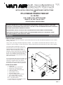
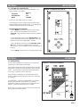
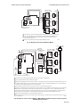
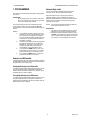
1.2 THIS KIT INCLUDES:
Control box
12' long heat tape, w/ thermostat
30' long roll of insulation wrap
Copper 1/2" NPT thermowell w/clip
Cord grip connector
Linear platinum sensor
2' of 3/8" flexible conduit
Three (3) seal fittings for connectors
3/8" conduit straight connector
3/8" 90 degree elbow connector
1" x 1/2" NPT bushing
Four (4) #12-14 x 1" self tapping screws
Heat Condictive Compound
February 2008
P/N 32-0228
REV . B
INSTALLATION, OPERATION & MAINTENANCE INSTRUCTIONS
FOR
FP-4 FREEZE PROTECTION KIT
P/N 83-0763
FOR TURBO-COOL AFTERCOOLERS
MODELS
AC-140-7 thru AC-220-7
(230V-3PH-60Hz & 460V-3PH-60Hz)
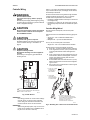
WARNING
BEFORE STARTING INSTALLATION OR MAINTENANCE PROCEDURES, TURN OFF ELECTRICAL POWER AND
COMPLETELY DEPRESSURIZE THE AFTERCOOLER. FAILURE TO HEED THIS WARNING MAY RESULT IN SERIOUS
PERSONAL INJURY AND/OR DAMAGE TO THE UNIT.
NEVER REMOVE, REPAIR, OR REPLACE ANY ITEM ON THE AFTERCOOLER WHILE IT IS PRESSURIZED.
WHEN INSTALLING THIS KIT, ALWAYS COMPLY WITH THE NATIONAL ELECTRICAL CODE AND ALL OTHER
APPLICABLE FEDERAL, STATE AND LOCAL CODES.
SECTION 1 INTRODUCTION
1.1 DESCRIPTION OF OPERATION
The FP-4 freeze protection kit is designed to prevent aftercooler freeze up when the ambient temperature is near or below
freezing, 32
o
F (0
o
C).
The FP-4 has a two stage solid state temperature controller. The controller is mounted inside a Nema 4 enclosure. The
controller is used to energize a control relay which is rated to handle the load of the aftercooler fan at the various voltages.
The linear platinum temperature sensor and
thermowell mount into the piping between the
outlet manifold of the aftercooler and the
separator. When the temperature of the com-
pressed air system at the aftercooler outlet falls
to 35
O
F, the controller will automatically turn off of
the fan. The controller is set for a 10
o
F dead
band to prevent rapid cycling (fan will turn off at
35
O
F and on at 45
o
F).
A 12 foot heat tape and 30 feet of insulation wrap
are provided to wrap around the separator. The
heat tape is equipped with its own internal
temperature control. The heat tape and insula-
tion will provide additional freeze up protection.
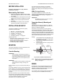
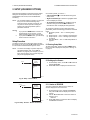
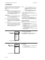
FIGURE 1-A ITEMS INCLUDED WITH THIS KIT
1.
2.
3.
4.
5.
6.
7.
8.
9.
10.
11.
12.
13.

PAGE 2
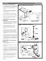
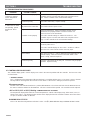
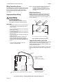
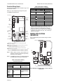
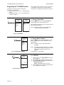
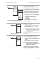
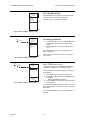
2.1 MOUNTING THE CONTROL BOX
The control box should be mounted near the
outlet manifold of the aftercooler. Make sure
that the control box is close enough so that all
components can reach the box when in-
stalled.
Drill the four pilot holes in the mounting
surface using a 1/8" drill. Reference Figure 2-
A for dimensions.
The control box will be mounted with the
hinged side of the enclosure on the bottom.
Fasten the controller in place using the four
(4) #12-14 x 1" long self-tapping screws
supplied with the kit.
SECTION 2 INSTALLATION
FIGURE 2-A MOUNTING THE CONTROL BOX
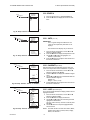
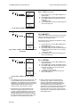
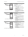
FIGURE 2-B MOUNTING THE THERMOWELL
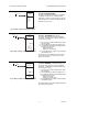
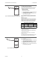
FIGURE 2-C INSTALLING THE HEAT TAPE AND INSULATION
2.2 INSTALLING THE SENSOR AND
THERMOWELL
A 1/2" NPT or larger connection in the system
piping between the outlet of the aftercooler
and the inlet of the separator is required for
the thermowell and sensor.
Thread the thermowell and the 1" x 1/2"
bushing (if required) into a connection
between the aftercooler outlet and the
separator.
Place some heat conductive compound into
the thermowell. Place the sensor into the
thermowell and fasten it in place using the
clip supplied with the thermowell. Reference
Figure 2-B.
Install the cord grip connector into the control
box as shown in Figure 2-B. Push the sensor
cable through the connector. Wire the sensor
cable to the controller circuit board terminals
as shown in Figure 2-F. Tighten the grip nut
on the connector.
2.3 INSTALLING THE HEAT TAPE AND
INSULATION
Install the cord grip on the control box as
shown in Figure 2-C.
Cut the plug end off the heat tape. Strip back
the wires.
Push the wire end of the heat tape through
the connector. Allow enough cord inside the
box for wiring. Connect the heat tape to the
proper terminals in the control box as shown
in FIGURES 2-F. Tighten the grip nut on the
connector.
Run the heat tape to the separator. Wrap the
heat tape around the separator as shown in
Figure 2-C. Do not overlap the tape.
Wrap the insulation around the piping and
heat tape as shown in Figure 2-C.

PAGE 3
SECTION 2 INSTALLATION
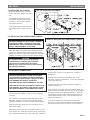
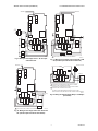
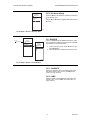
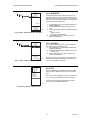
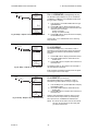
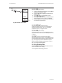
2.4 INSTALLING THE CONDUIT
Install the straight conduit connector
on the control box. Reference Figure
2-D.
The supplied conduit will be used to
run between the aftercooler and the
control box. Connect the conduit to
the straight connector.
Install the 90 degree elbow connector
on the aftercooler. Reference Figure
2-D.
FIGURE 2-D INSTALLING THE CONDUIT
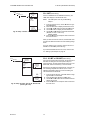
2.5 INSTALLING THE TRANSFORMER JUMPERS
WARNING
BEFORE STARTING THIS PROCEDURE, TURN OFF
ELECTRICAL POWER. FAILURE TO HEED THIS
WARNING MAY RESULT IN SERIOUS PERSONAL
INJURY AND/OR DAMAGE TO THE UNIT.
This kit was designed to operate at 230V-3PH-60Hz or
460V-3PH-60Hz. Two jumpers were shipped inside the
control box. They must be installed on the transformer
before connecting the power to the control box. Install the
jumper(s) as shown in Figure 2-E for the desired voltage.
CAUTION
It is important that this procedure be properly
completed before continuing with installation.
This kit will not operate without the jumpers.
Damage to the control box will occur if the jumpers
are improperly installed.
FIGURE 2-E INSTALLING THE TRANSFORMER JUMPERS
2.6 ELECTRICAL CONNECTIONS
WARNING
BEFORE STARTING INSTALLATION PROCEDURES
OR ATTEMPTING TO MAKE ANY WIRING CHANGES,
TURN OFF ELECTRICAL POWER. FAILURE TO HEED
THIS WARNING MAY RESULT IN SERIOUS
PERSONAL INJURY AND/OR DAMAGE TO THE UNIT.
WHEN INSTALLING THIS KIT ALWAYS COMPLY WITH
THE NATIONAL ELECTRICAL CODE AND ALL OTHER
APPLICABLE FEDERAL, STATE AND LOCAL CODES.
A 7/8" hole in the top right side of the control box is provided
for incoming power conduit. The hole can be enlarged if
necessary.
The control box is designed for 230V-3PH-60Hz or 460V-
3PH-60Hz operation. The transformer jumpers must be
installed as outlined in Section 2.5 for the desired voltage.
Make the necessary wiring runs and connections for the
main power supply.
Remove the junction box cover on the aftercooler for access
to the junction box. Make the necessary wiring runs through
the conduit from the aftercooler to the control box. Fasten the
conduit to the connector on the aftercooler. Reference
FIGURE 2-D.
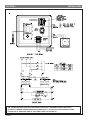
Make the wire connections at the junction box on the
aftercooler. Reference FIGURE 2-F. Fasten the junction box
cover to the aftercooler.
Complete the wire connections inside the controller as
shown in FIGURE 2-F.
Once all wiring connections have been properly made, the
rotation of the fan should be checked. The fan must rotate in
the proper direction for maximum performance. Reference
the operator's manual supplied with the aftercooler for the
correct rotation direction. Also, check the aftercooler for a
rotation direction label.
To check the rotation, turn on the power supply to the
aftercooler. If the fan does not rotate in the proper direction,
any two of the power leads to the motor can be switched.

PAGE 4
IMPORTANT
THE FAN MOTOR MUST ROTATE IN THE CORRECT DIRECTION. REFERENCE THE AFTERCOOLER
OPERATOR'S MANUAL FOR PROPER ROATION DIRECTION. IF IT DOES NOT, THE ROTATION CAN BE
CORRECTED BY SWITCHING TWO OF THE POWER LEADS TO THE MOTOR.
SECTION 2 INSTALLATION
FIGURE 2-F CONTROL BOX COMPONENT LAYOUT and WIRING DIAGRAM

PAGE 5
SECTION 2 INSTALLATION
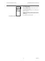
2.7 SETTING THE CONTROLLER
The controller was factory set for normal operation. The
factory settings are as follows:
RELAY 1
SET POINT 35
O
F
DIFFERENTIAL 10
O
F
MODE COOLING
Turn on the main power to the FP-4 control.
If the settings have been changed, set them to the factory
settings following the procedures below . The controller will
retain the setting if the power is disconnected.
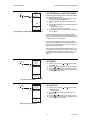
PROGRAMMING PROCEDURES
1. Press MENU key, then press RIGHT arrow key three
times. Use the UP and DOWN arrow to select the
SETPOINT. Press the RIGHT arrow to store the setpoint in
memory.
2. Press the RIGHT arrow to set the DIFFERENTIAL. Use
the UP and DOWN arrow to set the differential. Press the
RIGHT arrow to store the differential in memory.
3. Press the RIGHT arrow key to set the HEATING / COOL-
ING mode. Use the UP or DOWN arrow to select the
desired mode. Press the RIGHT arrow to store the mode in
memory.
4. Press RIGHT arrow three times to exit the program mode.
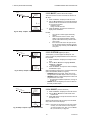
SECTION 3 OPERATION
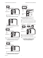
3.1 OPERATION
Once the kit is installed and set properly, just energize the
controller and it will operate automatically.
The controller will turn off half of the aftercooler fan when the
temperature of system air at the outlet of the aftercooler falls
to 35
O
F. The fan will turn on when the system temperature
rises to 45
o
F. Reference chart in Figure 3-A .
The heat tape is controlled by its own internal thermostat.
Power is supplied to the heat tape as long as the control box
is energized.
The temperature controller is equipped with a LCD display.
During normal operation when the fan are operating,
(temperature above set points) the sensor temperature and
RELAYS 1 ON will be displayed on the controller.
NOTE: The cover on the control box must be opened to view
the temperature controller display.
FIGURE 3-A OPERATION SEQUENCE
FIGURE 2-G CONTROLLER DISPLAY

PAGE 6
4.2 CONTROLLER ERROR CODES
The controller display panel is used to display error codes in the event of problems with the controller. The four error codes
are listed below.
-- -SENSOR FAILURE
The "--" displayed for the temperature indicates that there is a problem with the sensor. The sensor is open or shorted.
All relays will be de-energized in the event of a sensor failure. If the sensor is damaged, it must be replaced.
EE-EEPROM FAILURE
The "EE" error code indicates that there is a problem with EEPROM. The values read back from the EEPROM are not
the same as what was written into the EEPROM. This error cannot be field repaired. The controller must be replaced.
-60°F or 270°F (-51°C or 132°C) Blinking - TEMPERATURE OUT OF RANGE
The temperature display blinks when the sensed temperature is outside of the display range, below -60°F (-51°C) or
above 270°F (132°C). The displayed value remains at the display limit and the controller continues to function unless
an open or shorted condition is detected.
BLINKING RELAY STATUS
This occurs when the Relay Minimum Off Time is active. The (ñ ) blinks while the relay's minimum off time is active.
SECTION 4 TROUBLESHOOTING
4.1 TROUBLESHOOTING PROCEDURES
PROBLEM POSSIBLE CAUSES
SOLUTIONS
1. Aftercooler fan motor
continues to operate,
system temperature
below 35
O
F.
Check the controller settings as outlined in Section 2.7. The
controller may be set in the heat mode or the set points set too
low. Set the controller to the recommended settings.
Check the control relay. Replace if faulty.
2. Aftercooler fan motor
not operating, system
temperature above
45
O
F.
Check main electrical power source.
Check the transformer. Make sure that the jumpers on the
transformer are properly installed. Reference Section 2.5.
Check the fuses on the transformer.
Controller not set properly
Control relay faulty
No power to the control box
No power to the controller
Controller not set properly
Check the controller settings. If the controller is properly set, check
the main power source.
Check the controller display for error codes. Section 4.2 outlines
what the error codes indicate and the necessary steps.
Sensor failure
If the sensor is faulty a "--" will be displayed for the temperature on the
controller display. Refer to Section 4.2 for further details. If the
sensor is faulty, it must be replaced.
Control relay faulty
Check the control power at the relay coil. Check the relay for proper
operation. Replace if faulty.
Check the controller settings as outlined in Section 2.7. The
controller may be set in the heat mode or the set points set too
high. Set the controller to the recommended settings.
Controller failure

PAGE 7
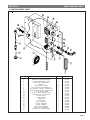
SECTION 5 REPLACEMENT PARTS
5.1 REPLACEMENT PARTS
ITEM NO.
1
2
3
4
5
6
7
8
9
11
12
13
14
15
16
17
18
19
20
21
22
23
DESCRIPTION
12' LONG HEAT TAPE
30' ROLL OF INSULATION WRAP
1/2" NPT THERMOWELL w/CLIP
CORD GRIP CONNECTOR
SENSOR
3/8" FLEXIBLE CONDUIT
SEAL FITTING FOR CONNECTOR
3/8" CONDUIT STRAIGHT CONNECTOR
3/8" 90
O
ELBOW CONDUIT CONNECTOR
1" X 1/2" NPT BUSHING
#12-14 x 1" SELF TAPPING SCREW
TEMPERATURE CONTROLLER
MOTOR RELAY
TRANSFORMER
1 AMP FUSE
.6 AMP FUSE
GRAY TERMINAL
YELLOW TERMINAL
GREEN TERMINAL
END CLAMP TERMINAL
JUMPER FOR TERMINAL
JUMPER FOR TRANSFORMER
PART NO.
26-8151
26-0712
29-0325
26-5618
26-7186
26-0875
26-0883
26-1068
26-1078
14-0402
28-1286
26-7185
26-0919
26-5637
26-5336
26-5638
26-0380
26-0382
26-0384
26-0388
26-0686
26-5663
QTY
1
1
1
2
1
2 FT
3
1
1
1
4
1
1
1
1
2
2
2
2
2
2
2

PAGE 8
MAKING COMPRESSED AIR AND GAS WORK BETTER SINCE 1944.
YOUR VAN AIR REPRESENTATIVE IS:
NAME:
COMPANY:
ADDRESS:
CITY: STATE: ZIP:
PHONE: FAX:
ATTACH BUSINESS CARD HERE
2950 Mechanic Street
Lake City, PA 16423 USA
Phone: 800/840-9906
Service Fax: 814/774-0778
Order Entry Fax: 814/774-3482
www.vanairsystems.com
SECTION 6 WARRANTY
PER VAN AIR TERMS AND CONDITIONS OF SALE

E4436
INSTALLATION INSTRUCTIONS
62-0254-03
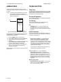
T775A/B/M Series 2000 Electronic
Stand-Alone Controllers
PRODUCT DESCRIPTION
The T775 electronic stand-alone controllers are the next
generation of commercial and agricultural controls
capable of remote sensing of temperature and providing
switched and/or proportional outputs to various types of
loads.
Five models have analog (modulating) outputs for
actuator and motor control, and NEMA-4 weatherproof
enclosures are available for wet environments.
IMPORTANT
Each T775A/B/M controller is an operating
control, not a limit or safety control. If used in
applications requiring safety or limit controls, a
separate safety or limit control device is
required.
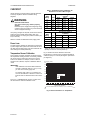
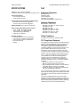
Table 1. T775A/B/M Controller Configurations.
Controller
Model
a
a
All models include a digital input for use with the disable or setback option.
Description Replaces
SPDT
Relay
Outputs
Analog
(Mod)
Outputs
b
b
The modulating (analog) outputs are 4-20 mA, 0-10 Vdc, 2-10 Vdc, or Series 90 selectable.
Floating
Outputs
c
c
Each floating output eliminates two SPDT relays.
Sensor
Inputs
Nbr of
Sensors
Included Enclosure
T775A2009 Standard T775A1001 1 None None 1 1 NEMA 1
T775B2016 Standard N/A 2 None 1 2 1 NEMA 4X
T775B2024 Standard T775C1009 T775D1008 4 None 2 2 1 NEMA 4X
T775B2032 Standard T775A1019 T775B1000 2 None 1 2 1 NEMA 1
T775B2040 Standard T775A1027 T775A1035
T775B1018 T775B1026
T775B1042
4None 2 2 1NEMA 1
T775M2006 Modulating N/A None 2 N/A 2 1 NEMA 1
T775M2014 Modulating T775G1005 T775G1013
T775G1021 T775G1039
42N/A
2
d
d
These models can support a high/low modulating limit at Sensor B for temperature control at Sensor A.
1 NEMA 4X
T775M2022 Modulating N/A 2 2 N/A
2
d
1 NEMA 4X
T775M2030 Modulating T775E1114 T775F1022
T775F1055 T775F1089
42N/A
2
d
1 NEMA 1
T775M2048 Modulating T775E1015 T775E1023
T775E1056 T775E1064
T775E1098
22N/A
2
d
1 NEMA 1

T775A/B/M SERIES 2000 CONTROLLER PRODUCT DESCRIPTION
62-0254–03 2
Temperature Sensors
a
The controller accepts 1,097 Ohms PTC at 77°F (25°C):
• 50021579-001 – Standard sensor (included with all
models except NEMA 4X models)
• T775-SENS-WR – Water resistant with 5 foot leads
(included with NEMA 4X models)
• T775-SENS-WT – Watertight with 6 foot lead
• T775-SENS-OAT – Outdoor air temperature sensor
• C7031D2003 – 5 inch immersion sensor with wiring
box (use immersion well; P/N 50001774-001)
• C7031J2009 – 12 foot duct averaging sensor with
wiring box
• C7046D1008 – 8 inch duct probe with mounting flange
• C7100D1001 – 12 inch fast response, duct averaging
sensor with flange
• C7130B1009 – Room mount sensor
Accessories
• 107324A – Bulb Holder, duct insertion
• 107408 – Heat Conductive Compound, 4 ounce
• 50001774-001 – Immersion Well, stainless steel 304,
1/2 in. threading
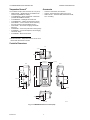
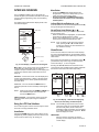
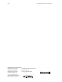
Controller Dimensions
Fig. 1. T775A/B/M dimensions in inches (mm).
a
See form 62-0265 – Temperature Sensors for the T775
Series 2000 Stand-alone Controller
4 13/32 (112.1)
1/2 (12.4)
3 31/32 (101)
7 23/32
(196)
8 5/32
(207.1)
2 15/16 (74)
7/8 (22.5)
1 (25.5)
4 1/16 (103.4)
4 1/16 (103.4)
1/64 (3.8)
2 11/16 (68.1)
7/8 (22.5)
2 13/16 (71.8)
7/8 (22.5)
1 (25.5)
7/8 (22.5)
M24279
TOP
BOTTOM
LEFT RIGHT
FRONT VIEW

BEFORE INSTALLATION T775A/B/M SERIES 2000 CONTROLLER
3 62-0254–03
BEFORE INSTALLATION
Review the “Specifications” on page 35 before
installing the controller.
When Installing This Product
1. Read these instructions carefully. Failure to follow
them could damage the product or cause a hazard-
ous condition.
2. Check ratings given in instructions and on the prod-
uct to ensure the product is suitable for your appli-
cation.
3. Installer must be a trained, experienced service
technician.
4. After installation is complete, check out product
operation as provided in these instructions.
INSTALLATION AND SETUP
The following installation procedures are typically
performed in the order listed:
1. Mounting — see “Mounting” below.
2. Wiring — see “Wiring” on this page.
3. Checkout — see page 10.
4. Programming — see page 13.
5. Scheduling (optional) — see page 30.
Additional topics are:
• Temperature sensor calibration begins on page 10.
• Interface overview begins on page 11.
• Setup (for advanced options) begins on page 17.
• Summary menu begins on page 34.
• Troubleshooting begins on page 34.
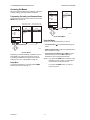
MOUNTING
This section describes the mounting procedures for the
controller and temperature sensor(s).
Controller Mounting
IMPORTANT
Avoid mounting in areas where acid fumes or
other deteriorating vapors can attack the metal
parts of the controller circuit board, or in areas
where escaping gas or other explosive vapors
are present.
IMPORTANT
The controller must be mounted in a position that
allows clearance for wiring, servicing, and
removal.
Use a screwdriver to pry out only the knockouts that you
will use.
If mounting on DIN rail, be sure to remove the knockouts
before mounting. See “Controller Wiring” on page 5 and
Fig. 7 on page 6 for recommended knockout usage and
locations. If you do not use an opened knockout be sure
to cover it.
Mount the controller on any convenient interior location
using the four mounting holes provided on the back of the
enclosure using #6 or #8 screws (screws are not provided
and must be obtained separately). Use controller
dimensions in Fig. 1 on page 2 as a guide.
The controller may be mounted in any orientation.
However, mounting in the orientation shown in Fig. 1
permits proper viewing of the LCD display and use of the
keypad.
NEMA 4 Enclosure Mounting
For models with NEMA 4 enclosures, ensure that
waterproof wire/conduit fittings are used at the knockouts
for all wiring attachments. See Fig. 7 on page 6 for
knockout locations.
IMPORTANT
For NEMA 4 enclosures, be sure to cover and
seal all unused open knockouts.
Temperature Sensor(s) Mounting and
Location
Temperature sensors may be located up to 1,000 feet
(304 m) from the T775A/B/M controller. See Table 3 on
page 10 for calibration guidelines.
The sensors may be mounted on a wall or panel for
sensing space temperature, strapped to a pipe or inserted
in an immersion well (see Fig. 2) for hot or cold water
sensing, or taped to a standard cap or bulb holder for duct
air sensing. To prevent moisture or condensation entering
the sensor through the lead wire holes, mount the sensor
with the lead wires exiting the bottom of the sensor.
NOTES:
1. The included sensor is not designed for very
wet applications. For immersion applications,
an immersion well is used.
2. Heat conductive compound must be used in
immersion wells.
3. See “Temperature Sensors” on page 2 for this
type of installation.
Fig. 2. Sensor inserted in immersion well.
NOTE: Multiple sensors may be parallel-series wired to
sense average temperatures in large spaces.
See Fig. 3 on page 4.
WIRING
All wiring must comply with applicable electrical codes
and ordinances, or as specified on installation wiring
diagrams. Controller wiring is terminated to the screw
terminal blocks located inside the device.
The remainder of this section describes the temperature
sensor wiring and the T775A/B/M controller wiring.
SENSOR
PLACED
IN WELL
IMMERSION
WELL
1/2 NPT
USE HEAT
CONDUCTIVE
COMPOUND
M24470

T775A/B/M SERIES 2000 CONTROLLER WIRING
62-0254–03 4
Wiring Connections Access
To access the wiring connections, remove the two screws
on the left side of the enclosure and gently swing open the
top. Be careful to not stress the ribbon cables that
connect the keypad and LCD display to the controller
circuit board.
Temperature Sensor Wiring
CAUTION
Electrical Shock Hazard.
Can short equipment circuitry.
Make sure that metal tube of sensor does not
short against T terminals in wall-mounted case.
IMPORTANT
Poor wiring practices can cause erratic readings
from the sensor. Avoid the following to ensure
proper operation:
• Do not route the temperature sensor wiring with
building power wiring.
• Do not locate the temperature sensor wiring next
to control contactors.
• Do not locate the temperature sensor wiring near
electrical motors.
• Do not locate the temperature sensor wiring near
welding equipment.
• Make sure good mechanical connections are
made to both the sensor and the controller.
• Do not mount the sensor with the lead wire end
pointing up in an area where condensation can
occur.
If any of the above conditions cannot be
avoided, use shielded cable.
NOTE: Each T775 controller must be wired to its own
sensor(s). However, a benefit of the T775
controller’s accuracy is that there is no more
than a 2°F differential between any two T775
controllers.
Multiple Parallel Sensors
Multiple sensors can be parallel-series wired to sense
average temperatures in large spaces. To maintain
control accuracy, the number of sensors to be parallel-
series wired must be of the n
2
power (for example, 4, 9,
16, etc.). See Fig. 3.
Fig. 3. Parallel-series wiring of sensors.
Temperature Sensor Wire Type and Size
Temperature sensors use standard AWG 18/2 unshielded
wire. For cable runs greater than 25 feet or where
electrical interference may be a problem, shielded cable
is recommended. See Fig. 4.
Refer to “Temperature Sensor Calibration” on page 10 for
wire size selection where cable runs are longer than 25
feet.
Fig. 4. Sensor wiring — showing shielded cable connection to Sensor A.
TO T775 CONNECTIONS (SENSOR A) OR (SENSOR B).
SENSORS
M24471
M24472
SHIELDED
CABLE
SHIELDED
CABLE
SENSOR
SENSOR A AND SENSOR B TERMINAL WIRING IS POLARITY INSENSITIVE.
1
NOTE: SHIELDED CABLE MUST BE
CONNECTED TO AN EARTH
GROUND.
HOWEVER, DO NOT GROUND
SHIELDED CABLE AT SENSOR END.
NOTE: TO MINIMIZE NOISE PICKUP,
MAKE SENSOR CONNECTION FROM
SHIELDED CABLE AS CLOSE AS
POSSIBLE TO SENSOR BODY.
T
T
T
T
SENSOR A
SENSOR B
1

WIRING T775A/B/M SERIES 2000 CONTROLLER
5 62-0254–03
Controller Wiring
WARNING
Electrical Shock Hazard.
Can cause severe injury, death or property
damage.
Disconnect power supply before beginning wiring,
or making wiring connections, to prevent electrical
shock or equipment damage.
CAUTION
Do not use 24 Vac power to power any external
loads if 120 Vac or 240 Vac is used to power
the T775A/B/M controller.
CAUTION
A separate earth ground is required.
Equipment damage can result if the earth ground
is not connected. See Fig. 5 and Table 2 on
page 6.
CAUTION
Equipment Damage Hazard.
Electrostatic discharge can short equipment
circuitry.
Ensure that you are properly grounded before
handling the unit.
Fig. 5. Earth Ground.
IMPORTANT
Poor wiring practices can cause erratic readings
from the sensor. To ensure proper operation,
ensure that good mechanical connections are
made to both the sensor and the controller.
IMPORTANT
When wiring the input power, only one source of
power can be applied to the T775A/B/M control-
ler (24 Vac or 120 Vac or 240 Vac).
See Fig. 7 on page 6 for locating the appropriate power
input, remote sensors input, low voltage, contact closure,
and load output terminals.
Access to the terminals can be gained through standard
conduit knockouts (A through E in Fig. 7 on page 6)
located around the perimeter of the enclosure:
• Knockouts A and B should be used only for sensor and
low-voltage wiring.
• Knockouts C, D, and E can be used to gain access to
the load relay output terminals and 120/240 Vac power
wiring.
Controller Wiring Method
Wire the sensors and outputs, then wire the power
connection.
Each terminal can accommodate the following gauges of
wire:
• Single wire – from 14 AWG to 22 AWG solid or
stranded
• Multiple wires – up to two 22 AWG stranded
For 24, 120, or 240 Vac power connections:
Single wire – from 14 to 18 AWG solid or stranded
Prepare wiring for the terminal blocks, as follows:
1. Strip 1/2 in. (13 mm) insulation from the conductor.
2. Cut a single wire to 3/16 in. (5 mm). Insert the wire
in the required terminal location and tighten the
screw.
3. If two or more wires are being inserted into one ter-
minal location, twist the wires together a minimum
of three turns before inserting them to ensure
proper electrical contact.
4. Cut the twisted end of the wires to 3/16 in. (5 mm)
before inserting them into the terminal and tighten-
ing the screw.
5. Pull on each wire in all terminals to check for good
mechanical connection.
Fig. 6. Attaching two or more wires at terminal blocks.
C
+
W
1
2
M24296
NO HIGH VOLTAGE. CLASS 2 WIRING ONLY.
EARTH GROUND TERMINAL MUST BE CONNECTED
TO CONDUIT CLAMP LOCALLY.
1
2
1/2 (13)
1. STRIP 1/2 IN. (13 MM)
FROM WIRES TO
BE ATTACHED AT
ONE TERMINAL.
2. TWIST WIRES
TOGETHER WITH
PLIERS (A MINIMUM
OF THREE TURNS).
3. CUT TWISTED END OF WIRES
TO 3/16 IN. (5 MM) BEFORE INSERTING
INTO TERMINAL AND TIGHTENING SCREW.
THEN PULL ON EACH WIRE IN ALL
TERMINALS TO CHECK FOR
GOOD MECHANICAL CONNECTION.
M24473

T775A/B/M SERIES 2000 CONTROLLER WIRING APPLICATIONS (EXAMPLES)
62-0254–03 6
Controller Wiring Details
The wiring connection terminals are shown in Fig. 7 and
are described in Table 2.
See Fig. 8 – Fig. 20 beginning on page 6 for typical
T775A/B/M wiring applications.
Fig. 7. T775A/B/M terminal and feature locations.
NOTE: Refer to Table 1 on page 1 for the specific con-
figuration of sensors and outputs supported by
the model you are installing.
NOTE: For NEMA 4 enclosures, use waterproof fittings
for wiring/conduit connections at knockouts.
WIRING APPLICATIONS
(EXAMPLES)
Fig. 8 – 20 illustrate typical controller wiring for various
applications.
Fig. 8. Wiring for two-stage control – 24 Vac input and
24 Vac load.
Table 2. Description of Wiring
Terminal Connections.
Connection Terminal Label Description
Sensors
Sensor A
T T
Temperature Sensor;
polarity insensitive
Sensor B
Outputs
Relay 1
Relay 2
Relay 3
Relay 4
NO
COM
NC
120-240 Vac Relay
Output
Mod 1
+ - (Vdc or mA)
W R B (Series 90)
a
Modulating Output
Mod 2
M24474
C
NO
NC
C
NO
NC
C
NC
NO
C
NC
NO
T
T
T
T
B
R
W
+
–
+
–
B
R
W
+
–
SENSOR A
SENSOR B
MOD 2
MOD 1
KNOCKOUT A
DIGITAL
INPUT
POWER
120/240 VAC
OUTPUT
RELAY 2
KNOCKOUT D
POWER
24 VAC
OUTPUT
RELAY 1
KNOCKOUT C
KNOCKOUT E
SENSORS A AND B USE THE TWO TT CONNECTIONS AND ARE
POLARITY INSENSITIVE.
FOR MOD 1 AND MOD 2 CURRENT (mA) OR VOLTAGE (VDC) OUTPUT,
USE SIGNAL (+) & COMMON (-).
FOR MOD 1 AND MOD 2 SERIES 90 OUTPUT, USE W, R, & B.
A SEPARATE EARTH GROUND IS REQUIRED FOR ANY POWER
SOURCE (24, 120, OR 240 VAC).
1
2
1
2
OUTPUT
RELAY 3
KNOCKOUT B
OUTPUT
RELAY 4
3
3
C
+
120
COM
240
Input
DI + - Digital Input (dry
contact)
24 Vac Power
24V + + 24 Vac Hot
Common C 24 Vac Common
Ground
Earth Ground
b
120 or 240 Vac Power
120 Vac 120 120 Vac Power
Common COM Common
240 Vac 240 240 Vac Power
a
For Series 90 connections, you must insert a 340 Ohm
resistor across terminals R and W. See Fig. 17 on
page 8. The resistor is included with the controller.
b
A separate earth ground is required for all installations
regardless of the power source (24, 120, or 240 Vac).
See Fig. 5 on page 5.
Table 2. Description of Wiring
Terminal Connections. (Continued)
Connection Terminal Label Description
L1
(HOT)
L2
24 VAC
COM
NO
COM
NO
M24475A
LOAD 2
LOAD 1
SENSOR A
C
NO
NC
C
NO
NC
T
T
C
+

WIRING APPLICATIONS (EXAMPLES) T775A/B/M SERIES 2000 CONTROLLER
7 62-0254–03
Fig. 9. Wiring for four-stage control – 24 Vac input
and 24 Vac load.
Fig. 10. Wiring for two-stage control with 120 or 240
Vac (120 Vac input and 120 Vac load shown).
Fig. 11. Wiring for four-stage control with 120 or 240
Vac (120 Vac input and 120 Vac load shown).
Fig. 12. Wiring for floating output (Relay 1 and Relay 2
pair shown).
L1
(HOT)
L2
24 VAC
M24476
A
SENSOR A
C
NO
NC
C
NO
NC
C
NC
NO
C
NC
NO
T
T
COM
LOAD
4
NO
LOAD
3
LOAD
2
LOAD
1
C
+
COM
NO
COM
NO
COM
NO
SENSOR A
C
NO
NC
C
NO
NC
T
T
COM
LOAD 2
LOAD 1
NO
COM
NO
COM
120V
M24477A
1
1
FOR 240 VAC LOAD, CONNECT TO 240 TERMINAL.
C
+
120
COM
240
POWER SUPPLY
L1 (HOT )
L2
SENSOR A
1
FOR 240 VAC LOAD, CONNECT TO 240 TERMINAL.
C
NO
NC
C
NO
NC
C
NC
NO
C
NC
NO
T
T
COM
120V
1
M24478A
LOAD 1
LOAD
3
LOAD
2
COM
NO
LOAD 4
C
+
120
COM
240
COM
NO
C
NO
NC
C
NO
NC
BARCODE
M24479
CLOSE RELAY TO DRIVE DEVICE OPEN. RELAY 1 SHOWN.
(RELAYS 1 AND 3 ARE USED FOR OPEN).
CLOSE RELAY TO DRIVE DEVICE CLOSED. RELAY 2 SHOWN.
(RELAYS 2 AND 4 ARE USED FOR CLOSE).
THE RELAYS MUST BE WIRED IN PAIRS WITH RELAYS 1 AND 2
BEING THE FIRST PAIR, AND RELAYS 3 AND 4 BEING THE SECOND PAIR.
1
2
1
2
120/240 VAC LINE
OPEN
DEVICE
COM
CLOSE
NO
COM
NO
COM

T775A/B/M SERIES 2000 CONTROLLER WIRING APPLICATIONS (EXAMPLES)
62-0254–03 8
Fig. 13. Wiring for ML7984 valve actuator.
Fig. 14. Wiring for Digital Input (dry contact).
Fig. 15. Wiring for mod motor or direct coupled
actuator with 4 to 20 mA control input.
Fig. 16. Wiring for mod motor or direct coupled
actuator with 0 to 10 Vdc control input.
Fig. 17. Wiring for Series 90 Modutrol Motor Control.
Fig. 18. Wiring for changeover relay and
minimum position potentiometer used
with Series 90 Modutrol Motors.
USE SEPARATE TRANSFORMER FOR T775R WHEN USING 24 VAC.
250 OHM RESISTOR
1
2
M24480
MODULATING OUTPUT
TERMINAL (MOD 1)
B
R
W
+
–
B
R
W
+
–
T1 T2 B WR
POWER
OUTPUT
ML7984 ACTUATOR
1
2
M24482
DIGITAL
INPUT
+
–
USE SEPARATE TRANSFORMER FOR T775R WHEN USING 24 VAC.
1
M24481
MODULATING OUTPUT
TERMINAL (MOD 1)
B
R
W
+
–
B
R
W
+
–
POWER
OUTPUT
1
T1 T2
–
+
HONEYWELL MODUTROL MOTOR WITH
4-20 mA MODULATING INPUT
T1 T2 C R
POWER
OUTPUT
USE SEPARATE TRANSFORMER FOR T775R WHEN USING 24 VAC.
1
HONEYWELL MODUTROL MOTOR WITH
VOLTAGE CONTROL INPUT
1
F
M24483
MODULATING OUTPUT
TERMINAL (MOD 1)
B
R
W
+
–
B
R
W
+
–
M24484
TO VERIFY OUTPUT, TEST OPEN CIRCUIT VOLTAGE BETWEEN
THE MOD 1 TERMINALS W AND R.
- MINIMUM (DRIVE CLOSED) SIGNAL LESS THAN 0.17 VDC
- MAXIMUM (DRIVE OPEN) SIGNAL IS GREATER THAN 1.7 VDC
USE SEPARATE TRANSFORMER FOR T775R WHEN USING 24 VAC.
INSERT 340 OHM RESISTOR (INCLUDED) ACROSS TERMINALS R AND W.
1
2
3
MODULATING
OUTPUT
TERMINAL
(MOD 1)
B
R
W
+
–
B
R
W
+
–
T1 T2 B WR
POWER
OUTPUT
HONEYWELL ELECTRONIC
SERIES 90 MODUTROL MOTOR
1
2
3
M24485
USE SEPARATE TRANSFORMER FOR T775R WHEN USING 24 VAC.
A 250 OHM RESISTOR PROVIDES 40% AUTHORITY WHEN
USING A 150 OHM MINIMUM POSITION POTENTIOMETER.
INSERT 340 OHM RESISTOR (INCLUDED) ACROSS TERMINALS R AND W.
1
2
MODULATING OUTPUT
TERMINAL (MOD 1)
B
R
W
+
–
B
R
W
+
–
T1 T2 B WR
POWER
OUTPUT
2
HONEYWELL
ELECTRONIC SERIES 90
MODUTROL MOTOR
1
W R B
MINIMUM POSITION
POTENTIOMETER
(Q209)
SPDT CHANGEOVER
(H205 OR H705)
3
3

WIRING APPLICATIONS (EXAMPLES) T775A/B/M SERIES 2000 CONTROLLER
9 62-0254–03
Fig. 19. Wiring for three Series 90 Modutrol Motors.
Fig. 20. Wiring for unison control of M9184 or M9185 Modutrol IV Motor using one minimum position
potentiometer for all motors.
POWER SUPPLY. PROVIDE DISCONNECT MEANS AND OVERLOAD PROTECTION AS REQUIRED.
USE A 1300 OHM RESISTOR FOR TWO MOTORS, 910 OHM RESISTOR FOR THREE MOTORS.
THE 407EAU RESISTOR KIT, WHICH IS SHIPPED WITH THE M9184 AND M9185 MOTORS,
INCLUDES BOTH RESISTORS.
INSERT 340 OHM RESISTOR (INCLUDED) ACROSS TERMINALS R AND W.
1
2
1
2
M9184 OR M9185
MODUTROL MOTOR
W
R
B
TR
TR
W
R
B
TR
TR
W
R
B
TR
TR
M9184 OR M9185
MODUTROL MOTOR
M9184 OR M9185
MODUTROL MOTOR
L1
(HOT)
L2
M24486
MODULATING OUTPUT
TERMINAL (MOD 1)
B
R
W
+
–
B
R
W
+
–
3
3
POWER SUPPLY. PROVIDE DISCONNECT MEANS AND OVERLOAD PROTECTION AS REQUIRED.
UP TO SIX SIMILAR MOTORS CAN BE CONNECTED IN UNISON.
USE RESISTOR BETWEEN R AND B ON THE MOD 1 TERMINAL: 1300 OHMS FOR TWO MOTORS; 910 OHMS FOR THREE MOTORS (4074EAU KIT).
IF COMMON TRANSFORMER IS USED, ALL MOTORS MUST BE IN PHASE. CONNECT THE SAME TRANSFORMER LEAD TO T1 ON EACH MOTOR,
CONNECT THE OTHER TRANSFORMER LEAD TO T2 ON EACH MOTOR.
USE TEMPERATURE CONTROLLER SUCH AS H205 OR H705, OR T675A FOR CHANGEOVER CONTROL.
AUTHORITY OF MINIMUM POSITION POTENTIOMETER, IF USED, INCREASES WITH THE NUMBER OF MOTORS IN PARALLEL. WITH ONE MOTOR,
50% STROKE; WITH TWO MOTORS, 100% STROKE; WITH THREE MOTORS, 100% STROKE WITH 1/3 OF FULL POTENTIOMETER ROTATION.
REVERSING THE B AND W TERMINALS ON ONE OR MORE MOTORS WILL NOT AFFECT CONTROL PERFORMANCE ON THE OTHER MOTORS.
THE SYSTEM CAN BE CONFIGURED TO HAVE SOME MOTORS BE REVERSE ACTING AND OTHER MOTORS BE DIRECT ACTING.
USE SEPARATE TRANSFORMER FOR T775 WHEN POWERING FROM 24 VAC.
THE SYSTEM IS SHOWN CONNECTED FOR COOLING. FOR HEATING, REVERSE THE W AND B LEADS OF THE MODULATING OUTPUT ON THE
T775 CONTROLLER.
1
1
2
M9184 OR M9185
MODUTROL MOTOR
W
R
B
TR
TR
W
R
B
TR
TR
W
R
B
TR
TR
M9184 OR M9185
MODUTROL MOTOR
M9184 OR M9185
MODUTROL MOTOR
L1 (HOT) L2
W
R
B
MINIMUM
POSITION
POTENTIOMETER
(Q209/S963)
1
2
3
W
B
R
CHANGEOVER
CONTROLLER
6
4
2
2
2
5
7
3
9
6
4
5
7
3
8
9
M24487
MODULATING OUTPUT TERMINAL (MOD 1)
B
R
W
+
–
+
–
B
R
W
+
–
POWER
24 VAC
8
C
+

T775A/B/M SERIES 2000 CONTROLLER CHECKOUT
62-0254–03 10
CHECKOUT
Inspect all wiring connections at the controller terminals,
and verify compliance with the installation wiring
diagrams.
WARNING
Electrical Shock Hazard.
Can cause severe injury, death or property
damage.
Disconnect power supply before beginning wiring
or making wiring connections, to prevent electrical
shock or equipment damage.
If any wiring changes are required, first be sure to remove
power from the controller before starting work. Pay
particular attention to verifying the power connection (24,
120, or 240 Vac).
After the controller is installed and wired, apply power.
Power Loss
The date and time settings are retained for 24 hours after
a power outage. After a power loss of more than 24 hours,
the date and time settings may need to be reentered. All
other settings are stored permanently.
Temperature Sensor Calibration
As wire length increases, resistance increases and thus
the temperature reading increases. If necessary, calibrate
the sensor input by reducing the value by the amount
shown in the Table 3. For example, a wire run with 18
gauge wire of 1,000 feet, requires a calibration offset of
-6.0°F.
IMPORTANT
If the calibration value in the table exceeds the
controller’s calibration limits of +/-10°F (+/-6°C),
you must use a heavier gauge wire.
For example, with a wire run of 1,000 feet you
must use 20 AWG wire or heavier in order to cal-
ibrate for wire loss within the limits of the control-
ler.
See “2.2.2.2. CALIBRATE (the sensor)” on page 18 for
the instructions to enter the calibration value.
Fig. 21 shows how sensor resistance varies with
temperature for a sensor having a positive temperature
coefficient (PTC) of 2.1 Ohms per degree F (3.85 Ohms
per degree C).
Fig. 21. Sensor Resistance vs. Temperature.
Table 3. Temperature Sensor Calibration for
Resistance Loss due to Wire Length.
AWG
Rating mΩ/ft
Temperature Offset in
°F (Foot)
a
a
This is the distance from the controller to the sensor
(already accounts for round trip distance).
200 ft 500 ft 1,000 ft
14 2.5 0.46 1.14 2.28
16 4.0 0.72 1.82 3.64
18 6.4 1.16 2.90 5.82
20 10.2 1.86 4.64 9.28
22 16.1 2.92 7.32 14.64
AWG
Rating mΩ/m
Temperature Offset in
°C (Meter)
a
100 m 200 m 300 m
14 8.3 0.44 0.86 1.30
16 13.2 0.68 1.38 2.06
18 21.0 1.10 2.18 3.28
20 33.5 1.74 3.48 5.22
22 52.8 2.74 5.48 8.22
M24304
TEMPERATURE (DEGREES)
RESISTANCE (OHMS)
1403
1317
1231
1145
1059
973
20 40 60 80 100 120 140 160 180 200 220
0 10 20 30 40 50 60 70 80 90 100
°F
°C
0-20-40
120
110
250
-40 -20 -10-30
1489
887
801
1097 ± 0.08 OHMS
AT 77°F (25°C)
POSITIVE TEMPERATURE COEFFICIENT (PTC) OF 2.1 OHMS PER °F
1
1

INTERFACE OVERVIEW T775A/B/M SERIES 2000 CONTROLLER
11 62-0254–03
INTERFACE OVERVIEW
The T775A/B/M controllers use an LCD panel and
6-button keypad to provide status information and permit
user input of the programming, setup, and scheduling
parameters.
The following figure describes the display areas of the
LCD and the keypad.
Fig. 22. LCD Display - Home Screen And Keypad.
Menu Area – On the home screen, the LCD displays the
configured relays and whether they are active. In
Program, Setup or Schedule mode, the LCD displays the
current menu selection and its order within the menu
hierarchy.
Data Area – On the home screen, the LCD displays the
sensors and outputs status. In Setup or Program mode,
the LCD displays menu choices, parameter selections,
and data values.
Lock Icon – The icon indicates the MENU button is
locked and prevents access to the Setup and Program
menus.
NOTE: Pressing and holding the HOME and MENU but-
tons simultaneously for five seconds locks/
unlocks the MENU button.
6-Button Keypad – The keypad is used to access the
menus and enter values (see “Using the LCD Panel
Interface”).
Using the LCD Panel Interface
The 6-button keypad is used to move through the menus
and enter or change parameter values.
Home Button
Pressing the HOME button at any time exits the current
Programming or Setup display screen and returns to the
home screen as shown in Fig. 22 and Fig. 23.
Menu Button
•Pressing the MENU button always displays the
Program menu. If you are in Setup mode, you exit
setup and return to the Program menu.
• Pressing and holding the MENU button for five
seconds leaves the current screen and displays
the Setup menu.
Left and Right Arrow Buttons (
W and X
)
Use these buttons to move backward (W) and forward (X)
through the Program and Setup menus.
Up and Down Arrow Buttons (
S and T
)
Use these buttons to move your selection up and down
through a menu or list.
• When the desired item is highlighted, you press the X
arrow button to display that item’s content.
• When a value is displayed (e.g. 70°F), the up and
down arrows increase and decrease the value.
NOTE: Once you select an item from a list or enter a
value, pressing the W or X or HOME button
accepts your selection or value and stores it in
the controller’s memory.
Home Screen
In the normal run state, the LCD home screen displays
the current sensed temperatures, the modulating outputs
status, the active status of the output relays, and error and
status codes.
Active relays are indicated by the small black square ()
just below the relay number. Fig. 23 shows the home
screen with relays 1, 2, and 4 energized.
Pressing the W and X buttons from the home screen
cycles through each modulating output that is paired with
the sensor it controls and the active output relays.
Fig. 23. LCD Display - Home Screen Displaying
Sensors, Active Relays, and Mod Outputs.
NOTE: The modulating output home screen and the
relay home screen do not dynamically update
the active relay status, sensor values, and
modulating output percentages. The information
is a snapshot taken when you press the W or X
button to display the screen.
IMPORTANT
After four minutes of inactivity (no buttons
pressed), the LCD display reverts to the home
screen display.
MOD1 40%
MOD2 60%
DI ON
HOME
RELAYS 1 2 3 4
ON
SENSORS
SENSOR A
78
SENSOR B
84
MENU AREA
home menu
F
o
F
o
DATA AREA
LOCK ICON
6 BUTTON KEYPAD
M24488
MOD1 40%
MOD2 60%
DI ON
HOME
RELAYS 1 2 3 4
ON
SENSORS
SENSOR A
78
SENSOR B
84
o
o
F
F
MOD1 40%
MOD2 60%
DI ON
HOME
RELAYS 1 2 3 4
ON
o
F
o
F
REL 1 ON
HEAT
SETPOINT
60
SENSOR A
62
RT 12345 HRS
DI ON
HOME
RELAYS 1 2 3 4
ON
MOD 1 40%
COOL
SETPOINT
74
SENSOR A
62
o
o
F
F
M24489
MOD1 40%
MOD2 60%

T775A/B/M SERIES 2000 CONTROLLER INTERFACE OVERVIEW
62-0254–03 12
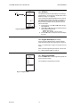
Accessing the Menus
Menus are used for programming, scheduling, viewing the
summary settings, and setup of advanced options.
Programming, Scheduling, and Summary Menus
To access these menus from the home screen, press the
MENU button. See Fig. 24.
Fig. 24. Menus.
Depending on whether scheduling is enabled or not, the
LCD displays one of two menus as shown in Fig. 24.
Scheduling is enabled from the Setup menu’s Output
settings (see “2.3.3.1. USE SCHED” on page 24).
Setup Menu
To access the Setup menu, press and hold the MENU
button for five seconds. See Fig. 25.
Fig. 25. Setup Menu.
Using the Menus
When you are working with the menus, use the:
• Left arrow button (W) to scroll backward through the
menus
• Right arrow button (X) to select the highlighted menu
item and display its content
• Up and Down arrow buttons (S and T) to scroll up
and down through a list of items or to increase or
decrease the value of a displayed parameter
NOTE: If you press the HOME button or there is no key-
pad activity for four minutes, you exit Program
mode and return to the home screen.
If you press the MENU button, you exit and
return to the menu.
MENU
PROGRAM
EXIT
home
menu
OR
MENU DISPLAY WHEN
SCHEDULING IS NOT SET
MENU DISPLAY WHEN
SCHEDULING IS SET
MENU
MOD1 40%
MOD2 60%
DI ON
HOME
RELAYS 1 2 3 4
ON
F
o
F
o
SENSORS
SENSOR A
78
SENSOR B
84
PROGRAM
SCHEDULE
SUMMARY
EXIT
M24490
home
menu
SETUP
MOD1 40%
MOD2 60%
DI ON
HOME
RELAYS 1 2 3 4
ON
FIVE
SECONDS
F
o
F
o
SENSORS
SENSOR A
78
SENSOR B
84
SENSORS
OUTPUTS
EXIT
M24491
Page is loading ...
Page is loading ...
Page is loading ...
Page is loading ...
Page is loading ...
Page is loading ...
Page is loading ...
Page is loading ...
Page is loading ...
Page is loading ...
Page is loading ...
Page is loading ...
Page is loading ...
Page is loading ...
Page is loading ...
Page is loading ...
Page is loading ...
Page is loading ...
Page is loading ...
Page is loading ...
Page is loading ...
Page is loading ...
Page is loading ...
Page is loading ...
-
 1
1
-
 2
2
-
 3
3
-
 4
4
-
 5
5
-
 6
6
-
 7
7
-
 8
8
-
 9
9
-
 10
10
-
 11
11
-
 12
12
-
 13
13
-
 14
14
-
 15
15
-
 16
16
-
 17
17
-
 18
18
-
 19
19
-
 20
20
-
 21
21
-
 22
22
-
 23
23
-
 24
24
-
 25
25
-
 26
26
-
 27
27
-
 28
28
-
 29
29
-
 30
30
-
 31
31
-
 32
32
-
 33
33
-
 34
34
-
 35
35
-
 36
36
-
 37
37
-
 38
38
-
 39
39
-
 40
40
-
 41
41
-
 42
42
-
 43
43
-
 44
44


Honeywell AC-220-7 User manual
- Type
- User manual
Ask a question and I''ll find the answer in the document
Finding information in a document is now easier with AI
Related papers
-
Honeywell T775M2022 Installation Instructions Manual
-
-
-
-
-
-
-
-
-
Other documents
-
 Thermal Transfer AB Series Datasheet
-
Bradford White 47808A User manual
-
TRIANGLE TUBE Optimal Series Temperature Sensor Operating instructions
-
Alan T200WL01 User manual
-
IFM E37411 Installation guide
-
 Ranco ETC-211000-000 Installation guide
-
 Brooks 0254 Operating instructions
-
 Telethings L1 – Smart LoRaWAN Thermostat and Relay Box User manual
-
Daikin 3P419248-1-KA Operating instructions
-
Trane Master Scheduler Owner's manual


