Page is loading ...
®
© 2000 by Motorola, Inc.
8000 W. Sunrise Blvd., Ft. Lauderdale, FL 33322
Printed in U. S. A. 9/00. All Rights Reserved.
Instruction Manual
68P81110C10-O
PA/Speaker
Model HSN1006A
American Communication Systems
Discover the Power of Communications
™
TO ORDER – VISIT
http://www.ameradio.com

PA/Speaker Instruction Manual
ii
6881110C10-O September, 2000
Table of Contents
Description . . . . . . . . . . . . . . . . . . . . . . . . . . . . . . . . . . . . . . . . . . . . . . . . . . . . . . . . . . . . 1
Installation. . . . . . . . . . . . . . . . . . . . . . . . . . . . . . . . . . . . . . . . . . . . . . . . . . . . . . . . . . . . . 1
Adjustment . . . . . . . . . . . . . . . . . . . . . . . . . . . . . . . . . . . . . . . . . . . . . . . . . . . . . . . . . . . . 2
HSN1006A Speaker, Housing Kit, and Parts List. . . . . . . . . . . . . . . . . . . . . . . . . . . . . . 3
NTN9277A Speaker Amplifier Board and Parts List . . . . . . . . . . . . . . . . . . . . . . . . . . . 4
Model HSN1006A PA/Speaker NTN9277A Speaker Board Detail,
Schematic Diagram and Specifications . . . . . . . . . . . . . . . . . . . . . . . . . . . . . . . . . . . . . 5

September, 2000 6881110C10-O
1
Speaker/Amplifier
Model HSN1006A
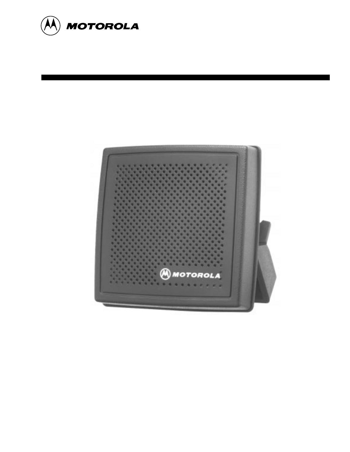
1. Description
1.1 The speaker/ampliÞer consists of a 6-watt
integrated circuit ampliÞer and a 2.0 ohm speaker,
enclosed in a rugged, weather -resistant housing.
The housing is designed to be mounted either
inside or outside (Please see the Window
Mounting Bracket Detail, Figure 1) of a schoolbus,
truck, emergency van, or other similar vehicle.
1.2 The speaker/ampliÞer is used in options for
Motorola XTVA, Vehicular Adapters, and other
similar products.
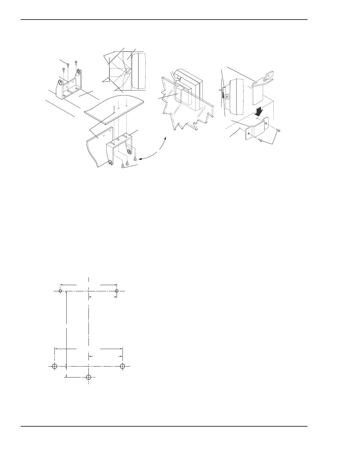
1.3 The speaker/ampliÞer includes a trunnion
bracket, hanger bracket, and wall mount bracket.
These brackets enable the speaker to be mounted
in a variety of different ways. Refer to Figure 1.
The trunnion bracket provides a large variety of
permanent mountings (dashboard and accessible
Þrewall areas) for the speaker, while permitting it
to be tilted or angled for best results.
The hanger bracket (already attached to the
speaker) by itself permits temporary mounting on
projections, such as automobile windows. In this
case, the speaker must be removed from its
trunnion bracket by loosening the two wing
screws.
The wall mount bracket can be used for permanent
mountings if the trunnion bracket is too large to Þt
in inaccessible areas. In this case, remove the
trunnion bracket and attach the speaker to the wall
mount bracket using the hanger bracket. Security
screws are included for optional use in place of
wing screws.
2. Installation
2.1 These tools are required for installation:
¥ Center punch
¥ Hammer
¥ Drill, 1/4" Chuck
¥ #22 Twist Drill (0.157") for self-tapping screws
¥ #38 Twist Drill (0.101") for self-tapping screws
¥ Nut Driver, 1/4"
¥ Nut Driver, 5/16"
2.2 Trunnion Bracket Installation Procedure (Refer to
Figure 1.)
Step 1. Remove the trunnion bracket by loosening the
two wing screws.
Step 2. Remove the three paper retainers and screws
from the trunnion bracket.
Step 3. Remove the wall mount bracket from its taped
position on the hanger bracket, and retain for
future use.
Step 4. Using the trunnion bracket as a template,
mark the location of the three desired
mounting holes.
Step 5. Centerpunch and drill a 0.157" diameter hole
at each location.
Step 6. Mount the trunnion bracket using the
supplied screws.
Step 7. Remount the speaker into the trunnion
bracket and retighten the two wing screws.
2.3 Wall Mount Bracket Installation Procedure (Refer
to Figure 1.)
Step 1. Remove the wall mount bracket from its taped
position on the hanger bracket.
Step 2. Remove the trunnion bracket and trunnion
wing screws, and retain for future use.
Step 3. Remove the two paper retainers and screws
from the wall mount bracket.
Step 4. Determine the location for the installation.
Step 5. Using the bracket as a template, mark the
location for the screws.
Step 6. Centerpunch and drill a 0.101" diameter hole
at both locations.
Step 7. Mount the wall mount bracket to the surface
with the supplied screws.
2
6881110C10-O September, 2000
Speaker/Amplifier PA/Speaker Instruction Manual
Step 8. Firmly seat the hanger bracket (attached to the
speaker) in the wall mount bracket.
2.4 Dual Trunnion and Wall Mount Installation
In some installations, such as in schoolbuses,
where the speaker may be subject to excessive
strain or abuse, it may be desirable to use both the
trunnion mounting bracket and the wall mounting
bracket. In this case, follow the procedures in both
2.2 and 2.3, but use the dimensions in Figure 2 to
locate the hole centers.
NOTE
: Do not use Figure 2 as a template.
2.5 Electrical Connections
Install the Vehicular Adapter, or mobile radio,
following the preinstallation and installation
procedures described in the basic Vehicular
Adapter, or mobile radio manual. Use the
Interconnect Cable to install the PA /Speaker to the
Vehicular Adapter or mobile radio.
3. Adjustment
General Procedure
See the Vehicle Adapter, or mobile radio installation
manual for product-speciÞc procedure.
Step 1. Adjust the radio as described in the radio
instruction manual.
Step 2. Setup the conditions required to provide a
signal to the speaker, such as an incoming
received message and set the vehicular
adapter volume level to maximum.
Step 3. Adjust the speaker/ampliÞer volume control
(on the speaker circuit board) for a convenient
listening level heard clearly throughout the
vehicle. The adjustment can also be used to
lower minimum loudness if the installation
requires it.
Figure 2. Dual Trunnion
and Wall Mount Dimensions
1.92"(48.77mm)
0.96"(24.38mm)
2.31"(58.67mm)
1.155"(29.34mm)
2.56"(65.02mm)
0.375"(9.53mm)
Trunnion Bracket
Wall Mounting Bracket
MAEPF-26871-O
Figure 1. Physical Installation Details
0.101’’ (2.56mm)
Diameter
6-20 x 1/2’’
Self-Tapping
Screw
Wall Mounting
Bracket Detail
Wall Mounting
Bracket
NOTE:
The rear cover of the speaker and the
circuit board must be temporarily
removed to mount the hanger bracket.
Hanger
Bracket
Hanger
Bracket
Vehicle
Window
Window Mounting
Detail
Trunnion Bracket
Mounting Detail
Dashboard
Firewall
Trunnion Bracket
To
Firewall
Mounting
or
Dashboard
Firewall
10-16 x 5/8’’
Self-Tapping
Screw
0.157’’ (3.99mm)
Diameter
Trunnion
Bracket
10-16 x 5/8’’
Self-Tapping
Screw
Console or Floor
MAEPF-26870-O
September, 2000 6881110C10-O
3
PA/Speaker Instruction Manual Speaker/Amplifier
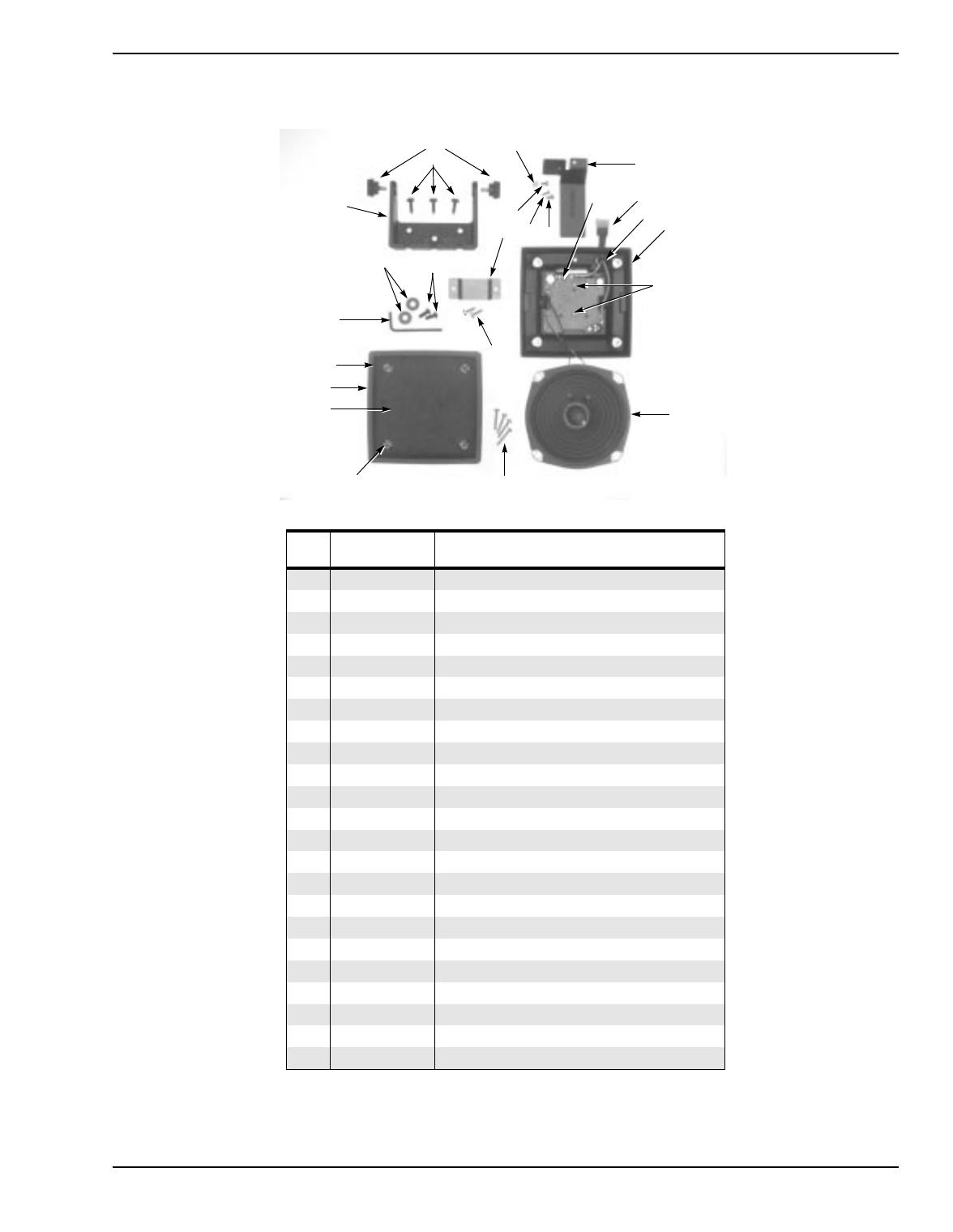
4. HSN1006A Speaker, Housing Kit, and Parts List
Parts List
Item
No.
Motorola
Part Number Description
1
1584981B08 HOUSING ASSMBLY, rear; includes: ref items
2 0780200E06 BRACKET, trunnion
3 0384244C01 SCREW, wing: 10-32 x 3/8"; 2 used
4 0200131435 NUT, hex; 4-40 x 1/4 x 3/32"
5 0784707L02 BRACKET, hanger
6 0300001943 SCREW, machine; 4-40 x 5/16"
7 0300003360 SCREW, tapping; 6-20 x 1/2"; 2 used
8 0784708L01 BRACKET, wall mount
9 0300002941 SCREW, machine, 6-32 x 1/4"; 2 used
10 1382671M04 BEZEL, speaker front
11 0300140001 SCREW, machine; 6-32 x 13/16"; 4 used
12 3584709L01 GRILLE, cloth
13 0480299R01 RING, retainer; 4 used
14 1584954L01 HOUSING, plug; 6-contact
15 4200850861 RETAINER, cable
16 0300139803 SCREW, tapping; 4-20 x 1/4"; 2 used
17 5084561B03 SPEAKER, dynamic; 5"
18 0300136756 SCREW, tapping; 10-16 x 5/8"; 3 used
19 3280000S01 GASKET, speaker
20 0384349K02 SCREW, trunnion security; 2 used
21 0400139941 WASHER, flat; 2 used
22 6684352K01 TOOL, installation
23 1484602K01 INSULATOR
Note:
For optimum performance, diodes, transistors, and integrated circuits must be
ordered by Motorola part numbers.
16
1
2
3
5
8
4
6
7
10
11
12
13
14
15
17
18
9
9
23
20
21
22
19

4
6881110C10-O September, 2000
Speaker/Amplifier PA/Speaker Instruction Manual
5. NTN9277A Speaker Amplifier Board and Parts List
Parts List
Reference
Symbol
Motorola Part
Number
Description
capacitor, fixed: ±5%; 50V;
unless otherwise stated
C1 2380090M06 10uF; 16V
C2 2380090M25 100uF; 25V
C3 2113741B61 .047uF
C4 2380090M32 220uF; 35V
C5 2113741B69 0.1uF
C6 2160521G37 0.1uF
C7 2113743A23 0.22uF
C8 2113741A45 .01uF
C9 2113740A63 220pF
C10 2113740B73 1000pF
C12 2113741A45 .01uF
C14, C15 2113740A63 220pF
resistor, fixed:
Ω
±5%; 1/8 w;
unless otherwise stated
R1
0611077A82 2.2k
R2 1884944C04 500
R3 0611077A42 47
R4 0611077A58 220
R5 0611077A10 2.2
R6 0662057C03 1
R7 0611077A68 560
module:
U1
5180065C03
plug:
P1 (not on board)
6-pin connector; includes:
1584954L01 HOUSING, connector
2984706E05 TERMINAL, pin; 5 used
2984706E01 TERMINAL, pin; 1 used
3000824273 CONDUCTOR, shielded
3700135566 TUBING, heat-shrink
September, 2000 6881110C10-O
5
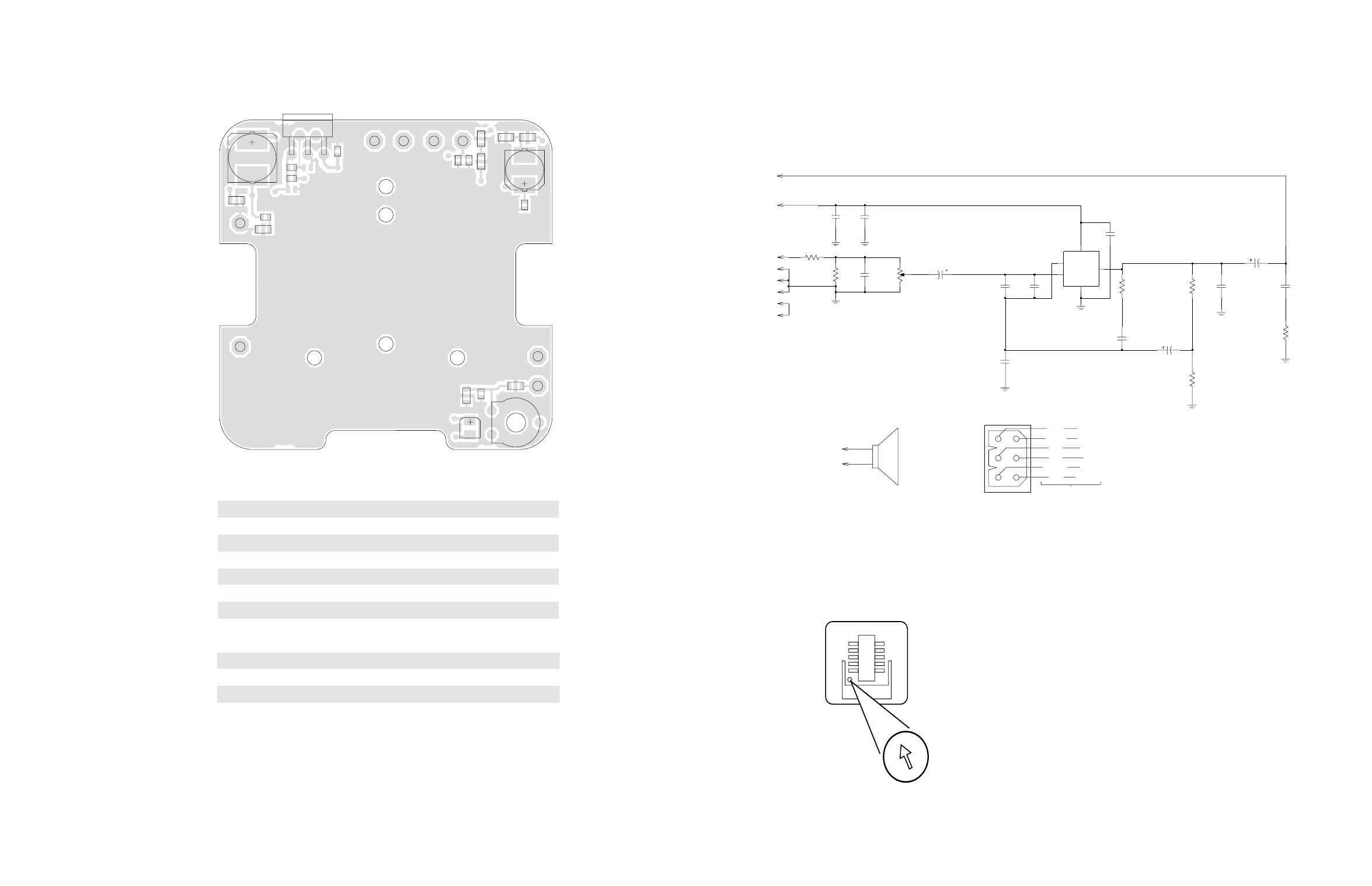
NTN9277A Speaker Board Detail
Speaker/Amplifier Specifications
Speaker/Amplifier Model Complement
NTN9277A Speaker Board Schematic
Function
The speaker/ampliÞer consists of a 6-watt integrated circuit ampliÞer and a 2.0 ohm speaker mounted in a rugged weather
resistant housing.
Rated Voltage:
+13.8 Vdc; negative ground
Audio Input: 2400 ohms with adjustable input level
Input sensitivity: 0.5 volt input for full output
Audio output to speaker: 6 watts; less than 10% distortion @ rated voltage
Frequency response: +1, -3 dB; 300-3000 Hz
Speaker: 5" permanent magnet; 2 ohms
Battery drain: Standby: less than 0.1 amp; Full output: 0.75 amp
NTN9277A Speaker/amplifier board
HSN1006A Speaker and cable
HKN6455A Interconnect cable
A+
AUD_IN
AUD_OUT
VIEWED FROM TOP SIDE
BLK_WHT
C1
C2
C3
C4
C5
C6
C7
C8
C9
C10
C12
C14
C15
GND
R1
1
2
3
R2
R3
R4R5
R6
R7
SHEILD
SPKR
SPKR_BLK_WHT
5
4
3
1
2
U1
MAEPF-26869-O
1
R6
220uF
C5
0.1uF
1000pF
C4
C10
R5
C15
220pF
R4
2.2
100uF
220
C3
.047uF
C2
47
R3
0.22uF
C6
0.1uF
C7
C9
220pF
C14
220pF
C8
.01uF
C1
10uF
500
R2
1
3
3
1
6
5
4
2
2
C12
.01uF
560
R7
2.2K
R1
3
GND
2
INV
1
NINV
4
OUT
5
SUP_VOLT
BLK_WHT
TDA2003
U1
SPKR
SPKR_BLK_WHT
GND
AUD_OUT
AUD_IN
SHEILD
BLK-WHT
BLK
LS1
2 OHM
A+
BLUE
SHIELD
BLK
RED
BLK/WHT
WHT
AUD IN
SHIELD
GND
A+
SPKR
AUD OUT
P1 CONNECTOR
SHORT CABLE
PCB
EDGE
CONNECTIONS
SPKR
63B81078C99-O
ADJUST SPEAKER
When the speaker is installed to XTVA (NLD7654),
it is recommended that the loudness adjustment be
set as depicted above for best receive audio clarity.
MAEPF-27114-O
Model HSN1006A PA/Speaker
NTN9277A Speaker Board Detail, Schematic Diagram
and Specifications


68P81110C10-O
PA/Speaker
Model HSN1006A
68P81110C10-O
A
, Motorola, and XTVA are trademarks of Motorola, Inc.
/