Page is loading ...

1
VRS 750
Vehicular Repeater System
Detailed Service Manual

2
Foreword
The information contained in this manual relates to the VRS750 Vehicular Repeater System, unless
otherwise specified. This manual provides sufficient information to enable service shop personnel to
troubleshoot and repair the VRS750 to the component level.
Safety Information
Before operating the VRS750, please read the “User Safety, Training, and General Information” section in
the front of this manual.
Manual Revisions
Changes which occur after this manual is printed are described in “FMRs.” These FMRs provide complete
information on changes, including pertinent parts list data.
Computer Software Copyrights
The Motorola products described in this manual may include copyrighted Motorola computer programs
stored in semiconductor memories or other media. Laws in the United States and other countries preserve
for Motorola certain exclusive rights for copyrighted computer programs, including, but not limited to,
the exclusive right to copy or reproduce in any form the copyrighted computer program. Accordingly, any
copyrighted Motorola computer programs contained in the Motorola products described in this manual
may not be copied, reproduced, modified, reverse-engineered, or distributed in any manner without the
express written permission of Motorola. Furthermore, the purchase of Motorola products shall not be
deemed to grant either directly or by implication, estoppel, or otherwise, any license under the
copyrights, patents or patent applications of Motorola, except for the normal non-exclusive license to use
that arises by operation of law in the sale of a product.

i
Table of Contents
➠
Foreword . . . . . . . . . . . . . . . . . . . . . . . . . . . . . . . . . . . . . . . . . . . . . . . . . . inside front cover
User Safety, Training, and General Information . . . . . . . . . . . . . . . . . . . . . . . . . . . . . . . iii
Safe Handling of CMOS Integrated-Circuit Devices . . . . . . . . . . . . . . . . . . . . . . . . . . . . . vi
Model Chart for the VRS750 . . . . . . . . . . . . . . . . . . . . . . . . . . . . . . . . . . . . . . . . . . . . . . . vii
VHF VRS750 Performance Specifications . . . . . . . . . . . . . . . . . . . . . . . . . . . . . . . . . . . . viii
UHF VRS750 Performance Specifications . . . . . . . . . . . . . . . . . . . . . . . . . . . . . . . . . . . . viii
Glossary of Terms. . . . . . . . . . . . . . . . . . . . . . . . . . . . . . . . . . . . . . . . . . . . . . . . . . . . . . . . . ix
List of Abbreviations and Acronyms . . . . . . . . . . . . . . . . . . . . . . . . . . . . . . . . . . . . . . . . . .x
1 - Introduction . . . . . . . . . . . . . . . . . . . . . . . . . . . . . . . . . . . . . . . . . . . . . . . . . . . . . . . . . . .1
Description . . . . . . . . . . . . . . . . . . . . . . . . . . . . . . . . . . . . . . . . . . . . . . . . . . . . . . . . . . . . . . . . . . . 1
Ordering Information . . . . . . . . . . . . . . . . . . . . . . . . . . . . . . . . . . . . . . . . . . . . . . . . . . . . . . . . . . . 2
VRS Features . . . . . . . . . . . . . . . . . . . . . . . . . . . . . . . . . . . . . . . . . . . . . . . . . . . . . . . . . . . . . . . . . . 3
Mutually-Exclusive Features . . . . . . . . . . . . . . . . . . . . . . . . . . . . . . . . . . . . . . . . . . . . . . . . . . . . . . 3
2 - Installation . . . . . . . . . . . . . . . . . . . . . . . . . . . . . . . . . . . . . . . . . . . . . . . . . . . . . . . . . . . . 5
VRS Installation . . . . . . . . . . . . . . . . . . . . . . . . . . . . . . . . . . . . . . . . . . . . . . . . . . . . . . . . . . . . . . . . 5
Installation of the Mounting Trunnion, HLN6855 . . . . . . . . . . . . . . . . . . . . . . . . . . . . . . . . . . . . 6
VRS Antenna Installation . . . . . . . . . . . . . . . . . . . . . . . . . . . . . . . . . . . . . . . . . . . . . . . . . . . . . . . . 7
VRS750 Programming . . . . . . . . . . . . . . . . . . . . . . . . . . . . . . . . . . . . . . . . . . . . . . . . . . . . . . . . . . . 7
3 - VRS Operation . . . . . . . . . . . . . . . . . . . . . . . . . . . . . . . . . . . . . . . . . . . . . . . . . . . . . . . . . 19
General . . . . . . . . . . . . . . . . . . . . . . . . . . . . . . . . . . . . . . . . . . . . . . . . . . . . . . . . . . . . . . . . . . . . . 19
Control Unit . . . . . . . . . . . . . . . . . . . . . . . . . . . . . . . . . . . . . . . . . . . . . . . . . . . . . . . . . . . . . . . . . 19
Vehicle Interface Ports. . . . . . . . . . . . . . . . . . . . . . . . . . . . . . . . . . . . . . . . . . . . . . . . . . . . . . . . . . 20
VRS Access . . . . . . . . . . . . . . . . . . . . . . . . . . . . . . . . . . . . . . . . . . . . . . . . . . . . . . . . . . . . . . . . . . . 20
In-Car Monitor . . . . . . . . . . . . . . . . . . . . . . . . . . . . . . . . . . . . . . . . . . . . . . . . . . . . . . . . . . . . . . . 20
Mobile Audio Repeat . . . . . . . . . . . . . . . . . . . . . . . . . . . . . . . . . . . . . . . . . . . . . . . . . . . . . . . . . . . 21
4 - Operation of VRS Options . . . . . . . . . . . . . . . . . . . . . . . . . . . . . . . . . . . . . . . . . . . . . . .23
Base Repeater . . . . . . . . . . . . . . . . . . . . . . . . . . . . . . . . . . . . . . . . . . . . . . . . . . . . . . . . . . . . . . . . . 23
Mobile Detector. . . . . . . . . . . . . . . . . . . . . . . . . . . . . . . . . . . . . . . . . . . . . . . . . . . . . . . . . . . . . . . 23
VRS Transmit PL Generator. . . . . . . . . . . . . . . . . . . . . . . . . . . . . . . . . . . . . . . . . . . . . . . . . . . . . . 23
A
, Private Line, and Motorola are registered trademarks of Motorola Inc.
Systems 9000, ASTRO, Spectra, Call Alert, Private Conversation, Single Tone,
Digital Private-Line, and Slimnet are trademarks of Motorola Inc.
Torx is a trademark of Camcar Div. of Textron, Inc.
© 2001, 2002 by Motorola Inc.
Commercial, Government and Industrial Solutions Sector
8000 W. Sunrise Blvd., Ft. Lauderdale, FL 33322
Printed in U.S.A. 1/02. All Rights Reserved.
68P81094C84-O
Detailed Service Manual

ii
ii
VRS Mode Steering . . . . . . . . . . . . . . . . . . . . . . . . . . . . . . . . . . . . . . . . . . . . . . . . . . . . . . . . . . . . 23
Time-Out Timer. . . . . . . . . . . . . . . . . . . . . . . . . . . . . . . . . . . . . . . . . . . . . . . . . . . . . . . . . . . . . . . 26
VRS Single Tone. . . . . . . . . . . . . . . . . . . . . . . . . . . . . . . . . . . . . . . . . . . . . . . . . . . . . . . . . . . . . . . 26
VRS Mobile-TX Acknowledgment Tones (Conventional Only) . . . . . . . . . . . . . . . . . . . . . . . . . . 27
Flashing Display . . . . . . . . . . . . . . . . . . . . . . . . . . . . . . . . . . . . . . . . . . . . . . . . . . . . . . . . . . . . . . 27
Repeater PPI. . . . . . . . . . . . . . . . . . . . . . . . . . . . . . . . . . . . . . . . . . . . . . . . . . . . . . . . . . . . . . . . . . 27
Quick-Key . . . . . . . . . . . . . . . . . . . . . . . . . . . . . . . . . . . . . . . . . . . . . . . . . . . . . . . . . . . . . . . . . . . 27
5 - Detailed VRS Operation . . . . . . . . . . . . . . . . . . . . . . . . . . . . . . . . . . . . . . . . . . . . . . . . . 29
Multi-VRS Operation . . . . . . . . . . . . . . . . . . . . . . . . . . . . . . . . . . . . . . . . . . . . . . . . . . . . . . . . . . . 29
Rptr PPI—Portable Priority Interrupt . . . . . . . . . . . . . . . . . . . . . . . . . . . . . . . . . . . . . . . . . . . . . . 34
TX PL Self-Clearing . . . . . . . . . . . . . . . . . . . . . . . . . . . . . . . . . . . . . . . . . . . . . . . . . . . . . . . . . . . . 36
ICM Functions. . . . . . . . . . . . . . . . . . . . . . . . . . . . . . . . . . . . . . . . . . . . . . . . . . . . . . . . . . . . . . . . 37
Acknowledgment Tones . . . . . . . . . . . . . . . . . . . . . . . . . . . . . . . . . . . . . . . . . . . . . . . . . . . . . . . . 38
Non-Priority VRS Rules . . . . . . . . . . . . . . . . . . . . . . . . . . . . . . . . . . . . . . . . . . . . . . . . . . . . . . . . . 40
Emergency . . . . . . . . . . . . . . . . . . . . . . . . . . . . . . . . . . . . . . . . . . . . . . . . . . . . . . . . . . . . . . . . . . . 41
6 - Hardware Detailed Theory of Operation. . . . . . . . . . . . . . . . . . . . . . . . . . . . . . . . . . . 43
Transceiver. . . . . . . . . . . . . . . . . . . . . . . . . . . . . . . . . . . . . . . . . . . . . . . . . . . . . . . . . . . . . . . . . . . 43
Interface Board . . . . . . . . . . . . . . . . . . . . . . . . . . . . . . . . . . . . . . . . . . . . . . . . . . . . . . . . . . . . . . . 43
Power Regulation. . . . . . . . . . . . . . . . . . . . . . . . . . . . . . . . . . . . . . . . . . . . . . . . . . . . . . . . . . . . . . 43
Bus Translation Circuitry . . . . . . . . . . . . . . . . . . . . . . . . . . . . . . . . . . . . . . . . . . . . . . . . . . . . . . . 43
Audio Routing Circuitry . . . . . . . . . . . . . . . . . . . . . . . . . . . . . . . . . . . . . . . . . . . . . . . . . . . . . . . . 44
Single Tone Encoder . . . . . . . . . . . . . . . . . . . . . . . . . . . . . . . . . . . . . . . . . . . . . . . . . . . . . . . . . . . 45
Single Tone Decoder . . . . . . . . . . . . . . . . . . . . . . . . . . . . . . . . . . . . . . . . . . . . . . . . . . . . . . . . . . . 45
Boot Control Circuitry . . . . . . . . . . . . . . . . . . . . . . . . . . . . . . . . . . . . . . . . . . . . . . . . . . . . . . . . . 45
Program Sense . . . . . . . . . . . . . . . . . . . . . . . . . . . . . . . . . . . . . . . . . . . . . . . . . . . . . . . . . . . . . . . . 46
Mode Configuration . . . . . . . . . . . . . . . . . . . . . . . . . . . . . . . . . . . . . . . . . . . . . . . . . . . . . . . . . . . 46
7 - Maintenance and Troubleshooting . . . . . . . . . . . . . . . . . . . . . . . . . . . . . . . . . . . . . . . 49
Troubleshooting Procedures . . . . . . . . . . . . . . . . . . . . . . . . . . . . . . . . . . . . . . . . . . . . . . . . . . . . . 49
Disassembly and Reassembly Procedures . . . . . . . . . . . . . . . . . . . . . . . . . . . . . . . . . . . . . . . . . . . 51
VRS Transceiver . . . . . . . . . . . . . . . . . . . . . . . . . . . . . . . . . . . . . . . . . . . . . . . . . . . . . . . . . . . . . . . 56
VRS Tuning and Alignment . . . . . . . . . . . . . . . . . . . . . . . . . . . . . . . . . . . . . . . . . . . . . . . . . . . . . 56
8 - Troubleshooting Charts. . . . . . . . . . . . . . . . . . . . . . . . . . . . . . . . . . . . . . . . . . . . . . . . . 67
Introduction to this Section . . . . . . . . . . . . . . . . . . . . . . . . . . . . . . . . . . . . . . . . . . . . . . . . . . . . . 67
List of Troubleshooting Charts . . . . . . . . . . . . . . . . . . . . . . . . . . . . . . . . . . . . . . . . . . . . . . . . . . . 67
9 - Diagrams and Parts Lists . . . . . . . . . . . . . . . . . . . . . . . . . . . . . . . . . . . . . . . . . . . . . . . . 81
Introduction to this Section . . . . . . . . . . . . . . . . . . . . . . . . . . . . . . . . . . . . . . . . . . . . . . . . . . . . . 81
List of Diagrams and Parts Lists. . . . . . . . . . . . . . . . . . . . . . . . . . . . . . . . . . . . . . . . . . . . . . . . . . . 81
Replacement Parts Ordering . . . . . . . . . . . . . . . . . . . . . . . . . . . . . . . . . . inside back cover

iii
User Safety, Training, and General Information
READ THIS IMPORTANT INFORMATION ON SAFE AND EFFICIENT OPERATION BEFORE INSTALL-
ING AND USING YOUR MOTOROLA MOBILE TWO-WAY RADIO IN A VEHICLE OR AS A CONTROL
STATION.
Compliance with RF Energy Exposure Standards
Your Motorola two-way radio is designed and tested to comply with a number of national and
international standards and guidelines (listed below) regarding human exposure to radio frequency
electromagnetic energy.
This radio complies with the IEEE (FCC) and ICNIRP exposure limits at duty
cycles of up to 50% talk-50% listen and should be used for occupational use only.
In terms of
measuring RF energy for compliance with the FCC exposure guidelines, your radio radiates measurable RF
energy only while it is transmitting (during talking), not when it is receiving (listening) or in standby
mode.
Your Motorola two-way radio complies with the following RF energy exposure standards and guidelines:
•
United States Federal Communications Commission, Code of Federal Regulations; 47CFR part 2 sub-
part J
•
American National Standards Institute (ANSI) / Institute of Electrical and Electronic Engineers (IEEE)
C95. 1-1992
•
Institute of Electrical and Electronic Engineers (IEEE) C95.1-1999 Edition
•
International Commission on Non-Ionizing Radiation Protection (ICNIRP) 1998
•
Ministry of Health (Canada) Safety Code 6. Limits of Human Exposure to Radiofrequency
Electromagnetic Fields in the Frequency Range from 3 kHz to 300 GHz, 1999
•
Australian Communications Authority Radiocommunications (Electromagnetic Radiation - Human
Exposure) Standard 1999 (applicable to wireless phones only)
Operational Instructions and Training Guidelines
To ensure optimal performance and compliance with the RF energy exposure limits in the above
standards and guidelines, users should transmit no more than 50% of the time and always adhere
to the following procedures:
Transmit and Receive
•
To transmit (talk), push the Push-To-Talk (PTT) button; to receive, release the PTT button.
•
Transmit only when people outside the vehicle are at least the minimum lateral distance away,
as shown in Table 1, from a properly installed, externally-mounted antenna.
Table 1 lists the minimum lateral distance for bystanders in an uncontrolled environment from the
transmitting antenna at several different ranges of rated radio power for mobile radios installed in a
vehicle.

iv
iv
Mobile Antennas
•
Install antennas at the center of the roof or the center of the trunk deck. These mobile antenna
installation guidelines are limited to metal body vehicles.
•
The antenna installation must additionally be in accordance with:
a. The requirements of the antenna manufacturer/supplier
b. Instructions in the Radio Installation Manual
•
Use only Motorola approved supplied antenna or Motorola approved replacement antenna.
Unauthorized antennas, modifications, or attachments could damage the radio and may violate FCC
regulations.
Fixed Site Antennas
If mobile radio equipment is installed at a fixed location and operated as a control station or as a fixed
unit, the antenna installation must comply with the following requirements in order to ensure optimal
performance and compliance with the RF energy exposure limits in the above standards and guidelines.
•
The antenna should be mounted outside the building on the roof or a tower if at all possible.
•
As with all fixed site antenna installations, it is the responsibility of the licensee to manage the site in
accordance with applicable regulatory requirements and may require additional compliance actions
such as site survey measurements, signage, and site access restrictions in order to insure that
exposure limits are not exceeded.
Electromagnetic Interference/Compatibility
NOTE:
Nearly every electronic device is susceptible to electromagnetic interference (EMI) if
inadequately shielded, designed or otherwise configured for electromagnetic
compatibility. It may be necessary to conduct compatibility testing to determine if any
electronic equipment used in or around vehicles or near fixed antenna sites is sensitive to
external RF energy and if any procedures need to be followed to eliminate or mitigate the
potential for interaction between the radio transmitter and the equipment or device.
Facilities
To avoid electromagnetic interference and/or compatibility conflicts,
turn off your radio in any facility
where posted notices instruct you to do so
.
Hospitals or health care facilities may be using equipment
that is sensitive to external RF energy.
Table 1. Rated Power and Lateral Distance
Rated Power of Vehicle-Installed
Mobile Two-Way Radio
Minimum Lateral Distance from
Transmitting Antenna
Less than 7 watts 8 inches (20 centimeters)
7 to 15 watts 1 foot (30 centimeters)
16 to 50 watts 2 feet (60 centimeters)
51 to 110 watts 3 feet (90 centimeters)

v
Vehicles
To avoid possible interaction between the radio transmitter and any vehicle electronic control modules,
for example, ABS, engine, or transmission controls, we recommend that the radio be installed by an
experienced installer and that the following precautions be used when installing the radio:
1. Refer to any manufacturers instructions or other technical bulletins or recommendations on radio
installation.
2. Before installing the radio, determine the location of the electronic control modules and their
harnesses in the vehicle.
3. Route all radio wiring, including the antenna transmission line, as far away as possible from the
electronic control units and associated wiring.
Driver Safety
Check the laws and regulations on the use of radios in the area where you drive. Always obey them.
When using your radio while driving, please:
•
Give full attention to driving and to the road.
•
Pull off the road and park before making or answering a call if driving conditions so require.
Operational Warnings
For Vehicles With an Air Bag
Do not place a portable or mobile radio in the area over an air bag or in the air bag deployment area. Air
bags inflate with great force. If a radio is placed in the air bag deployment area and the air bag inflates,
the radio may be propelled with great force and cause serious injury to occupants of the vehicle.
Potentially Explosive Atmospheres
Turn off your radio prior to entering any area with a potentially explosive atmosphere. Sparks in a
potentially explosive atmosphere can cause an explosion or fire resulting in bodily injury or even
death.
The areas with potentially explosive atmospheres referred to above include fueling areas such as below
decks on boats, fuel or chemical transfer or storage facilities, areas where the air contains chemicals or
particles, such as grain, dust or metal powders, and any other area where you would normally be advised
to turn off your vehicle engine. Areas with potentially explosive atmospheres are often but not always
posted.
Blasting Caps and Blasting Areas
To avoid possible interference with blasting operations, turn off your radio when you are near electrical
blasting caps, in a blasting area, or in areas posted: "Turn off two-way radio." Obey all signs and
instructions.
For radios installed in vehicles fuelled by liquefied petroleum gas, refer to the (U.S.) National Fire
Protection Association standard, NFPA 58, for storage, handling, and/ or container information. For a
copy of the LP-gas standard, NFPA 58, contact the National Fire Protection Association, One Battery Park,
Quincy, MA.

vi
vi
Safe Handling of CMOS Integrated-Circuit Devices
Many of the integrated-circuit (IC) devices used in communications equipment are of the CMOS (Complementary
Metal Oxide Semiconductor) type. Because of their high open-circuit impedance, CMOS ICs are vulnerable to damage
from static charges. Everyone involved in handling, shipping, and servicing them must be extremely careful not to
expose them to such damage.
CMOS ICs do have internal protection, but it is effective only against overvoltages in the hundreds of volts, such as
those that could occur during normal operations. Overvoltages from static discharge can be in the thousands of volts.
When a CMOS IC is installed in a system, the circuit elements in the system distribute static charges and load the
CMOS circuits. This decreases the vulnerability of the ICs to static discharge, but improper handling will probably
cause static damage even when the ICs are so installed.
To avoid damaging CMOS ICs, take the following precautions when handling, shipping, and servicing them.
1. Before touching a circuit module, particularly after having moved around in the service area, touch both hands
to a bare-metal, earth-grounded surface. This discharges any static charge you may have accumulated.
NOTE:
Wear a conductive wrist strap (Motorola part number RSX-4015A) to minimize the buildup of
static charges on your person while you are servicing CMOS equipment.
When wearing a conductive wrist strap, be careful near sources of high voltage.
By grounding you thoroughly, the wrist strap also increases the danger of lethal
shock from accidental contact with such a source.
2. Whenever possible, avoid touching any electrically conductive parts of the circuit module with your hands.
3. Check the INSTALLATION and MAINTENANCE sections of this manual and the notes on the schematic to find
out whether or not you can insert or remove circuit modules with power applied to the unit, and act
accordingly.
4. When servicing a circuit module, avoid carpeted areas, dry environments, and the wearing of static-generating
clothing.
5. Be sure that all electrically powered test equipment is grounded. Attach the ground lead from the test
equipment to the circuit module before connecting the test probe. Similarly, disconnect the test probe before
removing the ground lead.
6. When you remove a circuit module from the system, lay It on a sheet of aluminum foil or other conductive
surface connected to ground through 100,000 ohms of resistance.
If the aluminum foil is connected directly to ground, you may get a shock if you
touch it and another electrical circuit at the same time.
7. When soldering, be sure the soldering iron is grounded.
8. Before connecting jumpers, replacing circuit components, or touching CMOS pins (if this becomes necessary
during the replacement of an integrated-circuit device), be sure to discharge any static buildup on your person
(see step 1, above). Because you can have a voltage difference across your body, you should use only one hand if
you must touch the board wiring or any of the pins on the CMOS device.
9. When replacing a CMOS integrated-circuit device, leave the device in its metal rail container or conductive
foam until you are ready to insert it into the pronged circuit module.
10. Connect any low-impedance test equipment, such as a pulse generator, to CMOS device inputs after you have
applied power to the CMOS circuitry. Similarly, disconnect such low-impedance equipment before turning off
the power.
11. Wrap CMOS modules in conductive material when transporting them from one area to another, even within
the same room. Use wrapping material similar to that in which replacement modules are wrapped when they
arrive from the factory. (You can also use aluminum foil.) Never use nonconductive material for packaging these
modules.

vii
Model Chart for the VRS750
MODEL NUMBER
DESCRIPTION
P2080 VRS750 VHF (136-174 MHz)
P2081 VRS750 UHF R1 (403-470 MHz)
P2082 VRS750 UHF R2 (450-512 MHz)
ITEM NUMBER DESCRIPTION
X X X
HHN4044* VRS750 Housing
X X X
HLN6855* VRS750 Mounting Assembly
X X X
PLN7780
†
VRS750 Controller Board
X
X X
HLN6856* XCVR Hardware
X
PMLD4196 VHF Transceiver
X
PMLE4242 UHF R1 Transceiver
X
PMLE4243 UHF R2 Transceiver
X
X X
HKN6153 Cable, Mobile-to-VRS
1 1 1
HKN6154 Cable, Siren-to-VRS
2 2 2
6881094C84 VRS750 Detailed Service Manual
X XX
2884606M01 Mini-UHF crimp connector
X XX
YLN4480 VRS Pushbutton
X XX
HBN5086 Packing Kit
3085031D01 Cable, VRS Programming (accessory)
NTN4056 Adapter, VRS Flash programming (accessory)
NKN6460 y-cable kit for dual controlhead w/vrs (accessory)
TLN5277 DC filter for excessive alternator whine (accessory)
RLN5394 VRS750 Test Box (accessory)
3080384N02 VRS750 ATE Cable (accessory)
1
= With option G334AC. Deletes HKN6153 cable.
2
= One item per 10 units.
*For piece part information, refer to the Exploded View section.
†
For piece part information, refer to the Electrical Parts List section.

viii
viii
VHF VRS750 Performance Specifications
UHF VRS750 Performance Specifications
GENERAL TRANSMITTER RECEIVER
Model
P2080 (136-174 MHz)
†
Number of Channels:
1, T1 = R1
Frequency:
Programmable, Synthesized
Frequency Channel
Channel Spacing:
12.5/20/25 kHz
Operation Temp. Range:
-30°C to +60°C
Primary Power:
13.8 VDC ± 20%,
Negative Ground
DC Current Drain (max):
120 mA Receive
500 mA Transmit @ 275 mW
1.10 A Transmit @ 2 W
Squelch Operation:
Private-Line required for
repeater access
Duty Cycle:
Intermittent per EIA at 275 mW
PPI Sample Time:
16 ms Typical
Singletone Encoder/Decoder:
Nominal 847.5 Hz
FCC Identifiers:
AZ492FT3802 (P2080)
Industry Canada:
RF Power Out:
275 mW to 2 W tunable
Spurious and Harmonic Emissions:
-36 dBm < 1 GHz
-30 dBm > 1 GHz
Frequency Stability:
±2.5 ppm @ 25 kHz
±2.5 ppm @ 12.5 kHz
Modulation Limiting (Max):
±2.5 kHz @ 12.5 kHz
±4.0 kHz @ 20 kHz
±5.0 kHz @ 25 kHz
Audio Response: (from 6 dB/octave
pre-emphasis, 300 to 3000 Hz)
+1, -3 dB
Audio Distortion: 3% Typical @ 1 kHz,
60% maximum deviation
FM Hum and Noise: -40 dB
TX Attack Time: 32 ms Typical
Antenna Impedance: 50 ohms
Antenna Connector: mini-uhf
Intermodulation per EIA: 70 dB
Hum and Noise: -40dBm @ 25 kHz
-35dBm @ 12.5 kHz
Reference Sensitivity (typical):
0.28 µV (-118dBm) at 12 dB SINAD
Conducted Spurious Rejection: 70 dB
Adjacent Channel Selectivity:
60 dB @ 12.5 kHz
70 dB @ 25/30 kHz
Audio Response (0.3-3 kHz): +1 to -3 dB
Audio Distortion: 3% Typical @
Mobile Rated Audio*
Conducted Spurious Emissions:
-57 dBm <1 GHz
-47 dBm > 1 GHz
RX Attack Time: 60 ms Typical
*Typically 5 W in 8 ohms.
†
Consult the product catalog sheets (ECAT Price Pages) for a list of disallowed frequencies.
GENERAL TRANSMITTER RECEIVER
Model P2081 (403-470 MHz)
P2082 (450-512 MHz)
†
Number of Channels: 1, T1 = R1
Frequency: Programmable, Synthesized
Frequency Channel
Channel Spacing: 12.5/20/25 kHz
Operation Temp. Range: -30°C to +60°C
Primary Power: 13.8 VDC ± 20%,
Negative Ground
DC Current Drain (max): 120 mA Receive
700 mA Transmit @ 275 mW
1.20 A Transmit @ 2 W
Squelch Operation: Private-Line required for
repeater access
Duty Cycle: Intermittent per EIA at 275 mW
PPI Sample Time: 16 ms Typical
Singletone Encoder/Decoder:
Nominal 847.5 Hz
FCC Identifiers: AZ492FT4848 (P2081)
AZ492FT4849 (P2082)
Industry Canada:
RF Power Out: 275 mW to 2 W tunable
Spurious and Harmonic Emissions:
-36 dBm < 1 GHz
-30 dBm > 1 GHz
Frequency Stability:
±2.5 ppm @ 25 kHz
±2.5 ppm @ 12.5 kHz
Modulation Limiting (Max):
±2.5 kHz @ 12.5 kHz
±4.0 kHz @ 20 kHz
±5.0 kHz @ 25 kHz
Audio Response: (from 6 dB/octave
pre-emphasis, 300 to 3000 Hz)
+1, -3 dB
Audio Distortion: 3% Typical @ 1 kHz,
60% maximum deviation
FM Hum and Noise: -40 dB
TX Attack Time: 14 ms Typical
Antenna Impedance: 50 ohms
Antenna Connector: mini-uhf
Intermodulation per EIA: 70 dB
Hum and Noise: -40dBm @ 25 kHz
-35dBm @ 12.5 kHz
Reference Sensitivity (typical):
0.28 µV (-118 dBm) at 12 dB SINAD
Conducted Spurious Rejection: 70 dB
Adjacent Channel Selectivity:
60 dB @ 12.5 kHz
70 dB @ 25/30 kHz
Audio Response (0.3-3 kHz): +1 to -3 dB
Audio Distortion: 3% Typical @
Mobile Rated Audio*
Conducted Spurious Emissions:
-57 dBm <1 GHz
-47 dBm > 1 GHz
RX Attack Time: 60 ms Typical
*Typically 5 W in 8 ohms.
†
Consult the product catalog sheets (ECAT Price Pages) for a list of disallowed frequencies.

ix
Glossary of
Terms
The following glossary of terms and definitions help you to understand the
VRS theory of operation.
Countdown A term that describes the incremental step-down function of the counter in
the repeater. Approximately 500 milliseconds of time delay for conventional
modes and 1500 milliseconds for trunked modes separate each successive
delay state.
Delay State The specific condition of the counter. A series of eight delay states prioritize
the repeaters within a common geographical area. Delay state zero has the
least time delay (0 milliseconds); delay state seven has the greatest delay
(approximately 3.5 seconds for conventional modes, and 10.5 seconds for
trunked modes). A unit that is in delay state zero is the priority unit.
Disable The deactivation of the repeater. Press the VRS button on the control head or
switch the VIP input off.
Enable The activation of the repeater. Press the VRS button on the control head or
switch the VIP input on.
Inhibit A condition that occurs when the countdown sequence of the logic circuitry
of the repeater ends, or anytime the repeater stops transmitting.
Non-Priority
Repeater
A repeater in any delay state other than delay state zero. This unit is inactive
and does not repeat until the unit steps down to delay state zero.
PTT The Push-To-Talk button on a portable radio or mobile microphone.
Priority Repeater A repeater with its counter in delay state zero. This unit repeats any signal with
the proper carrier frequency and PL code.
Quick-Key A short press of the portable’s PTT—one that is long enough for the VRS to key
the mobile and access the trunking system, but less than 1 second in duration.
Single Tone Burst When a repeater enables, it transmits a 700-millisecond audible tone. This
tone burst increases the delay counter in all other repeaters within range of the
transmitting vehicle by one delay increment.

x
x
List of
Abbreviations
and Acronyms
B-P Base to Portable
CPS Customer Programming Software
DPL Digital Private Line
HUB Hang Up Box
ICM In Car Monitor
ms Millisecond
PAC Portable Area Coverage
PL Private Line
PPI Portable Priority Interrupt
P-B Portable to Base
RF Radio Frequency
RX Receive
SB Serial Bus
SBEP Serial Bus Expanded Protocol
TOT Time Out Timer
TX Transmit
VIP Vehicle Interface Port
VRS Vehicular Repeater System
VRS-EP Vehicular Repeater System—Expanded Protocol
VRS750 Vehicular Repeater System—Model 750

1
Introduction
1
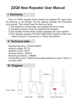
Description The VRS750 Vehicular Repeater System is a mobile radio system
component that provides on-site repeater capability between a
portable radio and a base station (see Figure 1). The VRS gives the
portable user the equivalent range of a mobile radio with the flexibility
of a portable. The VRS is not an ASTRO-capable radio; instead, it is
designed to interface with an ASTRO Spectra
®
mobile radio. It can only
transmit and receive clear analog transmissions.
The VRS receives transmissions on the portable radio’s transmit
frequency with the proper access PL, and passes these portable signals
to the mobile radio. The mobile radio re-transmits the signals to the
base station on the mobile radio’s transmit frequency.
NOTE: These transmissions have the mobile’s ID, not the
portable’s.
Similarly, base station signals received by the mobile radio are sent to
the VRS and re-transmitted to the portable radio. The VRS does not
provide local repeater capability (received portable signals are not
repeated on the portable receive frequency).
The VRS-to-portable and portable-to-VRS communications are limited
to clear analog only. This is a simplex-only interface; the VRS cannot
receive and transmit simultaneously. The base station-to-mobile and
mobile-to-base communications protocol is not limited to analog
only. Rather, this interface is limited by the features and functions of
the ASTRO Spectra and the base.
Figure 1. VRS750 Vehicular Repeater System
SPEAKER
CONTROL HEAD
ASTRO MOBILE
VRS750
HKN6153A
MOBILE
MICROPHONE

2
Ordering
Information
The VRS is a crossband repeater that operates on either UHF or VHF
frequencies. The repeater cannot be operated with a mobile radio
operating in the same band as the VRS unit.
The VRS RF platform is based on a synthesized transceiver. The VRS
supports one channel whose frequency and channel spacing can be
programmed in the field. The VRS remains a simplex repeater and as a
result, the transmit frequency must be set equal to the receive
frequency. The VRS receives its programming information from the
ASTRO Spectra mobile at power-up. The ASTRO Spectra mobile
supports the VRS programming fields via ASTRO Customer
Programming Software (CPS). For more information, refer to “VRS750
Programming,” in Chapter 2, “Installation.”
The VRS is not compatible with ASTRO Spectra mobiles with the
VSELP signaling type.
When integrating a VRS with an ASTRO mobile with a Siren/PA, an
alternate interface cable is needed (HKN6154A). This cable allows the
VRS to be connected to the Siren/PA. For more information, refer to
“Installation,” Chapter 2.
When integrating a VRS with an ASTRO mobile with Dual Control
heads, an alternate interface cable is needed (NKN6460A). This y-cable
allows the VRS to be connected to the ASTRO mobile with two control
heads.
A separate antenna (not included) is necessary for use with the
repeater. Typically, a one-quarter (1/4) wave length antenna
maximizes radiation efficiency when installed at the center of the
vehicle roof. If it is necessary to mount the antenna on the vehicle’s
trunk lid, an appropriate 3 dB gain antenna should be used. See “VRS
Antenna Installation,” in Chapter 2, for details.
A filter for the battery lines (TLN5277B) is available for use with ASTRO
Spectra mobiles. This filter can be used to prevent excessive alternator
whine noise from being heard on the mobile speaker during VRS
operation.
The VRS ships from the factory with the low output power setting at
275 mW and a high output power setting of 2 W. The low output
power setting is the default setting. We recommend the LOW Transmit
Power setting of 275 mW for optimal performance. This output power
provides the VRS with a similar range as the portable when attached
to a mobile antenna. Any deviation from this setting could result in a
loss of communication from the portable to the base.
The Global Tuning Tool (not included) can be used to tune the VRS
output power in the field. For more information refer to “VRS750
Global Tuner,” in Chapter 2.
Contact Customer Resources for information on how to obtain this
Global Tuning Tool.

3
VRS Features The VRS operates with the ASTRO mobile radio and contains the
following integrated features:
• Automatic, multiple-unit, priority-resolution algorithm.
• Portable priority interrupt (PPI) function.
• Conventional/trunked operation.
• Remote switch enable/disable capability for control charger
interface.
• Remote activation of emergency alarm feature.
• In-car monitor operation.
• VRS mobile access tones.
• Mobile radio transmitter steering of up to eight modes via Private-
Line
®
(PL) code transmission from the portable radio.
• TX PL generator.
• Base repeater operation for two-frequency, simplex, fixed-repeater
systems.
• Mobile audio repeat.
• Over-the-air interoperability with VRS-EP units.
All VRS features can be programmed in the field using ASTRO Spectra
mobile CPS. For more information, refer to “VRS750 Programming,”
in Chapter 2.
IMPORTANT NOTE: All ASTRO Spectra VRS systems with the
same VRS RF transmit/receive frequency
need to be CPS programmed identically
to ensure proper operation. Failure to do
so could result in erratic system operation.
The VRS does not have to be installed in the system for
programming—only the mobile radio is programmed. If the VRS is not
connected after programming the mobile system, an error message
“ERR 12/10” will be displayed on the control head.
Mutually-Exclusive
Features
The VRS IS NOT compatible with the following mobile radio features:
• W3 Control Head is not supported with VRS
• Flush-mounted control heads
• VSELP signaling type
• Data—VRS and data are not compatible on the same channel and
cannot be used simultaneously. VRS should never be activated on
a channel that has packet data enabled, and VRS mode steering
channels should not have packet data enabled.
• Scan
• Over-the-Air Rekeying (OTAR) Rekey Request

4
• Message (from the Control Head)—Trunking or Conventional
• Status (from the Control Head)—Trunking or Conventional
• Emergency Call—Trunking or Conventional—Emergency Call
and VRS are mutually exclusive. Even if the mobile is
programmed for Alarm and Call, when the Alarm case is exited,
the mobile will not transition into Emergency Call while the VRS
is activated. Likewise, if the mobile is in Emergency Call, the VRS
cannot be activated.
NOTE: When an Emergency Alarm is received, the dispatcher
may elevate that talkgroup to Emergency status.
• Reprogram Request—Trunking
• Repeater Access Control—Conventional
• Mobile Single Tone—Conventional
• Seven-Tone Modat—Conventional
• Motorcycle
• Consolette (Digital Remote and Tone Remote)
The following mobile radio features may be received but may not be
initiated or responded to while VRS is enabled.
• Private Conversation™—Trunking
• Call Alert™—Trunking or Conventional
• Telephone Interconnect—Trunking or Conventional
• Voice Selective Call—Conventional

5
Installation
2
When selecting the location for the VRS, make certain that there is
sufficient clearance for routing the antenna cable to the rear of the
unit.
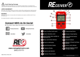
VRS Installation The VRS750 is installed using the HKN6153A interface cable. The
molded DB-25 end connects to the ASTRO mobile front connector.
The DB-25 end with the plastic housing connects to the VRS (see
Figure 2).
If an external Siren/PA is to be used, the G334AC option must be
ordered which replaces the HKN6153A cable with a HKN6154A cable,
or a separate HKN6154A cable must be ordered. To install, plug the “T”
side of the HKN6154A cable to the Siren/PA. Replace the mounting
screw on the HKN4363B cable with the double length screw. Plug this
side into the “T” cable. Plug the DB-25 end of the HKN6154A into the
VRS (see Figure 3).
Figure 2. Installing the VRS to an ASTRO Mobile
Figure 3. Installing the VRS750 with an External Siren/PA
Control Head
ASTRO Mobile
VRS750
HKN6153A
Control Head
ASTRO Mobile
Siren/PA
VRS750
HKN4363B
HKN6154A

6
Installation of the
Mounting Trunnion,
HLN6855
1. Select the location to mount your VRS750. The VRS750 must be
mounted within six feet of the mobile radio. Allow sufficient
space around the VRS750 for free air flow for cooling.
2. Using the trunnion mounting bracket as a template, mark the
positions of the holes on the mounting surface.
3. Center-punch the spots you have marked and drill a 4 mm (0.16
inch) hole at each.
4. Secure the trunnion mounting bracket with the four screws
provided (see Figure 4).
5. Connect the VRS-to-Mobile cable to the 25 pin connector on the
bottom of the VRS750.
6. Position the VRS750 in the trunnion.
7. Secure the VRS750 with the two wing screws, and the split and
flat washers provided.
Figure 4. Securing the Trunnion Mounting Bracket

7
VRS Antenna
Installation
Recommended mobile antenna installations are limited to metal body
vehicles at the center of the roof and center of the trunk deck
locations.
1. Mount the antenna using the instructions provided with the
antenna kit by the manufacturer (an antenna is not included with
the VRS models). Mount the antenna as far from the mobile radio
antenna as possible, never less than three feet. An ideal configuration
would be a roof-mounted mobile radio antenna and a trunk-
mounted VRS antenna.
2. Run the coaxial cable to the VRS750 mounting location. If
necessary, cut off the excess cable and install the cable connector.
3. Connect the antenna cable mini-UHF connector to the antenna
jack on the rear of the VRS750 (see Figure 5). A mini-UHF crimp
connector is provided with each VRS750 unit for easier
installation with a pre-existing antenna. Ensure that the
antenna’s cable connector is fully tightened. An adapter should
NOT be used between the antenna cable mini-UHF connector and
the VRS750.
VRS750
Programming
The user selectable operating parameters for the VRS750 reside in the
ASTRO mobile EEPROM during normal operation. The EEPROM
located in the VRS750 holds the tuning parameters. The VRS750
programming windows reside in ASTRO Spectra CPS and are accessible
when the “VRS-EP Option” is enabled in CPS under the Radio
Configuration --> Radio Wide --> Advanced Window (see Figure 6).
The VRS750 does not function without CPS programming and is not
pre-programmed at the factory. To ensure operational compatibility
from one unit to the next within the fleet, all of the ASTRO Mobile and
VRS750/VRS-EP systems should be programmed the same way.
Figure 5. Connecting the Antenna Cable
Mini-UHF Connector to the Antenna Jack
ANTENNA
CONNECTOR

8
Special Programming
Notes
The VRS button can be located in any of the indicator button
positions normally used for option buttons.
The VRS750 option can be enabled/disabled by a vehicle interface port
(VIP). Use the VIP Control of VRS box in the Radio Configuration
--> Radio Wide --> VRS window (see Figure 8) to enable VIP control
and to select whether the input control is active open or active closed.
Then use the Radio Configuration --> Radio Wide --> Radio VIP
window (see Figure 7) to select the VIP to be used. However, the VRS
button must still be added to the control unit if it is desired to have
the indicator light when the VRS750 is enabled. See the ASTRO Spectra
CPS user’s manual for details concerning programming the VIP.
NOTE: The ASTRO Spectra CPS user’s manual does not
indicate that the VRS button is required in order to
have the indicator light when the VIP is enabled.
Figure 6. Advanced Window
(Radio Configuration --> Radio Wide --> Advanced)
/