10 GPSMAP 4000/5000 Series Installation Instructions
The GPSMAP 4000/5000 series chartplotter is packaged with the necessary NMEA 2000 connectors and cable to either connect the GPSMAP
4000/5000 series chartplotter and GPS 19x antenna to your existing NMEA 2000 network, or to build a basic NMEA 2000 network. For more
information on NMEA 2000, visit www.garmin.com.
If your boat already has a NMEA 2000 network installed, use the included T-connectors and drop cable to connect the GPSMAP 4000/5000
series chartplotter and GPS 19x antenna to the existing network.
1. Determinetheappropriatelocationstoconnectthe
GPSMAP4000/5000serieschartplotterandGPS19x
toyourexistingNMEA2000backbone.
2. DisconnectonesideofaNMEA2000T-connectorfrom
thebackbonenearesttothelocationwhereyouwant
toconnectthechartplotter.
IfyouneedtoextendtheNMEA2000backbone,
connectanappropriateNMEA2000backbone
extensioncable(notincluded)tothesideofthe
T-connectoryoudisconnected.
3. ConnectanincludedT-connectorintheNMEA2000
backbone(forthechartplotter).
4. Routeanincludeddropcabletothechartplotterand
tothetopoftheT-connectoryouaddedtoyourNMEA
2000network.
Iftheincludeddropcableisnotlongenough,youcan
addadropcableextensionupto13ft.(4m).Ifmore
cableisneeded,addanextensiontoyourNMEA2000
backbone,basedontheNMEA2000guidelines.
5. DisconnectonesideofaNMEA2000T-connectorfrom
thebackbonenearesttothelocationwhereyouwant
toconnecttheGPS19xantenna.
IfyouneedtoextendtheNMEA2000backbone,
connectanappropriateNMEA2000backbone
extensioncable(notincluded)tothesideofthe
T-connectoryoudisconnected.
6. ConnectanincludedT-connectorintheNMEA2000
backbone(fortheGPS19xantenna).
7. RouteanincludeddropcablefromtheGPS19xantennatothetopoftheT-connectoryouaddedtoyourNMEA2000network.
Iftheincludeddropcableisnotlongenough,youcanaddadropcableextensionupto13ft.(4m).Ifmorecableisneeded,addan
extensiontoyourNMEA2000backbone,basedontheNMEA2000guidelines.
notice
If you have an existing NMEA 2000 network on your boat, it should already be connected to power. Do not connect the included NMEA 2000 power cable to
an existing NMEA 2000 network.
NOTES:
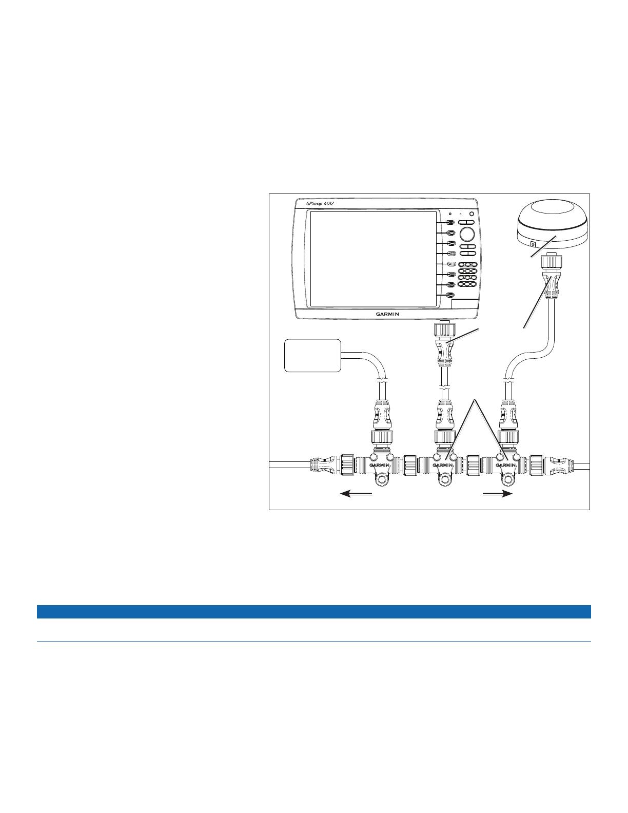
• The diagram shows only the NMEA 2000 data connection to the GPSMAP 4000/5000 series chartplotter. The chartplotter must also be
connected to power or it will not function. See page 9.
• One GPS antenna will provide position data for every device on the NMEA 2000 network. Do not connect multiple GPS antennas if you are
using multiple chartplotters.
T-connectors
(included)
Drop cables
(included)
Existing NMEA 2000 network
(not included)
GPS 19x
antenna
GPSMAP 4000/5000
series chartplotter
NMEA 2000
device
(not included)


