Page is loading ...

Installation Instructions
NOTE: Read and become fanfiliar with these instructions before beginning installation.
SAFETY CONSIDERATIONS
Installing and servicing air-conditioning equipment can be
hazardous due to system pressures and electrical components. Only
trained and qualified personnel should install or service
air-conditioning equipment. When working on air-conditioning
equipment, observe the precautions provided in literature, tags, and
labels attached to the unit.
Follow all safety codes. Wear safety glasses, protective clothing,
and work gloves. Use quenching cloth for brazing operations.
Have fire extinguisher available. Read these instructions
thoroughly and follow all warnings or cautions included in
literature and attached to the unit. Consult local building codes and
National Electrical Code (NEC), ANSI/NFPA 70, Canadian
Electrical Code CSA C22.1 and local codes and ordinances for
special requirements.
Recognize safety information. This is the safety-alert symbol/_.
When you see this symbol on the unit and in instructions or
manuals, be alert to the potential for personal injury.
Understand these signal words: DANGER, WARNING, and
CAUTION. These words are used with the safety-alert symbol.
DANGER identifies the most serious hazards which will result in
severe personal injury or death. WARNING signifies hazards
which could result in personal injury or death. CAUTION is used
to identify unsafe practices which may result in nfinor personal
injury or product and property damage. NOTE is used to highlight
suggestions which will result in enhanced installation, reliability, or
operation.
ELECTRICAL SHOCK HAZARD AND/OR UNIT
OPERATION AND DAMAGE HAZARD
Failure to follow this warning could result in personal injury or
death and/or unit operation and damage.
- Follow the National Electrical Code (NEC), ANSI/NFPA
70, Canadian Electrical Code CSA C22.1 and local codes
and ordinances for special requirements.
- For personal safety, this unit MUST BE properly grounded.
- Protective devices (fuses or circuit breakers) acceptable
for unit installations are specified on the nameplate of
each unit.
- DO NOT use an extension cord with this unit.
- Alunfinum building wiring may present special problems.
Consult a qualified electrician for assistance.
When unit is in STOP position, there is still voltage to
electrical controls.
Table 1--Package Contents
ITEM QUANTITY
Subbase Hardwire Kit Assembly 1
Electrical junction box with factory-in- 1
stalled hardwire
Hardwire routing access cover 1
Wiring access cover 1
Attachment screws (black) 6
Table 2--POWER CONNECTION CHART
UNIT MODEL
52ME- U07- - -3
52MQ- U07- - -3
52ME- U09- - -3
52MQ- U09- - -3
52ME-U12- - -3
52MQ-U12- - -3
52ME-U15- - -3
52MQ-U15- - -3
CODE OF SUBBASE HARDWIRE KIT
ASSEMBLY
30A 20A 15A
230/208 VOLT
N/A*
M-SUBBASE
-HW-30A
M-SUBBASE M-SUBBASE
- HW-20A - HW- 15A
Disconnect power to unit before wiring Subbase Hardwire Kit
by removing branch circuit fuses or turning circuit breakers
off at panel.
M-SUBBASE
-HW-15A
PERSONAL INJURY HAZARD
Failure to follow this caution may result in personal injury.
Use care when cutting support rods in filters, This may result in
flying debris and sharp rod ends.
Always wear safety goggles and appropriate protective
clothing.
52ME-U07- - -4
52MQ-U07- - -4
N/A*
52ME- U09- - -4
52MQ-U09- - -4 M-SUBBASE
52ME-U12- - -4 -HW-20A
52MQ-U12- - -4 M-SUBBASE
52ME-U15- - -4 -HW-30A
52MQ-U15- - -4
Using 30A on these units could result in damage to your unit.
265 VOLT 265 VOLT 265 VOLT

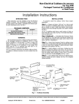
INTRODUCTION
These instructions cover the installation of the Subbase Hardwire
Accessory Kit. The kit consists of an electrical junction box, a
hardwire routing access cover, a wiring access cover, and 6
attachment screws.
GENERAL
The Subbase Hardwire Accessory Kit can be field installed to
convert a non-electrical subbase to an electrical hardwired subbase
for packaged ternfinal air conditioner (PTAC) units. See Fig. 1.
This kit can be used for both 208/230-v and 265-v applications at
15, 20 and 30 amps.
ELECTRICAL
JUNCTION BOX
ACCESSCOVE
ACCEssW' ' ° :.1
COVER ¢_¢k, SCREWS (6)
A09027
Fig. 1 - Subbase Hardwire Accessory Kit
INSTALLATION
ELECTRICAL SHOCK HAZARD
Failure to follow this warning could result in personal iniury or
death,
Disconnect all power to unit to avoid possible electrical shock
during installation,
Building power source wiring can enter subbase through any
conduit knockout hole in bottom of subbase or through the
knockouts in the electrical junction box walls.
All wiring must comply with National Electrical Code (NEC),
ANSI/NFPA 70, Canadian Electrical Code CSA C22.1 and
local electrical codes and ordinances.
NOTE: Subbase nmst be removed from wall sleeve prior to
installation of hardwire kit.
Step 1 --Disconnect all power to unit.
Step 2 --Remove the half circle conduit knockout from the
hardwire routing access cover (see Fig. 2). This will provide
additional space to route conduit from subbase to unit.
Step 3 --Route conduit out through the rectangular conduit notch
located on top front of the subbase. See Fig. 2.
MOUNTING
SiDE
TAB
/
Step 6 --Connect power to hardwire wires using field-supplied
wire nuts. See Fig. 5 for wiring.
Step 7 --Attach wiring access cover with two (2) black screws
(provided).
Step 8 --Attach subbase to wall sleeve. Subbase has side tabs for
mounting the subbase to the sleeve. Be sure hole on side tab is
lined up with pre-drilled locator hole on side of sleeve. Once
holes are aligned, attach subbase to sleeve with one (1) black screw
(provided) on each side. Do not over-tighten. See Fig. 3.
I IMPORTANT: Be sure PTAC unit is installed in wall I
I
I
sleeve before proceeding.
ATTACHMENTSCREW
A09030
Fig. 3 - Hardwire Subbase Assembly Attached to Wall Sleeve
Step 9 --Remove front panel. See Fig. 4.
A07064
Pull out at the bottom to release it from the tabs (1). Then lift up
(2).
Fig. 4 - Removing Front Panel
Step 10 --Remove junction box. See Fig. 5.
a. Remove junction box cover by removing three screws
from front (save these for later).
b. Remove junction box by taking out top, rear, and side
screws (save these for later).
BOLT
Fig. 2 - Subbase Hardwire Assembly
A09029
Step 4 --Attach hardwire routing access cover with two (2) black
screws (provided).
Step 5 --Bring power into the subbase electrical junction box
using one of the knockouts for conduit connections. See Fig. 3.
'\\
Junction box cover ",,,Junction b ,\
A07058

Fig. 5 - Junction Box Location Step 13 --Replace front panel. See Fig. 8
Step 11 --Connect Hardwire Kit Assembly. See Fig. 6.
a. Units must be installed using the appropriate Hardwire
Assembly, See Table 2.
Kit
A07641
Fig. 6 - Hardwire Kit Assembly
Step 12 --Re-install junction box and cover. See Fig. 7.
a. Re-install junction box using parts saved in Step 10,0,
b. Replace junction box cover using the one attached to access-
ory conduit, See Fig. 7.
A07639
Fig. 7 - Junction Box Cover
A07065
Place tabs over top rail (1). Push Inward at bottom until panel
snaps into place (2).
Fig. 8 - Replacing Front Panel
Step 14 --Make field connections, See Fig. 9.
CONDUIT
WIRE CONNECTOR_ /_
FIELD WIRING_ -- _WHT
HEATER WIRING /
3K WIRING PIN #4 _ #5
2K WIRING PIN #5 a #6
5K WIRING PIN #4, #5 _ #6
/
(g) CIRCUIT PLUG/RECEPTACLE_
UNIT (6) CIRCUIT
PLUG/RECEPTACLE
>UNIT WIRING
A07640
Fig. 9 - Wiring Connections
Step 15 --Reconnect branch circuit breakers.
Step 16 --Turn unit on.

Copyright 2009 CA( / BDP * 7310 W. Morris St. * hldianapolis. IN 46231 Printed in U.S.A.
Manufacturer reserves the right to change, at any time, specifications and designs without notice and without obligations.
4
Edition Date: 01/09
Catalog No: IIK-MSUBBASEHW--OI
Replaces: New
/