Page is loading ...

International Sales Division
D
LIST No.
DH 40MEY: F425
Dec. 2014
TROUBLESHOOTING GUIDE --------------------------------------------------------------------------------------------- 1
1. Troubleshooting and corrective action --------------------------------------------------------------------- 1
REPAIR GUIDE ---------------------------------------------------------------------------------------------------------------- 3
1. Precautions on disassembly and reassembly ----------------------------------------------------------- 3
STANDARD REPAIR TIME (UNIT) SCHEDULES ------------------------------------------------------------------ 19
CONTENTS
Page
PRODUCT NAME
Hitachi Rotary Hammer
Model DH 40MEY

-1-
[Bold] numbers in the description below correspond to the item numbers in the Parts List and exploded
assembly diagram for the Model DH 40MEY.
1. Troubleshooting and corrective action
Perform troubleshooting and take a necessary corrective action according to the table below if there is a
problem that cannot be solved by the corrective action described in the Handling Instructions.
Problem Cause Check Corrective action
All the four LEDs of
the display lamp
are flashing.
• Broken Controller
Set [49]
• No check needed. • Replace the Controller
Set [49] with a new
one.
Three LEDs of the
display lamp are
flashing.
• Mix-up of three
internal wires of
Stator Sensor
PCB Set [42] and
Controller Set [49]
• Check the heat-shrink tube
colors (red, black, and white)
of internal wires connecting
the Stator Sensor PCB Set
[42] and Controller Set [49].
• Correctly connect
internal wires of the
Stator Sensor PCB Set
[42] and Controller Set
[49] by their tube colors
(red, black, and white).
• Broken Controller
Set [49]
• Check the state of the
Controller Set [49] connector.
• Replace the Controller
Set [49] with a new
one.
• Broken Rotor
[134]
• Check the built-in magnet of
the fan for breaks.
• Replace the Rotor [134]
with a new one.
Two LEDs of the
display lamp are
flashing.
• Broken Controller
Set [49]
• No check needed. • Replace the Controller
Set [49] with a new
one.
One LED of the
display lamp is
flashing.
• Improperly
connected
connector cable of
the Stator Sensor
PCB Set [42]
• Check the plug-in state of the
connector cable.
(See “Reassembly of the
power supply unit” on page
12.)
• Firmly plug the
connector cable.
• Broken Stator
Sensor PCB Set
[42]
• When the connector cable is
not defective
• Replace the Stator
Sensor PCB Set [42]
with a new one.
• Broken Controller
Set [49]
• Check the plug-in state of the
Controller Set [49] connector.
• Replace the Controller
Set [49] with a new
one.
• Broken Rotor
[134]
• Check the built-in magnet of
the fan for breaks.
• Replace the Rotor [134]
with a new one.
TROUBLESHOOTING GUIDE

-2-
Problem Cause Check Corrective action
No LED of the
display lamp is ON.
• Improperly
connected
connector cable of
the Panel [112]
PCB
• Check the plug-in state of the
connector cable.
(See “Reassembly of the
power supply unit” on page
12.)
• Firmly plug the
connector cable.
• Internal wires
loosely plugged
into the Controller
Set [49] and Filter
PCB Set [58]
• Check the plug-in state of the
internal wires.
(See “Reassembly of the
power supply unit” on page
12.)
• Firmly plug the internal
wires into the Controller
Set [49] and Filter PCB
Set [58].
• Broken Controller
Set [49]
• When the Controller Set [49]
connector is not defective
• When the internal wire is not
defective
• Replace the Controller
Set [49] with a new
one.
• Broken LED • When the connector cable is
not defective
• Replace the Panel [112]
with a new one.
• Broken Filter PCB
Set [58]
• When the internal wire is not
defective
• Replace the Filter PCB
Set [58] with a new
one.
The LEDs of the
display lamp light,
but the motor does
not run.
• Internal wires
loosely connected
to the Switch [63]
• Check the plug-in state of
internal wires to the Switch
[63]. (See “Reassembly of
the power supply unit” on
page 12.)
• Firmly connect all
internal wires to the
Switch [63].
• Broken Controller
Set [49]
• When internal wires of the
Controller Set [49] are not
defective
• Replace the Controller
Set [49] with a new
one.
• Broken Switch
[63]
• When internal wires of the
Controller Set [49] are not
defective
• Replace the Switch [63]
with a new one.

-3-
Fig. 1
1. Precautions on disassembly and reassembly
WARNING: Be sure to disconnect the power cord plug from the wall outlet before conducting
repair. Otherwise, the motor may run suddenly and you could get injured.
1. Disassembly of the tool retainer
Remove the Front Cap [1] while pulling the Grip [2] in the arrow direction. Note that the Front Cap [1] is
firmly fitted to the Retainer Sleeve [19]. Insert the edge of a flat-head screwdriver or similar tool into the
gap between the Front Cap [1] and Grip [2], and then pry up the Front Cap [1] by placing the fulcrum on
the Grip [2] as shown below. You can now separate the Grip [2] from the Retainer Sleeve [19].
Remove the Stopper Ring [3] by using a retaining ring puller. You can now separate the Retainer
Washer [4], Retainer Damper (A) [5], Bit Lock Holder [6], two Bit Locks [18], Thrust Plate [7], Retainer
Spring [8], and Spring Holder (A) [9] from the Retainer Sleeve [19].
2 Disassembly of the hammering mechanism
(1) Second hammer and striker
First, remove the Bolt M5 x 12 [10] from the Cylinder Case Cover [11] and detach the Cylinder Case
Cover [11] from the Cylinder Case [13]. Remove the Bolt M6 x 25 [12] and detach the Cylinder Case
[13] from the Crank Case [89]. You can now separate Spring Holder (B) [28], Retainer Sleeve [19],
and other parts from the main body.
You can take out the Second Hammer [21] together with the Damper Holder [24], Damper [23], and
Damper Washer [22] from the detached Retainer Sleeve [19].
You can take out the Cylinder [25] together with the Lock Spring [29], Lock Sleeve [30], Clutch Spring
[31], and Clutch [32] from the main body.
Strike the end of the Cylinder [25] with a plastic hammer to pull out the Striker [26].
Disassembly
REPAIR GUIDE
[3]
Flat-head screwdriver
[19]
[2]
[1]
[4]
[6]
[7]
[5]
[18]
[9]
[8]
Fig. 2

-4-
Fig. 3
Fig. 4
(2) Piston ass’y
You can remove the piston ass’y from the main body without disassembling the Bevel Gear [34] and
Slip Clutch Ass’y [114]. Move the Connecting Rod Ass’y [39] as shown below to remove the piston
ass’y from the Crank Shaft [83].
[19]
Cylinder case ass'y
[21]
[26]
[25]
[23]
[24]
[22]
[29]
[28]
Crank case ass'y
[31]
[30]
[32]
[33]
[17]
[15]
[16]
[34]
[39]
[83]
Piston ass’y

-5-
Fig. 5
(3) First gear and crank shaft
Remove the Bolt M5 x 16 [66] and detach the Crank Cover [101] from the Crank Case [89]. Then take
out the Change Plate [105] and Slider [33] from the Crank Case [89].
Remove the Bolt M5 x 16 [66] and Bolt M5 x 12 [53], and then detach Handle (A) [64], Handle (B) [55],
and the Back Cover [60].
Remove the Bolt M6 x 45 [45] and Bolt M6 x 20 [131], and then detach the Crank Case [89] from the
Housing [48]. Disconnect the Panel [112] connector from the Controller Set [49] beforehand.
If the Slip Clutch Ass’y [114] is difficult to remove from the Crank Case [89] or Gear Cover [130], strike
it with a plastic hammer to remove it.
Wipe off grease from the Piston [38] side and the First Gear [128] side in the Crank Case [89], and
then remove the Retaining Ring [85] that retains the Ball Bearing 6203DD [87] by a retaining ring
puller, while turning the Crank Shaft [83] so that you can see the Retaining Ring [85] hole.
Place the Crank Case [89] on an adequate cradle with its Piston [38] facing down, and then use a
hand press to press down on the end surface of the Crank Shaft [83]. The First Gear [128] and Crank
Shaft [83] can be removed from the Crank Case [89].
(4) Slip clutch ass’y
Remove the Ball Bearing 629VV [126] by using
a bearing puller. Support Washer (A) [120] by
an adequate sleeve-like cradle as shown below.
Use a hand press to press the Bevel Pinion
[115] on the Spacer [125] side. Detach the
Gear Holder
[121] and Spacer [125]
from the
Bevel Pinion [115]. When removing the Second
Gear [124] from the Gear Holder [121], put
these parts in a plastic bag and disassemble in
the bag to avoid losing Spring (C) [123] and the
Needle [122].
[89]
[83]
[85]
[89]
[83]
[128]
Adequate cradle
Hand press
Fig. 6
[126]
Cradle
[120]
[124]
[115]
[125]
[121]
[123]
Hand press
[122]

-6-
Fig. 7
3. Disassembly of the motor
Firmly hold the Housing [48] and use a plastic
hammer to tap the shaft of the Rotor [134] until the
spigot joint of the Gear Cover [130] is removed from
the Housing [48].
The Rotor [134] has strong magnetic force. Firmly
hold the Housing [48] and pull out the Gear Cover
[130] from the Housing [48].
[130]
[48]
[134]
Tap the shaft of the rotor.

-7-
Fig. 8
Fig. 9
Reassembly can be accomplished by reversing the disassembly procedure. However, special attention
should be given to the following items.
1. Reassembly of the hammering mechanism and low vibration mechanism
(1) First gear and crank shaft
Press-fit Oil Seal (B) [88] to the Crank
Case [89]. Mount the O-ring [86].
Press-fit the Ball Bearing 6203DD [87].
Use a retaining ring puller to mount the
Retaining Ring [85].
Press-fit the Crank Shaft [83] to the Ball
Bearing 6203DD [87].
Insert the Feather Key [84] into the
Crank Shaft [83] groove. Support the
plane of the Crank Shaft [83] with an
adequate steel rod and use an adequate
tool to press-fit the First Gear [128].
Prior to press-fitting, make sure the
Feather Key [84] matches the key
groove of the First Gear [128].
(2) Piston
Insert the Connecting Rod Ass’y [39] into the Piston [38], and then press-fit the Piston Pin [37] from
the D8 hole (marked “ĭ2”) of the Piston [38]. Be careful not to let the Piston Pin [37] project from the
outer diameter of the Piston [38]. Mount the O-ring [36] on the Piston [38] to make the piston ass’y.
Next, turn the Crank Shaft [83] to the position shown below, and then mount the piston ass’y to the
Crank Shaft [83] from the Cylinder Case [13] side of the Crank Case [89].
The piston ass’y can be assembled even when the Bevel Gear [34] and Slip Clutch Ass’y [114] are
mounted to the Crank Case [89].
Reassembly
[84] [89]
Adequate
steel rod
[128]
[88]
[86]
[87]
[83]
[85]
[83]
[89]
[39]
[38] [36]
[37]
“ĭ2” mark
Adequate tool

-8-
Fig. 10
(3) Cylinder and retainer sleeve
Mount the Retainer Damper Washer [17], Retainer Damper (B) [16], and the Retainer Damper Holder
[15] in this order to the Retainer Sleeve [19] with the rounded surface of the Retainer Damper Washer
[17] facing that of the Retainer Sleeve [19] and the rounded surface of the Retainer Damper Holder
[15] facing that of the Retainer Sleeve [19].
Insert the Second Hammer [21] (equipped with O-ring (C) [20]), Damper Washer [22], Damper [23],
and Damper Holder [24] in this order with the rounded surface of the Damper Washer [22] facing that
of the Second Hammer [21].
Insert the assembled Retainer Sleeve [19] into the Cylinder Case [13]. Be careful not to curl the lip of
the oil seal.
Insert the Slider [33] into the outer periphery of the Bevel Gear [34] along the Crank Case [89] groove.
As shown below, push in the Slider [33] until its stopper contacts the butting position of the Crank Case
[89]. Insert so that the Clutch [32] engages with the internal claw of the Bevel Gear [34].
Insert the Striker [26] equipped with the O-ring [27] into the Cylinder [25]. Fit the Clutch Spring [31] to
the Cylinder [25], and then insert the assembled Cylinder [25] into the Crank Case [89].
Next, insert the Lock Sleeve [30] into the Crank Case [89] with the inner spline groove of the Crank
Case [89] matched with the Lock Sleeve [30] spline. Then place the Lock Spring [29] and Spring
Holder (B) [28] on the Lock Sleeve [30].
Finally, fit the protrusion of the Retainer Sleeve [19] to the Cylinder [25] groove, and then assemble the
Cylinder Case [13] equipped with the Retainer Sleeve [19]
with the Crank Case [89]
equipped with the
Cylinder [25].
[19]
[13]
[15]
[16]
[17]
[24] [23]
[22]
[25]
[31]
[28]
[30]
[32]
[33]
[34]
[26]
[29]
[35]
Note directions of [15],
[17], and [22].
[21]
[27]
[20]
Do not curl the
oil seal lip.

-9-
Fig. 11
Fig. 12
(4) Slip clutch ass’y
Press-fit the Collar [116] and Ball Bearing 6002DD [118] in this order to the Bevel Pinion [115], and
then insert the Washer [119] and Washer (A) [120] in this order. Mount the Feather Key [94] to the
Bevel Pinion [115] and press-fit the Gear Holder [121]. Insert the Second Gear [124] into the outer
periphery of the Gear Holder [121]. Apply Hitachi Motor Grease No. 29 to the inner periphery of the
Second Gear [124] in advance. Insert the ten Needles [122] upright as shown below, and then push in
ten Springs (C) [123]. Fill up the slotted groove and through-hole portions of the Gear Holder [121]
with Hitachi Motor Grease No. 29, and then press-fit the Spacer [125] and Ball Bearing 629VV [126] in
this order to the Bevel Pinion [115].
(5) Handle shaft and handle (A)
Push the Holder [73] into the Back Cover [60]
by hand. Make sure the gap of the Holder [73]
is at the bottom and the Holder [73] does not
protrude from the surface of the Back Cover
[60]. Make sure the convex mark on the Back
Cover [60] is aligned with the convex mark on
the Handle Shaft [74]. Assemble the Handle
Shaft [74] and push the four Handle Dampers
[56] into the gap between the Holder [73] and
Handle Shaft [74]. Make sure the Handle
Dampers [56] do not protrude from the end
surface of the Back Cover [60].
To mount Handle (A)
[64] and Handle (B) [55],
rotate the Handle Shaft [74] about 10°, and
then fit the Transatory Unit [57] and Handle
Shaft [74] to Handle (A) [64] and Handle (B)
[55] simultaneously.
[115]
[120]
[124]
[126]
[125]
[118]
[116]
[115]
[121]
[122]
[123]
[94]
A
A
Slotted groove in
the gear holder
Section A—A
[119]
Convex mark
Gap portion
[73]
[56]

-10-
Fig. 13
Fig. 14
(6) Reassembly of the low vibration mechanism
(a) Apply specified grease to the inner periphery of the metals in the Crank Case [89] and fill the space
between the metals with the specified grease (0.5 to 1.0 g). Specified grease is required to maintain
the low-vibration effect.
(b) Fit the Feather Key [94] to the Weight Shaft [93], insert the Weight [91] and Washer [90], and then
fit the assembly to the Crank Case [89]. Wipe off all excessive grease after inserting the Weight
Shaft [93]. The Weight Shaft [93] can be inserted into the Crank Case [89] in any posture. Mount
the Washer [90] to the opposite side of the shaft, insert the Feather Key [94], Weight [91], and
Washer M5 [108] in this order, and then secure these parts with Nut M5 [107].
NOTE: Do not alter the Washer [90] assembly order. Note that you cannot mount the Weight
[91] after first inserting the Feather Key [94].
Metals
Fill this space with
specified grease
(0.5 to 1.0 g).
Apply specified
grease to the inner
periphery of the
metals.
[89]
[90]
[91]
[93]
[94]
[90]
[94]
[108]
[107]
[93]

-11-
Fig. 15
Fig. 16
[99]
[101]
[104]
Eccentric pin
mark
Rotation and hammering
mode mark
[101]
[99]
(c) Firmly fit each Weight Spring [92] to each Weight [91] groove and Crank Case [89] groove as
shown below when assembling the four Weight Springs [92] to the Weights [91]. Note that the
low-vibration effect is lost in case a weight spring comes off due to vibration during work.
(7) Change lever
When inserting the Lever Shaft [104] into the Crank Cover [101], set the eccentric pin of the Lever
Shaft [104] on the (rotation and hammering mode) mark side of the Crank Cover [101]. Then
mount the Change Lever [99] on the Lever Shaft [104] with the mark of the Change Lever [99]
aligned with the mark of the Crank Cover [101].
[91]
Two grooves on the Weight [91]
(Total of four grooves including
those on the other side)
[89]
Four grooves on the
Crank Case [89]
[92]
[92]

-12-
Fig. 17
(8) Reassembly of the valve and felt
Make sure the Valve [111] is inserted in the Crank Case [89]. Grease will leak without the Valve [111].
After inserting the Valve [111], lock it with the Cap Screw [110]. Degrease the felt attaching portion of
the Crank Case [89], and then attach Felt (A) [109] with the hole on Felt (A) [109] matching the hole
on the Cap Screw [110]. Insert two Felts (B) [106] into the hole on the Crank Case [89].
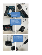
2. Reassembly of the power supply unit
(1) Rotor ass’y
Before inserting the Rotor [134] into the Housing [48], mount the Rotor [134] on the Gear Cover [130].
Without the gear cover, the Rotor [134] will be strongly attracted and fixed to the Stator Sensor PCB
Set [42] by its own magnetic force. Be careful not to let your hand be suddenly pulled by the magnetic
force of the Rotor [134].
(2) Wiring of the controller set (See Fig. 18.)
• Connect the terminals of the three internal wires (red, white, and black) coming from the Stator
Sensor PCB Set [42] to the Controller Set [49] terminals of the same colors. Insert each terminal into
the mating terminal securely until it contacts the innermost end.
• Connect the 5-wire connector of the Stator Sensor PCB Set [42] to the Controller Set [49] connector.
Do not reverse the connector orientation.
• Connect the 8-wire connector of the Panel [112] to the Controller Set [49] connector. Do not reverse
the connector orientation.
(3) Wiring of the filter PCB set (See Fig. 18.)
• Connect the two terminal-equipped internal wires of the Controller Set [49] with those of the Filter
PCB Set [58]. The internal wires can be connected in any order. Insert each terminal into the mating
terminal securely until it contacts the innermost end.
• Connect the two core-exposed internal wires of the Filter PCB Set [58] to Pillar Terminal (A) [67].
[106]
[109]
[110]
[111]
[89]

-13-
Fig. 18
(4) Wiring of the switch (See Fig. 18.)
• Connect the two core-exposed internal wires of the Controller Set [49] to the terminals No. 2 and No.
3 of the switch. These internal wires are interchangeable.
(5) Wiring of the cord (See Fig. 18.)
• Connect the core-exposed internal wires of the Cord [71] to Pillar Terminal (A) [67]. These internal
wires are interchangeable.
[63]
[112]
[42]
Check the
connector
orientation.
Check the
connector
orientation.
[49]
[58]
[68]
Interchangeable
wires
[67]
Interchangeable
wires
Red
Black
Black
Black
White
Red
Black
[71]
Interchangeable
wires
Red
Red

-14-
Fig. 19 • Specified grease (for rotary hammer drill)
Specified grease (for rotary hammer drill)
• Fill 60 g of specified grease in the Crank Case [89] on the Connecting Rod Ass'y [39] side as shown in
Fig. 20.
• Fill 0.5 to 1.0 g of specified grease to the space between the metals on both sides of the Crank Case
[89] as shown in Fig. 21.
• Apply specified grease to the inner and outer diameter portions of the Cylinder [25], sliding portion of the
Striker [26], and O-ring [27] of the Striker [26] as shown in Fig. 22.
• Apply specified grease to the inner diameter portion of the Connecting Rod Ass’y [39], outer diameter
portion of the Piston [38], and O-ring [36] of the Piston [38] as shown in Fig. 23.
• Apply specified grease to the sliding portion of the Second Hammer [21] and O-ring (C) [20] of the
Second Hammer [21] as shown in Fig. 24.
• Apply specified grease to the Weight Shaft [93] and the inner periphery of the metal in the Crank Case
[89] before inserting the Weight Shaft [93] as shown in Fig. 25.
• Apply specified grease to the inner lips of Oil Seal (A) [117] and Oil Seal (B) [88], inner and outer
diameter portions of the Bevel Gear [34], Thrust Washer [35], inner periphery of the Clutch [32], inner
diameter portion of the metal in the Cylinder Case [13], inner lip of oil seal in the Cylinder Case [13],
Damper [23], Retainer Damper (B) [16], and inner and outer peripheral polished surfaces of the
Retainer Sleeve [19].
Hitachi Motor Grease No. 29
• Fill a total of 20 g of Hitachi Motor Grease No. 29 in the Crank Case [89] on the First Gear [128] side
and the Gear Cover [130] side.
• Apply Hitachi Motor Grease No. 29 to the Needle Bearing (M661) [129], pinion portion of the Rotor [134],
and the Bit Lock [18].
Net weight Code No.
500 g 335781
60 g 335782
CAUTION: Both the viscosity and consistency of this specified grease are optimized for the
Model DH 40MEY rotary hammer, in order to prolong its service life. Therefore,
applying ordinary grease used for conventional models (e.g. DH 40MRY) to the
Model DH 40MEY may dramatically shorten its service life.
Lubrication points and types of lubricant
60 g
500 g

-15-
Fig. 22
Fig. 23 Fig. 24
Fig. 20 Fig. 21
Crank Case [89]
Cylinder [25]
O-ring [27]
Striker [26]
O-ring [36]
Needle Bearing [40]
O-ring (C) [20]
Second Hammer [21]
Piston Pin [37]
Crank Case [89]
Metal
Fill 60 g of
grease.
(1) Apply specified grease to the Cylinder [25] (inner and outer diameter portions), Striker [26], and O-ring [27].
(2) Insert the Striker [26] into the Cylinder [25] in the arrow direction until it contacts the innermost end.
(3) Apply a small amount of specified grease to the inner diameter portion of the Cylinder [25] once more to give
a thin film of grease.
Crank Case [89]
(Fill the space between the metals with
0.5 to 1.0 g of grease.)
Piston [38]
Slider [33]
Apply to inner and outer
polished surfaces.
Apply to outer peripheral
sliding surfaces.
Connecting Rod Ass’y [39]
Apply to outer peripheral
sliding surfaces.

-16-
Fig. 25
Weight Shaft [93]
Crank Case [89]
Metal
Apply grease to the inner diameter portion of
the metal (on both sides of the crank case.)

-17-
Be sure to apply TB1401 screw locking agent to the threads of the following screws and bolts. Otherwise,
the screw or bolt loosened by vibration may cause damage to the tool body.
M8 Cap Screw [110] ··························································· 3.92 N•m (40 kgf•cm)
M6 Bolt M6 x 45 [45] ·························································· 9.8 N•m (100 kgf•cm)
Bolt M6 x 20 [131] ························································ 9.8 N•m (100 kgf•cm)
Bolt M6 x 25 [12] ·························································· 9.8 N•m (100 kgf•cm)
M5 Bolt M5 x 16 [66] ·························································· 7.84 N•m (80 kgf•cm)
Bolt M5 x 12 [53] ·························································· 4.9 N•m (50 kgf•cm)
Bolt M5 x 16 [66] ·························································· 3.92 N•m (40 kgf•cm)
Bolt M5 x 12 [10] for mounting the tail cover ······················· 4.9 N•m (50 kgf•cm)
Bolt M5 x 12 [10] for mounting the cylinder case cover ·········· 3.92±0.49 N•m (40±5 kgf•cm)
Nut M5 [107] ······························································· 2.94±0.49 N•m (30±5 kgf•cm)
M4 Bolt M4 x 12 [113] ························································· 0.49 N•m (5 kgf•cm)
D5 Screw D5 x 55 [41] ························································ 2.94±0.49 N•m (30±5 kgf•cm)
D4 Screw D4 x 16 [70] ························································ 1.96±0.49 N•m (20±5 kgf•cm)
Screw D4 x 20 [75] ······················································· 1.96±0.49 N•m (20±5 kgf•cm)
After completing disassembly and repair, measure the insulation resistance and dielectric strength.
Insulation resistance: 7 Mȍ or higher (as measured with a 500 VDC megohm tester)
Dielectric strength: 4,000 VAC/1 minute, with no abnormalities ----- 220 V – 240 V
(and 110 V for UK products)
2,500 VAC/1 minute, with no abnormalities ---- 110 V – 127 V
(except UK products)
After no-load operation for 30 minutes, the no-load current values should be as follows:
Voltage
110 V 120 V 127 V 220 V 230 V 240 V
Current max.
4.1 A 3.7 A 3.5 A 2.1 A 2 A 1.9 A
Tightening torque
Insulation test
+1.96
0
+20
0
+1.96
0
+20
0
+1.96
0
+20
0
+1.96
0
+20
0
+0.98
0
+10
0
+20
0
+1.96
0
+1.96
0
+20
0
+5
0
+0.49
0
+0.98
0
+10
0
No-load current value

-18-
Fig. 26 • Wiring diagram
Connecting diagram
Panel
board
set
5-wire
Switch
Pilla
r
terminal
Controller set
Stator sensor
board set
M
Filter
board set
Cord
Red Red
Black
Black
Black Black
Red Red
White White
8-wire

-19-
MODEL
Variable
Fixed
10 20 30 40 50 60
DH 40MEY
General assembly
Back Cover
Transatory
Unit
Crank Case
Cover
Weight
Cylinder
Case
Retainer
Sleeve
Retainer
Damper (B)
Retainer
Damper
Holder
Second
Hammer
Damper
Damper
Holder
Controller
Set
Panel
Cyliner
Striker
O-ring
Clutch
Lock Sleeve
Spring
Holder (B)
Slider
Piston
O-ring
Connecting
Rod Ass’y
Gear Cover
Rotor
Ball Bearing
6201DD
Ball Bearing
629VV
Crank Shaft
Ball Bearing
6203DD
First Gear
Slip Clutch
Ass’y
Bevel Gear
Housing
Stator
Sensor
PCB Set
Crank Case
Work Flow
Handle (B)
Handle (A)
Switch
Filter
PCB Set
Cord
Cord Armor
Tail Cover
Crank Cover
Change
Lever
Guide Plate
Lever Shaft
Change
Plate
Front Cap
Grip
Cylinder
Case Cover
Retainer
Washer
Retainer
Damper (A)
Bit Lock
Holder
Bit Lock
Thrust Plate
Spring
Holder (A)
STANDARD REPAIR TIME (UNIT) SCHEDULES
/