Page is loading ...

LEDIMPORTANTSAFETYINSTRUCTIONS
C
Toreducetheriskofdeath,personalinjuryorpropertydamagefromfire,electricshock,fallingparts,cuts/abrasions,and
otherhazardspleasereadallwarningsandinstructionsincludedwithandontheluminaireboxandallluminairelabels.
Beforeinstalling,servicing,orperformingroutinemaintenanceuponthisequipment,followthesegeneralprecautions.
Installationandserviceofluminairesshouldbeperformedbyaqualifiedlicensedelectrician.
Maintenanceoftheluminairesshouldbeperformedbyperson(s)familiarwiththeluminaires’constructionandoperation
andanyhazardsinvolved.Regularluminairemaintenanceprogramsarerecommended.
Itwilloccasionallybenecessarytocleantheoutsideoftherefractor/lens.Frequencyofcleaningwilldependonambient
dirtlevelandminimumlightoutputwhichisacceptabletouser.Refractor/lensshouldbewashedinasolutionofwarm
waterandanymild,non‐abrasivehouseholddetergent,rinsedwithcleanwaterandwipeddry.Shouldopticalassembly
becomedirtyontheinside,wiperefractor/lensandcleaninabovemanner,replacingdamagedgasketsasnecessary.
DONOTINSTALLDAMAGEDPRODUCT!Thisluminairehasbeenproperlypackedsothatnopartsshouldhavebeen
damagedduringtransit.Inspecttoconfirm.Anypartdamagedorbrokenduringorafterassemblyshouldbereplaced.
Recycle:ForinformationonhowtorecycleLEDelectronicproducts,pleasevisitwww.epa.gov.
Theseinstructionsdonotpurporttocoveralldetailsorvariationsinequipmentnortoprovideeverypossiblecontingency
tomeetinconnectionwithinstallation,operation,ormaintenance.Shouldfurtherinformationbedesiredorshould
particularproblemsarisewhicharenotcoveredsufficientlyforthepurchaser’sorowner’spurposes,thismattershouldbe
referredtoAcuityBrandsLighting,Inc.
READ AND FOLLOW ALL SAFETY INSTRUCTIONS!
SAVE THESE INSTRUCTIONS AND DELIVER TO OWNER AFTER INSTALLATION
Disconnectorturnoffpowerbefore
installationorservicing.
Verifythatsupplyvoltageiscorrectby
comparingitwiththeluminairelabel
information.
Makeallelectricalandgrounded
connectionsinaccordancewiththeNational
ElectricalCode(NEC)andanyapplicable
localcoderequirements.
Allwiringconnectionsshouldbecapped
withULapprovedrecognizedwire
connectors.
WARNING
RISKOFELECTRICSHOCK
Allowlamp/luminairetocoolbefore
handling.Donottouchenclosureorlight
source.
Followallmanufacturer’swarnings,
recommendationsandrestrictionsfor:driver
type,burningposition,mounting
locations/methods,replacementand
recycling.
Do not exceed maximum wattage marked
on luminaire label.
WARNING
RISKOFBURN
Wearglovesandsafetyglassesatalltimes
whenremovingluminairefromcarton,
installing,servicingorperforming
maintenance.
Avoiddirecteyeexposuretothelightsource
whileitison.
CAUTION
RISKOFINJURY
Keepcombustibleandothermaterialsthat
canburn,awayfromlamp/lens.
Donotoperateincloseproximityto
persons,combustiblematerialsor
substancesaffectedbyheatordrying.
CAUTION
RISKOFFIRE

LEDIMPORTANTSAFETYINSTRUCTIONS
Please see product specific installation instructions for additional warnings or any applicable FCC or other regulatory
statements.
Failure to follow any of these instructions could void product warranties. For a complete listing of product Terms and
Conditions, please visit www.acuitybrands.com.
OurBrands Indoor/Outdoor IndoorLighting OutdoorLighting Controls
LithoniaLighting Gotham AmericanElectricLighting DARKTOLIGHT
CarandiniMarkArchitecturalLighting AntiqueStreetLamps LightingControl&Design
HolophanePeerlessHydrelROAM
RELOCRenaissanceLightingTersenSensorSwitch
LightConceptsWinonaLightingSynergy
AcuityBrandsLighting,Inc.assumesnoresponsibilityforclaimsarisingoutofimproperorcarelessinstallationorhandlingofitsproducts.
ABL LED General Warnings, Form No. 503.203
© 2010 Acuity Brands Lighting, Inc. All rights reserved. 12/01/10
Neverconnectcomponentsunderload.
Donotmountorsupporttheseluminairesinamannerthatcancuttheouterjacketordamagewire
insulation.
Unlessindividualproductspecificationsdeemotherwise:NeverconnectanLEDproductdirectlytoa
dimmerpack,occupancysensors,timingdevices,orotherrelatedcontroldevices.LEDluminairesmust
bepowereddirectlyoffaswitchedcircuit.
Unlessindividualproductspecificationsdeemotherwise:Donotrestrictluminaireventilation.Allowfor
somevolumeofairspacearoundluminaire.AvoidcoveringLEDluminaireswithinsulation,foam,or
othermaterialthatwillpreventconvectionorconductioncooling.
Unlessindividualproductspecificationsdeemotherwise:Donotexceedluminairesmaximumambient
temperature.
Onlyuseluminaireinitsintendedlocation.
ElectrostaticDischarge(ESD):ESDcandamageLEDluminaires.Personalgroundingequipmentmustbe
wornduringallinstallationorservicingoftheunit.
DonottouchindividualelectricalcomponentsasthiscancauseESD,shortenlamplife,oralter
performance.
Somecomponentsinsidetheluminairemaynotbeserviceable.Intheunlikelyeventyourunitmay
requireservice,stopusingtheunitimmediatelyandcontactanABLrepresentativeforassistance.
Alwaysreadtheluminairescompleteinstallationinstructionspriortoinstallationforanyadditional
luminairespecificwarnings.
CAUTION: RISK OF PRODUCT
DAMAGE

HOLOPHANE
®
Wallpack
®
Full Cutoff Installation and
LED Luminaire (HLWCP2) Maintenance
Manual
IM‐438‐B
Index
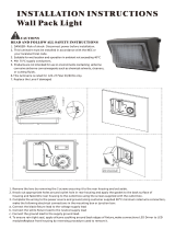
Figure 1
GR2673
1 Introduction
1.1 Product Description. The Wallpack® Full Cutoff
LED luminaires have been designed and tested in
accordance with applicable UL/CSA standards and are
suitable for use in wet locations. Installation is limited to
wall mount only. This luminaire is not suitable for up-light
applications. Luminaire max weight is 24 lbs.
2 Installation
2.1 Tools and Materials Required.
TABLE 1. Installation Tools and Materials
2.2 Mounting Luminaire to Wall
2.2.1 Loosen the 6 screws that hold the front heatsink to
the electrical housing (figure 2)
2.2.2 Fully separate the front heatsink from the electrical
housing by pulling the heatsink directly away from the
electrical housing. Disconnect hooks and wires or wire
harnesses and set the heatsink aside where it will not be
damaged. When disconnecting any wiring, do not
remove any wire labels.
Figure 2
GR2674
2.2.3 Drill out necessary anchoring holes at indicated
drill points. Drill points are within the dashed box shown
on figure 3.
DESCRIPTION SECTION
Introduction 1
Installation 2
Tools and Materials Required 2.2
Wirin
g
the Luminaire
–
Std. Luminaire 2.3
Wiring the Luminaire – Emergency
Batter
y
Pack
(
EM Option
)
2.4
Wiring the Luminaire – Two
Independent Circuit
(
2CI Option
)
2.5
Attaching Heatsink to Electrical
Housin
g
2.6
Optional 0-10V DC Dimmin
g
Controls 2.7
Maintenance 3
Limited Warranty and Limitation of
Liabilit
y
4
Field Ad
j
ustable Output
(
AO
)
Tables 5
DESCRIPTION USE
Slot-head screwdriver
(
required
)
Electrical housing
access
Phillips-head screwdriver
(
recommended
)
Drill and bit sized per fastener
Drilling mounting holes
into electrical housin
g
Mounting fastener (variable;
must be appropriate size and
thread for mountin
g
substrate
)
Mounting luminaire
Silicon Sealant or equivalent
Sealing luminaire
against water intrusion
after installation

HOLOPHANE
®
Wallpack
®
Full Cutoff Installation and
LED Luminaire (HLWPC2) Maintenance
Manual
IM‐438‐B
Figure 3
GR2675
2.2.4 For conduit entry or J-Box mounting, remove the
appropriate threaded plug on the electrical housing
2.2.5 Insert the supply wires or thread conduit through
the hole and secure housing to the wall using fasteners,
not included, that are appropriate for the size and weight
of the luminaire as well as the substrate the luminaire is
being mounted to.
2.2.6 Apply a continuous bead rubber silicon to seal the
back housing to the wall.
2.2.7 Apply a continuous bead rubber silicon to fully seal
any unused conduit entry points.
2.3 Wiring the Luminaire – Standard Luminaire
2.3.1 Using the provided chains and hooks, hang the
heatsink on the electrical housing for temporary support
during wiring.
2.3.2 Check Voltage to ensure the line voltage matches
the voltage range shown in the luminaire description on
the fixture label.
2.3.3 Reconnect any wiring that had been undone when
removing the heatsink from the electrical housing.
2.3.4 Connect the line voltage supply wires to the
luminaire input wires using the pre-installed lever nuts.
2.4 Wiring the Luminaire – Emergency Battery Pack
(EM) Luminaires only
2.4.1 Follow steps 2.3.1 to 2.3.3
2.4.2 Connect the line voltage supply wires to the
luminaire input wires using the pre-installed lever nuts.
For the emergency battery pack, both the switched
(white/red wire from battery) and unswitched
(orange/black wire from battery) lines are run through
surge protection devices. The unswitched line will be
labeled on the surge protection device.
2.4.3 Connect the battery pack inverter (red and white
wires with clear, plastic caps) to enable the battery back-
up
CAUTION: The emergency battery pack must be
allowed to charge for 24 hours prior to testing operation.
The battery will continuously discharge until it is drained
and will begin charging when the luminaire is energized.
CAUTION: Luminaires with an emergency battery pack
cannot be mounted higher than 10.74 ft. from the ground
in order to comply with UL emergency lighting 1-ft candle
criteria
2.5 Wiring the Luminaire – Two Independent Circuit
(2CI) Luminaires only
2.5.1 Follow steps 2.3.1 to 2.3.3
2.5.2 Connect the line voltage supply wires to the
luminaire input wires using the pre-installed lever nuts.
For the 2CI option, there should be 2 identical drivers
present in the luminaire. The driver that is intended to be
powered by the building’s inverter has an “unswitched”
label from the factory. The wire color for the unswitched
line will be variable depending on the performance
package chosen.
2.6 Attaching Heatsink to Electrical Housing (Figure
4)
2.6.1 Bring the heatsink close to the electrical housing
and insert the 4 guiding pins on the heatsink into the 4
guiding holes in of the electrical housing
2.6.2 Making sure not to pinch any wires or chains, slide
the heatsink until it makes contact with the electrical
housing.
2.6.3 Tighten the 6 screws to 20-25 in-lbs. to ensure a
watertight seal and a secure connection of the heatsink
to the electrical housing.
WARNING
FAILURE TO TIGHTEN HOUSING SCREWS COULD
CAUSE LUMINAIRE TO FALL RESULTING IN
INJURY, DEATH OR SERIOUS PROPERTY DAMAGE.
AVERTISSEMENT
NE PAS SERRER CORRECTEMENT LA VIS DE
RÉGLAGE PEUT PROVOQUER LA CHUTE DE LA
FIXATION ET CAUSER DES BLESSURES,
PROVOQUER LA MORT OU DE SÉRIEUX
DOMMAGES MATÉRIELS.
Figure 4
GR2676
3” mount
5” mount
4” mount

HOLOPHANE
®
Wallpack
®
Full Cutoff Installation and
LED Luminaire (HLWPC2) Maintenance
Manual
IM‐438‐B
2.7 Optional 0-10V DC Dimming Controls Information
2.7.1 Certain control options available with the
Wallpack® Full Cutoff LED luminaire have 0-10V DC
dimming capabilities. General information for each is as
follows:
2.7.2 For the field adjustable output (AO) module, the
default setting is position 8 on the dial, which
corresponds to 100% output. Output and can be
adjusted by rotating the center dial. See tables 2-6 for
additional dial settings and their corresponding outputs
based on performance package. AO Tables are included
on the last page of this installation manual.
2.7.3 For the occupancy sensor options (MASL &
MASH), see luminaire spec sheet for specific mounting
height information but in general the MASL option
mounting height should not exceed 15’ and the MASH
option mounting height should be between 15-30’ –
Specific programming instructions for these devices is
included in a separate document, included with the
luminaire.
2.7.4 The part-night dimming (PND) option requires no
special steps – the device comes preprogrammed.
2.7.5 For the NEMA twist-lock photocontrols (P3 and P7
options), installed control nodes are sold separately and
are not supported by Holophane product support.
3 Maintenance
3.1 Electrical Component Replacement
3.1.1 Disconnect power to the luminaire location before
maintenance.
3.1.2 Open luminaire by loosening 6 heatsink screws
and removing the heatsink from the electrical housing.
Depending on the device being serviced/replaced it may
be easiest to completely remove the heatsink from the
electrical housing. Drivers and fuses are mounted to the
heatsink, surge devices are mounted to the electrical
housing.
3.1.3 Tag leads before disconnecting if they are not
already labeled.
3.1.4 Replace components using Holophane approved
replacement parts.
3.1.5 Re-connect electrical leads. See sections 2.3, 2.4,
or 2.5 depending on luminaire configuration.
3.1.6 Reattach heatsink to electrical housing. See
section 2.6.
3.2 Heatsink - Optical Housing
3.2.1 There are no user serviceable parts in the optical
housing portion of the heatsink.
4 Limited Warranty and Limitation of Liability
4.1 5-year limited warranty. Complete warranty terms
located at:
www.acuitybrands.com/CustomerResources/Terms_and
_Conditions

HOLOPHANE
®
Wallpack
®
Full Cutoff Installation and
LED Luminaire (HLWPC2) Maintenance
Manual
IM‐438‐B
5 Adjustable Output (AO) Tables
P10 - AS and AH
A
O Position % Lumens % Watta
g
e
8 100% 100%
7 94% 95%
6 83% 82%
5 71% 69%
4 59% 57%
3 46% 45%
2 34% 33%
1 21% 21%
P20 - AS and AH
A
O Position % Lumens % Watta
g
e
8 100% 100%
7 95% 94%
6 84% 80%
5 73% 67%
4 61% 54%
3 48% 42%
2 35% 30%
1 21% 18%
P30 - AS and AH
A
O Position % Lumens % Watta
g
e
8 100% 100%
7 95% 94%
6 84% 80%
5 73% 67%
4 61% 54%
3 48% 42%
2 35% 30%
1 21% 18%
Field Adjustable Output Module
The Field Adjustable Output (AO) module is an onboard
device that adjusts the light output and input wattage to
meet site specific requirements, allowing a single fixture
configuration to be flexibly applied in many different
applications. The AO option is available on the HLWPC2
series.
P40 -
A
S and AH
A
O Position % Lumens % Watta
g
e
8 100% 100%
7 95% 95%
6 85% 82%
5 74% 68%
4 62% 55%
3 49% 43%
2 36% 30%
1 21% 17%
P50 -
A
S and AH
A
O Position % Lumens % Watta
g
e
8 100% 100%
7 96% 95%
6 86% 81%
5 75% 68%
4 64% 55%
3 51% 42%
2 37% 29%
1 22% 17%
Acuity Brands Lighting, Inc.
3825 Columbus Rd., Granville, OH 43023
IM-438-A 10/12 ©2017 Acuity Brands Lighting, Inc.
All Rights Reserved.
Visit our web site at www.holophane.com
/