Page is loading ...

DIS FNG
Simplex Fire Products -
Fault & Assistance Guide

1.0 Identifying Simplex® 4100 Series Faults .......................................................................................... 3
1.1 4100 SERIES - OVERVIEW ................................................................................................................... 4
1.2 4100U BASIC OPERATIONS ................................................................................................................ 5
1.3 OPERATOR INTERFACE COMMANDS ..................................................................................................... 6
1.1.1 Resetting 4100 Latched Faults & Rebooting CPU .................................................. 7
1.4 INDEX – QUICK VIEW ........................................................................................................................... 8
1.1.2 Loop Card Faults ..................................................................................................... 9
1.1.2.1 Card Missing/Failed ............................................................................................... 10
1.1.2.2 Correct Card Abnormal .......................................................................................... 10
1.1.2.3 Short Circuit Abnormal ........................................................................................... 10
1.1.2.3.1 Class „A‟ Abnormal ................................................................................................ 11
1.1.2.3.2 Channel Failure Abnormal ..................................................................................... 11
1.1.2.3.3 Channel Initialization Abnormal ............................................................................. 11
1.1.2.3.4 Extra Device........................................................................................................... 12
1.1.2.3.5 IDNet Dipswitch Settings ....................................................................................... 12
1.1.3 Addressable Device Faults .................................................................................... 13
1.1.3.1.1 No Answer ............................................................................................................. 13
1.1.3.1.2 Head Missing ......................................................................................................... 14
1.1.3.1.3 Wrong Device ........................................................................................................ 15
1.1.3.1.4 Bad Answer............................................................................................................ 16
1.1.3.1.5 Extra Device........................................................................................................... 17
1.1.3.1.6 Output Abnormal .................................................................................................... 18
1.1.3.1.7 Alarm Verification Tally Exceeded ......................................................................... 18
1.1.3.1.8 Detector LED Operation ........................................................................................ 18
1.1.3.1.9 Device DIP Switch Settings ................................................................................... 18
1.1.3.1.10 End of Line Resistors ............................................................................................. 19
1.1.5 4100-0157A Battery Charger Faults ...................................................................... 21
1.1.6 Positive/Negative Earth Ground Faults ................................................................. 23
1.1.6.1 Earth Ground Fault Detecting and Locating .......................................................... 23
2.0 4100 Crash Codes – General Information....................................................................................... 25
2.1 4100 CRASH CODES – GENERAL INFORMATION ................................................................................. 26
2.2 4100-FAMILY GENERAL CRASH CODES TABLE .................................................................................. 27
2.3 4100-FAMILY GENERAL CRASH CODES TABLE (CONTINUED) ............................................................. 28
3.0 Identifying Faults on the GCC, IMS & TrueSite Graphics & Network .......................................... 29
3.1 IDENTIFYING FAULTS ON THE GRAPHICS – GENERAL INSTRUCTIONS ................................................... 30
3.1.1 GCC, IMS & TrueSite Workstation Graphical Control Centre ............................... 30
3.2 DISPLAYED FAULT FORMAT............................................................................................................... 31
3.2.1 Fault Type .............................................................................................................. 32
3.3 NETWORK FAULTS ............................................................................................................................ 33
3.3.1 Common Trouble Point for Node ........................................................................... 33
3.3.2 Card Trouble for Node ........................................................................................... 33
3.3.3 Network Operating in Degraded Style 7 ................................................................ 33
3.3.4 Network Initialization Incomplete ........................................................................... 33
3.3.5 Node Missing/Failed .............................................................................................. 33
3.3.6 System Pseudo Status for Node ........................................................................... 33
3.3.7 Version Mismatch .................................................................................................. 33

Page 2 of 60
4.0 Identifying F3200 Faults ................................................................................................................... 34
4.1 RECALL SYSTEM FAULTS .................................................................................................................. 35
4.1.1 Function ................................................................................................................. 35
4.1.2 Operating Sequence .............................................................................................. 35
4.2 LIST OF SYSTEM FAULTS – NON-NETWORKED ................................................................................... 36
4.3 GLOSSARY OF ABBREVIATIONS ......................................................................................................... 39
5.0 Identifying faults on a QE90 ............................................................................................................. 41
5.1 QE90 SERVICE ISOLATION MODE – FAULT DISPLAY .......................................................................... 42
5.2 ECP VERSIONS 2.XX/4.XX/6.XX – SYSTEM FAULT DISPLAY ................................................................. 43
5.3 AUDIO LINE FAULT ............................................................................................................................ 45
5.3.1 Speaker Line Fault/Amp Fault ............................................................................... 45
5.3.2 Amplifier LED Configurations................................................................................. 45
5.3.3 Speaker Tapping Adjustments............................................................................... 46
5.4 STROBE LINE FAULT ......................................................................................................................... 47
5.4.1 Strobe Output Considerations ............................................................................... 47
STROBE RELAY DRIVER MODULE AND STROBE LIGHT CONNECTION......................................................... 48
5.4.2 Cable Sizing ........................................................................................................... 48
TABLE 1: CABLE GAUGES ..................................................................................................................... 48
5.4.3 Links and DIP Switches ......................................................................................... 49
TABLE 2: LINK SETTINGS AND THEIR CORRESPONDING OUTPUTS ............................................................. 49
TABLE 3: DIP SWITCHES 1 – 4 – SELECT CARD ADDRESS ....................................................................... 49
TABLE 4: DIP SWITCHES 5 – 8 – SELECT MODE FOR POWERED OUTPUTS .............................................. 50
5.4.4 STBM9008 Board Installation ................................................................................ 50
5.5 BGA OR FIP FAULT .......................................................................................................................... 51
TABLE 5: DIP SWITCH SETTINGS ........................................................................................................... 51
5.6 WIP LINE FAULT ............................................................................................................................... 52
5.7 PA SPEECH, SPARE SPEECH, WIP SPEECH, COMMS AND SPARE COMMS CABLE FAULTS .................. 53
5.8 ECP FAILURES ................................................................................................................................. 54
5.8.1 MECP and SECP Failure ....................................................................................... 54
5.8.2 WIP MECP and SECP Failure ............................................................................... 54
5.8.3 Paging Console Failure ......................................................................................... 54
5.9 ECM NETWORKED SYSTEMS............................................................................................................. 54
5.10 ECM NETWORKED SYSTEM – SYSTEM FAULT DISPLAY ...................................................................... 55
5.11 QE90 FAULT REGISTER .................................................................................................................... 56
6.0 National Contact Directory ............................................................................................................... 59
6.1 CONTACT US .................................................................................................................................... 60

1.0 Identifying Simplex® 4100
Series Faults

Page 4 of 60
1.1 4100 Series - Overview
The 4100 Series was released onto the Australian Market in 1990.The first version supported 512 devices or
points. It was replaced with the 4100+ in 1993, which supported 1000 points & the networking of up to 99
panels. The 4100A was a localized version of the 4100+ & has the FireFighter Interface as per AS4428.1.
All versions use the same metalwork & expansion cards.
In 2004, the 4100U was released. This is the new generation of 4100 series panels & has many new
software features & new, smaller expansion cards. It is still fully compatible with the old 4100 expansion
cards. The visible difference is the 4100U has raised rubber keys on the Operator Interface.
What is it? It is a fully modular Fire Detection & Control System. From 8 conventional circuits through to
2,000 conventional, addressable or a mix input & output of circuits, you simply add cards & cabinets to house
them – up to 119 cards per CPU. Connection between cabinets (that are part of the same unit) is a multi-
conductor harness, containing power & communications.
The 4100 series supports up to 31 remote units via an RUI (Remote Unit Interface). A unit can be 4100
cabinets full of cards, a mimic panel - up to 2000 LEDs & switches (2 or 3 position switches), a remote LCD,
flatpack 24Point I/O modules (multiple flatpack I/O modules located together count as 1 unit). A system can
have up to 4 RUI loops per CPU.
For larger or multi-building sites, multiple 4100 series panels can be networked together, up to 99 panels or
PC based graphic stations (each panel or station is called a Node)
The 4100 series has comprehensive built in diagnostics & the ability to display all details of each card &
addressable device. While the diagnostic & detail display details are beyond this guide‟s intent, a full range of
technical information is available on the Simplex website: www.simplexfire.com.au
Each 4100 consists of a CPU Card & up to 119 addressable expansion cards:
5004 - 8 conventional monitor zones [ZN].
3003 - 8 SPDT relays [AUX] & 8 feedback inputs [FB].
4321 - 6 supervised relay outputs [SIG].
3024 - 24 input or output relays [I/O].
0157 - Power supplies.
0110 - MAPnet addressable loop [M].
0113 - Dual RS232/2120 interface [PORT].
0304 - Remote sub-panel/LCD/mimic panel interface [RUI].
0154 – VESDA High Level Interface.
0301 - 64 LED/64 switch controller.
1288 - 64/64 Led Switch Controller
3101AU - 250 Point IDNET Addressable Loop PDI [ID}
0160 - Fire Panel Internet Interface Module
0620 - 4100U Basic Transponder Interface Card
0302A - 6 EWIS amplifier interface.
0205A - Master WIP phone.
Note: The cards listed above are the most commonly used types.
The 4 digit number is the card type & the identifier in square brackets is the physical point type.
Examples:
The first 5004 card contains points ZN1 to ZN8, the second 5004, ZN9 to ZN16.
The first 3024 card contains points I/O1 to I/O24, the second 3024, I/O25 to I/O48.
The first 0110 card contains points M1-1 to M1-127, the second 0110, M2-1 to M2-127.

Page 5 of 60
1.2 4100U Basic Operations
The Fire Panel display consists of two sections – the Operator
Interface (upper section) and the Zone Isolate pushbutton switches &
indicators (lower section). Fire detectors are grouped into zones
(searchable grouped areas). Zones can be Isolated by pressing the
zone‟s isolate pushbutton on the panel – this prevents an alarm in
that group from activating the panel outputs. When a non-isolated
detector detects an alarm, the fire panel rings the bell, calls the fire
brigade, and activates the Warning or Evacuation System along with
any other programmed functions (site specific).
The Operator Interface indicates common Alarm, Fault & Isolation
Status on LEDs, and point (detector) status on the LCD. When an
Alarm, Fault or Isolation occurs, the buzzer will operate until the
corresponding „Acknowledge‟ (e.g. Fire Alarm Ack) key is pressed.
The panel is reset by pressing „System Reset.‟ If the alarm won‟t
reset the point may still be activated (i.e. detector is still in alarm).
Press „Fire Alarm Ack‟ when the point alarm is displayed, then press
„Disable,‟ „Enter.‟ Press „Fault Ack‟ (to acknowledge the fault caused
by disabling a point), then press SYSTEM RESET again. The
disabled detector must be re-enabled when the condition is cleared.

Page 6 of 60
1.3 Operator Interface Commands
The table shown below includes some general front panel commands for quickly navigating through system
components. In addition output points can be controlled by following the below steps then commanding the
point via the On/Off/Auto keys. Manually controlling output points will create a fault on the LCD display, and
to clear these faults each manually altered output will need to be set back to its AUTO state.
Press
These Keys to Select Points
Enter
Point Data
ZONEᅠ+ Number + Enter
(4100A Only)
Enter the number of a zone. After pressing enter, use
the Previous/Next keys to scroll through the zone
points.
SIGᅠ+ Number + Enter
Enter the number of a signal circuit
AUXᅠ+ Number + Enter
Enter the number of an auxiliary relay point
FBᅠ+ Number + Enter
Enter the number of a feedback point
IOᅠ+ Number + Enter
Enter the number of a 24-Point I/O point
IDNet (4100U) / Mapnet (earlier 4100) + Channel-
Device + Enter
For Channel (loop), enter the number of the IDNet,
MAPNET, or VESDA channel. Insert a dash using the
NET key. Enter the number of the addressable
device.
P + Number + Enter
Enter the number of a digital pseudo point
A + Number + Enter
Enter the number of an analog pseudo point
L + Number + Enter
Enter the number of a list pseudo point
NET + Number + Enter
Enter the number of the network node. When the
screen prompts you to select the type of point (Zone,
Signal, etc.), press the Entry Keypad key
corresponding to that type of point, enter the number
of the point, and press Enter.
ADDR + Card-Point-Subpoint + Enter
Enter the number of the card, insert a dash (using the
NET key), and enter the number of the subpoint.

Page 7 of 60
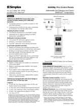
1.1.1 Resetting 4100 Latched Faults & Rebooting CPU
When fault finding the Simplex® 4100U Fire Detection Panel some IDNet/MAPNet & RUI faults will „latch‟
and not clear without the use of the „System Reset‟ button (described on a previous page). If all else fails, to
clear latched faults or some networking issues it may be warranted to use a CPU Reboot otherwise known
as a Warm-Start.
To perform a Warm-Start, gain access to the CPU card. The CPU card is generally the only legacy card
(vertically mounted) with its components side facing in a different direction (relative to other cards mounted in
a similar fashion) – otherwise it will be the only card in the panel with a small, flat and round ram battery
located on it. Once located, find the small push-button switch located on the bottom edge of the card (4100U
CPU card shown below). Push this button and the panel will then reinitialize. Allow 2-5mins for the panel to
become fully active and re-establish communications with all its associated devices.
NOTE: Starting the panel from a powered-down state is referred to as a cold-start.

Page 8 of 60
1.4 Index – Quick view
Loop Card Faults
Card Missing Failed (Card Inserted)
Correct Card
Short Circuit
Class A
Channel Failure
Channel Initialization
Extra Device
Card DIP Switch
Addressable Device Faults
No Answer
Head Missing
Wrong Device
Bad Answer
Extra Device
Output Abnormal
Detector LED Operation
Device LED Operation
DIP Switch Table
End of Line Resistor Values.
Hints & Tips
NOTE - It is vital that the Loop card is in
NORMAL status before addressable
device fault finding is started.
!

Page 9 of 60
1.1.2 Loop Card Faults
Description:
If the Loop card (MAPNET or IDNET) is in an ABNORMAL (FAULT) state, all devices on that loop will be
displayed as NORMAL.
This NORMAL indication is used to reduce the number of faults when a Loop is not working as all devices
would be displayed as NO ANSWER.
To confirm a Loop card is in NORMAL status:
Press the MENU button.
Scroll through the options until CARD STATUS is reached.
Press the ENTER button
Scroll through the cards in the panel. Confirm that each loop card is NORMAL.
If CARD MISSING FAILED ABNORMAL then press ENTER and Scroll through card faults.
Refer to the relevant section for fault descriptions.
IDNet Loop Voltage = approx24vDC normally & 30vDC when the panel is in alarm
MAPNet Loop Voltage = approx 36vDC at all times.
Note: IDNet & MAPNet Loop Voltages are fluctuating DC because the Loop Voltage is modulated
to transmit the data.
NOTE - It is vital that the Loop card is in
NORMAL status before addressable
device fault finding is started.
!

Page 10 of 60
1.1.2.1 Card Missing/Failed
Description:
The circuit card is not communicating correctly with the panel controller.
Possible causes:
Card has not been fitted
Card is not seated correctly on connector
- Power down panel, clean connectors and reinsert
Card has not been addressed correctly
Card DIP Switch incorrectly set (Dipswitch 1 always in ON position)
Another card has been addressed the same as this card
Card has failed
1.1.2.2 Correct Card Abnormal
Description:
The wrong type of card has been addressed at this location.
Possible causes:
Incorrect card fitted in the panel.
Two cards have the same address.
1.1.2.3 Short Circuit Abnormal
Description:
The addressable loop has a short circuit or the + and – wires are crossed over.
Possible causes:
If there are no isolators fitted or the short is between the panel and the isolator then the loop will stop
operating. This may also display a channel fail
Find the short circuit and fix – disconnect the loop totally, check each pair for a short circuit with a
Multimeter. If fault evident continue these checks at half way points around loop until short is
narrowed down
If short circuit cannot be detected with a Multimeter, disconnect one side of the loop only and
disconnect devices at half way points until the short circuit fault clears, to narrow down the fault
location.
NOTE: Panel will need to be reset between each disconnection as this fault will latch

Page 11 of 60
1.1.2.3.1 Class ‘A’ Abnormal
Description:
The addressable loop or RUI Bus has an open circuit.
Possible causes:
Open circuit in the wiring loop
Bad connection at addressable point (on addressable loop faults).
Bad connection at remote transponder or LCD Annunciator (for RUI Bus faults)
Faulty addressable loop or RUI card
- Check this fault by „looping out‟ the A and B terminals on the RUI/Mapnet/IDNet card to clear
the fault. If fault does not clear then card may be faulty
1.1.2.3.2 Channel Failure Abnormal
Description:
The Loop card cannot communicate with any device on the loop. Be aware all devices associated with this
loop will indicate a „Normal‟ state to prevent multiple faults per display.
Possible causes:
The Loop has a Short circuit
The Loop has an Earth fault
The Loop is not connected or incorrectly connected
1.1.2.3.3 Channel Initialization Abnormal
Description:
This fault typically occurs at startup with IDNet loops and will normally clear after a couple of minutes if a lot
of Isolators are fitted.
Possible causes:
If the fault continually re-appears the loop length maybe too long or too noisy – Contact your local
Simplex® branch for assistance
Possible bad device causing communication errors
- Disconnect devices at half way points until the fault clears to locate the faulty device

Page 12 of 60
1.1.2.3.4 Extra Device
Description:
A device is located on the addressable loop that is addressed at a location that is not programmed.
Possible causes:
The panel has identified a device/card at an address that is not in the panel programming. Refer to the Extra
Device section of Device Faults (Page 20).
A card/device may be incorrectly addressed bringing up an Extra Device fault and the programmed device‟s
address will display “Points defined but not inserted.”
1.1.2.3.5 IDNet Dipswitch Settings
1. Devices are supplied with DIPSWITCH switch ALL ON (set to 0)
2. DIPSWITCHES are labeled 1 to 8
Switch 1 = MUST BE ON (OFF disables card communications)
Switch 2 = 64
Switch 3 = 32
Switch 4 = 16
Switch 5 = 8
Switch 6 = 4
Switch 7 = 2
Switch 8 = 1
3. Turn Switch OFF to add the above number to the address.
Examples:
Address 5 = Switch 6 & 8 OFF all others ON.
Address 23 = Switch 4, 6, 7 & 8 OFF others ON.
NOTE - This is reverse of how the addressable devices addresses’ are set.
[Refer to section 1.1.3.9 – page 19]

Page 13 of 60
1.1.3 Addressable Device Faults
To confirm a Loop card is in NORMAL status:
Press the MENU button.
Scroll through the options until CARD STATUS is reached.
Press the ENTER button
Scroll through the cards in the panel. Confirm that each loop card is NORMAL.
If CARD MISSING FAILED ABNORMAL then press ENTER and Scroll through card faults.
Refer to the relevant section for fault descriptions.
1.1.3.1.1 No Answer
Description:
The panel has a device programmed at the address displayed that is not responding.
Possible causes:
1. Device is not fitted or wiring not correctly terminated.
2. Addressable loop is not working correctly (loop is broken)
3. Faulty base or device
Suggested solutions:
NO
YES
Check
device
Address
Check Loop is
powered at device
(30V)
Is device LED
flashing?
NOTE - It is vital that the Loop card is in
NORMAL status before addressable
device fault finding is started.
!

Page 14 of 60
1.1.3.1.2 Head Missing
Description:
The panel is seeing the base at the displayed address but is not seeing the head (Sensor).
Possible causes:
Head is not installed.
Head is not fully twisted onto the base
Detector terminals on the base are loose
Faulty Head
Faulty Base
Suggested solutions:
NO
NO
YES
Replace Head
Adjust terminals to
make better contact
with head
Is base LED
flashing?
Replace Base

Page 15 of 60
1.1.3.1.3 Wrong Device
Description:
The panel is getting a response from the displayed address that does not match the device programmed to
that address.
Possible causes:
Incorrect device installed (Relay with T-Sense fitted instead of standard Relay)
Incorrect head installed (Photo instead of Heat)
Detector head not making good contact with base
Suggested solutions:
NO
YES
Replace Device /
Sensor
Retrieve the part number from the
device (409x-xxxx)
Device or Program
change will be required
Replace Base
Contact the Programmer
to confirm device
matches Program

Page 16 of 60
1.1.3.1.4 Bad Answer
Description:
The panel is getting a response from the displayed address that sometimes does not match the device
programmed to that address.
Possible causes:
Two devices are programmed with the same address.
These devices will most likely be two different device types.
Water damaged device, or wiring.
Electrical Interference
Suggested solutions:
No
Yes
Yes
No
Find other device on
Loop with same
address.
Fault changed to
„WRONG DEVICE‟
Bad Answer Fault clears
and no fault present at
device address
Fault changed to „no
answer‟
Remove the device/base at
the known address
Find other device on
Loop with same
address.
Device will probably
be in „NO ANSWER‟
fault
Replace device or
Sensor

Page 17 of 60
1.1.3.1.5 Extra Device
Description:
The panel has identified a device at an address that is not in the panel programming.
NOTES: Only one extra device per loop is ever displayed. Fixing one extra device may display a new
extra device fault (if present)
Extra Device Faults take a longer time to appear and clear than other faults.
Possible causes:
Device not added to the program
Device addressed incorrectly
Device not programmed at all (IDNet address 255, MAPNet address 0)
Suggested solutions:
1< Device > 255
Device = 255 or 0
The device has
not been
addressed.
Scroll to the NEXT event.
Channel = Loop Number
DEVICE = Address
Scroll through the Historical
Fault Log for the following
message
“MAPNET EXTRA DEVICE”
Check Program has a
device at that address
Check and fix “NO ANSWER” Device
faults as this may clear extra device
faults

Page 18 of 60
1.1.3.1.6 Output Abnormal
Description:
Observed when the output of a Relay, Sounder or Isolator base is not responding correctly.
Possible causes:
ISOLATOR Base
A Short circuit has occurred on the addressable loop and the Isolator Base has not been able to
reset correctly
SOUNDER or RELAY Base
24 Volt supply to Sounder base is not present
Suggested solutions:
ISOLATOR Base – If short circuit fault has been corrected press „CPU RESET‟ (Warm Start) to
reinitialize the isolator base
SOUNDER or RELAY Base - Check wiring and 24V fused distribution board in panel
1.1.3.1.7 Alarm Verification Tally Exceeded
NOTE: This fault indicates a dirty detector in the field or conventional zone circuit that is
programmed for Alarm Verification. Check for previous faults and note in the Log book the
time and date this fault occurred.
1. Log in at Level 4
2. Select P214
3. Force Point ON
4. Reset CPU (use button on CPU – refer to Page 7) to clear Simplex® Service Fault
1.1.3.1.8 Detector LED Operation
Off
Detector is not communicating with the Panel
Two Detectors on the same address
The Head is not fitted correctly
Flash
Detector is communicating with the panel
Flash speed does not provide any information
On
Detector is in ALARM or FAULT
If no Head fitted then EXTRA DEVICE fault.
Detector LED may become latched on if multiple faults occur to the same detector. To Reset
the LED, move the Loop Card DIP Switch 1 to OFF for 10 seconds & back ON.
If all else fails, warm boot the fire panel (CPU Reset).
1.1.3.1.9 Device DIP Switch Settings

Page 19 of 60
Devices are supplied with DIPSWITCH set to 255
DIPSWITCHES are labeled 1 to 8 (left to right)
Switch 1 = 1
Switch 2 = 2
Switch 3 = 4
Switch 5 = 8
Switch 6 = 16
Switch 7 = 32
Switch 8 = 128
Turn Switch ON to add the above number to the address. Examples:
Address 10 = Switch 2 & 5 ON all others OFF
Address 105 = Switch 1, 4, 6 & 7 ON others OFF
The highest IDNet device address is 250.
The highest MAPNet device address is 127.
1.1.3.1.10 End of Line Resistors
For a comprehensive pocket reference guide contact your local Simplex® branch
4090-9001
Supervised IAM
Current Limited
6.8kΩ
4.7kΩ & 1.8kΩ
4090-9101
Monitor ZAM
3.3kΩ
4090-9118
Relay IAM with T-Sense
Current Limited
6.8kΩ
4.7kΩ & 1.8kΩ
4090-9120AU
6 Pt I/O Module
Current Limited
6.8kΩ
4.7kΩ & 1.8kΩ
2190-9156
Mapnet Monitor ZAM
3.3kΩ
2190-9164
Mapnet Signal ZAM
10kΩ
4100 EWIS
WIPs
10kΩ
4100 8pt Monitor Card
Conventional Zone Card
3.3kΩ
4100 6 Signal Card
Signal Card
10kΩ
4100 24-pt IO Card
Pluggable Resistors on card
2.2kΩ Input
20Ω Output
/