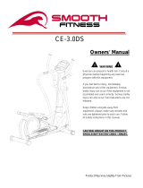
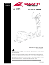
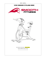
USER’S MANUAL
V390 Semi Recumbent Bike
USER WEIGHT LIMITATION: 300lbs(136kgs)
SERIAL NUMBER (found on frame):

2 V 390 SEMI-RECUMBENT BIKE
PRECAUTIONS
For future service or related questions:
Please staple your receipt and/or write in the name and phone number of the retail store where you purchased your bike.
Name: ______________________________ Phone Number: ___________________ Receipt: ______________________
Precautions:
WARNING: To reduce the risk of burns, fire, electric shock, or injury to persons, read the following important precautions
and information before operating the bike. It is the responsibility of the owner to ensure that all users of this bike are adequately
informed of all warnings and precautions.
• Use the bike only as described in this manual.
• Place on a level surface. Do not place the bike on any surface that blocks air openings. To protect the floor or carpet from
damage, place a mat under the bike.
• When choosing a location for the bike be sure that the location and position permit access to a plug.
• Keep the bike indoors, away from moisture and dust. Do not put the bike in a garage or covered patio, or near water.
• Do not operate the bike where aerosol products are used or where oxygen is being administered.
• Keep children under the age of 12 and pets away from the bike at all times.
• The bike should not be used by persons weighing more than 300LBS (136 Kgs).
• Never allow more than one person on the bike at a time. Wear appropriate exercise clothing when using the bike. Do not
wear loose clothing that could become caught in the bike. Athletic support clothes are recommended for both men and
women. Always wear athletic shoes. Never use the bike with bare feet, wearing only stockings, or in sandals.
• When connecting the power cord, plug the power cord into a grounded circuit.
• Always examine your bike before using to ensure all parts are in working order.
• Allow the bike to come to a full stop before stepping off.
• Never insert any object or body parts into any opening.
• Follow the safety information in regards to plugging in your bike.
• The item is suitable for semi-commercial, light-commercial and home usage.
• Keep the power cord away from the incline wheels and do not run the power cord underneath your bike. Do not operate
the bike with a damaged or frayed power cord.
• Always unplug the bike before cleaning and/or servicing. Service to your bike should only be performed by an authorized
service representative, unless authorized and/or instructed by the manufacturer. Failure to follow these instructions will
void the bike warranty.
Page is loading ...

4 V 390 SEMI-RECUMBENT BIKE
POWER REQUIREMENTS
Power Requirements:
IMPROPER CONNECTION OF THE EQUIPMENT GROUNDING CONNECTOR CAN RESULT IN THE RISK OF AN ELECTRIC
SHOCK. CHECK WITH A QUALIFIED ELECTRICIAN OR SERVICE MAN IF YOU ARE IN DOUBT AS TO WHETHER THE
PRODUCT IS PROPERLY GROUNDED. DO NOT MODIFY THE PLUG PROVIDED WITH THE PRODUCT, IF IT WILL NOT FIT
THE OUTLET; HAVE A PROPER OUTLET INSTALLED BY A QUALIFIED ELECTRICIAN.
This bike can be seriously damaged by sudden voltage changes in your home’s electrical power. Voltage spikes, surges and noise
interference can result from weather conditions or from other appliances being turned on or off. To reduce the possibility of bike
damage, always use a surge protector (not included) with your bike.
Surge protectors can be purchased at most hardware stores. The manufacturer recommends a single outlet surge protector with a
UL 1449 rating as a Transient Voltage Surge Suppressor (TVSS) with a UL suppressed voltage rating of 400V or less and an
electrical rating 120VAC, 15 amps.
This bike must be grounded to reduce the risk of electrical shock. Grounding provides a path of least resistance for electric current,
should the bike malfunction. This bike is equipped with an electrical cord that has an equipment-grounding conductor and a
grounding plug. Always plug the power cord into a surge protector, and plug the surge protector into an appropriate outlet that is
properly installed and grounded in accordance with all local codes and ordinances.
Alimentation :
UN MAUVAIS BRANCHEMENT DU CONNECTEUR DE MISE À LA TERRE DE L’ÉQUIPEMENT POURRAIT PROVOQUER UN
CHOC ÉLECTRIQUE. EN CAS DE DOUTE, CONSULTER UN ÉLECTRICIEN OU UN RÉPARATEUR QUALIFIÉ POUR SAVOIR
SI LE PRODUIT EST CORRECTEMENT MIS À LA TERRE. NE PAS MODIFIER LA FICHE FOURNIE AVEC LE PRODUIT. SI
ELLE N’ENTRE PAS DANS LA PRISE, FAIRE INSTALLER UNE PRISE APPROPRIÉE PAR UN ÉLECTRICIEN
PROFESSIONNEL.
Ce tapis roulant pourrait être gravement endommagé en cas de changement soudain de tension dans votre alimentation électrique.
Les conditions météorologiques ou la mise sous tension ou hors tension d’autres appareils électriques peuvent provoquer des
pointes de tension, des surtensions ou un brouillage. Pour réduire la possibilité que le tapis soit endommagé, toujours utiliser un
limiteur de surtension (non inclus) avec votre tapis roulant.
Il est possible d’acheter des limiteurs de surtension dans la plupart des quincailleries. Le fabricant recommande un limiteur de
surtension UL 1449 à prise unique comme suppresseur de tension transitoire (TVSS) ayant un taux de suppression de tension de
400 V ou moins et une tension électrique de 110 V C.A., 15 A.
Ce tapis roulant doit être mis à la terre pour réduire le risque de choc électrique. La mise à la terre fournit une voie de moindre
résistance au courant électrique en cas de mauvais fonctionnement du tapis roulant. Ce tapis roulant est équipé d’un cordon
électrique avec un conducteur de mise à la terre et une fiche de mise à la terre. Brancher toujours le cordon électrique dans un
limiteur de surtension et brancher le limiteur de surtension dans une prise appropriée, correctement installée et mise à la terre
conformément à tous les codes locaux et ordonnances.

www.smoothfitness.com
5
BEFORE YOU BEGIN
Open the boxes:
Open the boxes of your new equipment. Inventory all parts included in the boxes, and Supplied Hardware lists
on pages 7 for a full count of the parts included. If you are missing any parts or have any questions contact us
directly at 888-800-1167
Gather your tools:
Before you begin, make sure that you have gathered all the necessary tools you may require to assemble the unit
properly. Having all of the necessary equipment at hand will save time and make the assembly quick and hassle-free.
Clear your work area:
Make sure that you have cleared away a large enough space to properly assemble the unit. Make sure the space is
free from anything that may cause injury during assembly. After the unit is fully assembled, make sure there is a
comfortable amount of free area around the unit for unobstructed operation.
Invite a friend:
Some of the assembly steps may require heavy lifting. It is recommended that you obtain the assistance of another
person when assembling this product.
User Weight Limitation:
Please note that there is a weight limitation for this product. If you weigh more than 300LBS (Approx. 136 Kgs). It is
not recommended that you use this product. Serious injury may occur if the user’s weight exceeds the limit shown
here. This product is not intended to support users whose weight exceeds this limit.
Care and maintenance:
The safety level can be maintained only if it is examined for damage and wear.
Replace any defective components immediately and stop all use of the equipment until repaired.
Always take care when mounting the equipment. Straddle the equipment by placing your feet on the straddle rails.
Dismount from the equipment only after all parts have stopped.
Always check the wear and tear components like pulley, belts, etc.…To prevent injury.

6 V 390 SEMI-RECUMBENT BIKE
SUPPLIED COMPONENTS / SUPPLIED HARDWARE
This list identifies the major components you will use to assemble this product.
Console Upper Cover Console Bottom Cover Console Sleeve
Upright Post Assembly &
Water Bottle Bracket
Front Small Handlebar Upright Sleeve Seat Cushion
Mesh Backrest & Mesh
Backrest Cover
Rail Decoration Cover
Square Stopper,
Hex Head Bolt & Nut (M8)
Pedal Front Stabilizer
Seat Handlebar Assembly Seat Frame adjusting Handle Rear Stabilizer
Seat Carriage Assembly Main Frame Assembly & Leveler
Pull Bar & Fixed Bracket
for Seat Rail

www.smoothfitness.com
7
SUPPLIED COMPONENTS / SUPPLIED HARDWARE
This list identifies the major components you will use to assemble this product.
NOTICE:
The length of all bolts and screws except those with flat heads is
Measured from below the head to the end of the bolt or screw. Flat head
bolts and screws are measured from the top of the head to the end of
the
bolt or screw
After unpacking the unit, you will notice that the package includes 3 bags of hardware (HARDWARE KIT A,
HARDWARE KIT B and HARDWARE KIT C).
Assembly’s Step 1: Using HARDWARE KIT A
Assembly’s Step 2, 4: Using HARDWARE KIT B
Assembly’s Step 7 ~ 9: Using HARDWARE KIT C
Note:
a. Please review below to know the content of each hardware kit (A, B and C)
b. Some small parts may have been pre-attached for shipping. If a part is not in the hardware bag, check to see if it has
been pre-assembled
HARDWARE KIT A
Part No. and Description
Q’TY
88 Lock Washer (M8)
4 pcs
90 Washer (8x16x2.0t)
4 pcs
115 Bolt, Socket Head (M8xp1.25x90mm)
4 pcs
HARDWARE KIT B
Part No. and Description
Q’TY
88 Lock Washer (M8)
5 pcs
90 Washer (8x16x2.0t)
5 pcs
97 Screw, Pan Head (M5xp0.8x25mm)
4 pcs

8 V 390 SEMI-RECUMBENT BIKE
SUPPLIED COMPONENTS / SUPPLIED HARDWARE
This list identifies the major components you will use to assemble this product.
HARDWARE KIT B
Part No. and Description
Q’TY
99 Screw, Round Head (M5xp0.8x15mm)
4 pcs
111 Bolt, Socket Head (M6xp1.0x15mm)
112 Bolt, Socket Head (M8xp1.25x16mm)
114 Bolt, Socket Head (M8xp1.25x55mm)
4 pcs
4 pcs
1 pcs
HARDWARE KIT C
Part No. and Description
Q’TY
88 Lock Washer (M8)
10 pcs
90 Washer (8x16x2.0t)
10 pcs
93 Self-Tapping Screw, Truss Head (M4x16mm)
1 pc
99 Screw, Round Head (M5xp0.8x15mm)
2 pcs
107 Carriage Bolt (M8xp1.25x50mm)
2 pcs
112 Bolt, Socket Head (M8xp1.25x16mm)
113 Bolt, Socket Head (M8xp1.25x40mm)
10 pcs
4 pcs
119 Bolt, Hex Head (M10xp1.5x90mm)
1 pc
127 Nylock Nut (M8)
128 Thin Nylock Nut (M10xp1.5)
2 pcs
1 pc
THE FOLLOWING TOOLS ARE INCLUDED FOR ASSEMBLY:
MULTI WRENCH TOOL W/
PHILLIPS SCREWDRIVER
(13 & 15mm)
ALLEN WRENCH
(5 & 6 mm)
HEX WRENCH
(17mm x 2 pcs)

www.smoothfitness.com
9
COMPLETE PARTS LIST
NO.
Item Name
Q'TY
V390-1
Main Frame
1
V390-2
Front Seat Support Bracket
1
V390-3
Inner Seat Carriage Slider
1
V390-4
Outer Seat Carriage Slider
1
V390-5
Front Stabilizer
1
V390-6
Rear Stabilizer
1
V390-7
Upright Post
1
V390-8
Front Small Handlebar
1
V390-9
Seat Carriage
1
V390-10
Seat Fixed Stand
1
V390-11
Seat Frame
1
V390-12
Seat Handlebar
1
V390-13
Front Left Chain Cover
1
V390-14
Front Right Chain Cover
1
V390-15
Crank Cover (L&R)
2
V390-16
Rear Left Chain Cover
1
V390-17
Rear Right Chain Cover
1
V390-18
Decoration Cover for Carriage Slider
1
V390-19
Connection Cover
1
V390-20
Left Pedal
1
V390-21
Right Pedal
1
V390-22
Pulley
1
V390-23
Magnet
1
V390-24
Belt
1
V390-25
Pressure Wheel
1
V390-26
Bushing (
ψ
50.8x
ψ
10)
2
V390-27
Bushing (
ψ
60x
ψ
10)
4
V390-28
Slider Sleeve
1
V390-29
Pull Bar
1
V390-30
Tube Decoration Cover for Stabilizer
2
V390-31
Transprtation Wheel (L&R)
2
V390-32
Front Stabilizer End Cap
2
V390-33
Adjusting Rear Stabilizer End Cap
2
V390-34
Upright Sleeve
1
V390-35
Foam Grip (530mm)
2
V390-36
Square Plug (20x40mm)
1
V390-37
Console Upper Cover
1

10 V 390 SEMI-RECUMBENT BIKE
COMPLETE PARTS LIST
NO.
Item Name
Q'TY
V390-38
Console Bottom Cover
1
V390-39
Left Console Sleeve
1
V390-40
Right Console Sleeve
1
V390-41
Mesh Backrest
1
V390-42
Seat Cushion
1
V390-43
Foam Grip (330mm)
2
V390-44
Hand Pulse Sensor (L&R)
2
V390-45
Round Plug (31.8mm)
4
V390-46
Tube Plug (25.4mm)
4
V390-47
Locking Bar
1
V390-48
Left Seat Carriage Cover
1
V390-49
Right Seat Carriage Cover
1
V390-50
Adjusting Handle
1
V390-51
Seat Fixed Wheel
1
V390-52
Roller (37.6mm)
4
V390-53
Square Stopper
4
V390-54
Left Rail Decoration Cover
1
V390-55
Right Rail Decoration Cover
1
V390-56
Flywheel
1
V390-57
Cable
1
V390-58
Fixed Bracket for Motor
1
V390-59
Left Crank
1
V390-60
Right Crank
1
V390-61
Axle for Crank
1
V390-62
Fixed Bracket for Idler
1
V390-63
Upright Cover (L&R)
2
V390-64
Seat Rail
1
V390-65
Fixed Bracket for Seat Rail
1
V390-66
Adjusting Handle Stand
1
V390-68
Fixing Pin
1
V390-69
Axle for Sliding Track
1
V390-70
Axle for Braking
1
V390-71
Axle for Backrest Tube
1
V390-72
Bearing (6004zz)
2
V390-73
Eye Bolt (40mm)
2
V390-74
Eye Bolt (50mm)
3
V390-75
Tension Bracket
2

www.smoothfitness.com
11
COMPLETE PARTS LIST
NO.
Item Name
Q'TY
V390-76
Bushing (10.2x14x2mm)
1
V390-77
Bushing (10.2x14x10mm)
1
V390-78
Idler Spring
1
V390-79
Spring for Seat Fixed Stand
1
V390-80
Spring for Fixing Pin
1
V390-81
Spring for Adjusting Handle Stand
1
V390-82
Bushing for Seat Fixed Wheel
2
V390-83
Screw Cap
2
V390-84
Bushing (8x12x6.5mm)
4
V390-85
C Ring (20mm)
1
V390-86
Wave Washer
1
V390-88
Lock Washer (M8)
23
V390-89
Washer (6x19x1.5t)
2
V390-90
Washer (8x16x2.0t)
25
V390-91
Washer (10x23x2.0t)
3
V390-92
Washer (21x30x1.0t)
2
V390-93
Self-Tapping Screw, Truss Head (M4x16mm)
9
V390-94
Self-Tapping Screw, Truss Head (M5x18mm)
27
V390-95
Self-Tapping Screw, Flat Head (M4x20mm)
2
V390-96
Bolt, Button Head (M6xp1.0x40mm)
2
V390-97
Screw, Pan Head (M5xp0.8x25mm)
4
V390-98
Screw, Round Head (1/4’’x20mm)
4
V390-99
Nylon-Coated Screw, Round Head (M5xp0.8x15mm)
14
V390-100
Screw, Round Head (M5xp0.8x40mm)
2
V390-101
Bolt, Round Head (M6xp1.0x25mm)
8
V390-102
Bolt, Round Head (M6xp1.0x35mm)
2
V390-103
Bolt, Round Head (M6xp1.0x65mm)
1
V390-104
Screw, Flat Head (M5xp0.8x12mm)
4
V390-105
Bolt, Pan Head (M8xp1.25x15mm)
2
V390-106
Bolt, Pan Head (M8xp1.25x25mm)
4
V390-107
Carriage Bolt (M8xp1.25x50mm)
2
V390-108
Bolt, Button Head (M10xp1.25x35mm)
1
V390-109
Bolt, Hex Head (M10xp1.25x45mm)
1
V390-111
Bolt, Socket Head (M6xp1.0x15mm)
4
V390-112
Bolt, Socket Head (M8xp1.25x16mm)
14
V390-113
Bolt, Socket Head (M8xp1.25x40mm)
4
V390-114
Bolt, Socket Head (M8xp1.25x55mm)
1

12 V 390 SEMI-RECUMBENT BIKE
COMPLETE PARTS LIST
NO.
Item Name
Q'TY
V390-115
Bolt, Socket Head (M8xp1.25x90mm)
4
V390-116
Bolt, Hex Head (M8xp1.25x16mm)
4
V390-117
Bolt, Hex Head (M8xp1.25x105mm)
1
V390-118
Bolt, Hex Head (M8xp1.25x115mm)
2
V390-119
Bolt, Hex Head (M10xp1.5x90mm)
1
V390-120
Bolt, Hex Head (M10xp1.5x115mm)
2
V390-121
Collar Screw (M6)
2
V390-122
Flange Nut (M10)
2
V390-123
Nut (M6)
3
V390-124
Nut (M8)
4
V390-125
Nylock Nut (M6)
6
V390-126
Thin Nylock Nut (M8)
8
V390-127
Nylock Nut (M8)
9
V390-128
Thin Nylock Nut (M10xp1.5)
3
V390-129
Nylock Nut (M10xp1.25)
2
V390-130
Front Connection Wire
1
V390-131
Rear Connection Wire
1
V390-132
Adaptor Connection Wire w/ Nut
1
V390-133
Adaptor
1
V390-134
Sensor Wire w/Stand
1
V390-135
Motor w/ Wire
1
V390-136
Pulse Sensor Wire 1
1
V390-137
Pulse Sensor Wire 2
1
V390-138
Pulse Sensor Wire 3
1
V390-139
Short Extension Pulse Wire
1
V390-140
Pulse Sensor Wire 4
1
V390-141
Square Plug (25x75mm)
1
V390-142
Flange Nut – Black Color (M10)
2
V390-143
Nut (M5)
1
V390-144
Bolt, Button Head (M8xp1.25x16mm)
4
V390-145
Washer (8x26x2.0t)
2
V390-146
Self-Tapping Screw, Button Head (M4x16mm)
4
V390-147
Leveler
1
V390-148
Mesh Backrest Cover
1
V390-149
Lock Washer (M6)
4
V390-150
Water Bottle Bracket
1
V390-151
Bolt, Round Head M5x12mm
2

www.smoothfitness.com
13
PARTS DIAGRAM
MOST OF THE PARTS SHOWN HERE HAVE BEEN PRE-ASSEMBLED
Page is loading ...

www.smoothfitness.com
15
PARTS DISCRIPTION
Console
Front Small Handlebar
Mesh Backrest
Console Sleeve
Pulse
Sensor
Upright Post
Upright Sleeve
Adjusting
Handle
Main Frame
Front Stabilizer
Pedal
Seat Carriage
Assembly
Pull Pin
Rear Stabilizer
Water Bottle
Bracket

16 V 390 SEMI-RECUMBENT BIKE
ASSEMBLY
Step 1: Attach the Stabilizers, Leveler and Pedals
Note: the stabilizer is marked with an R to denote the right side.
Caution: Improperly rotating the pedal threads may cause damage to the equipment
A).Attach the front stabilizer to the main frame using 2x M8xp1.25x90mm Socket Head Bolts (115), 2 x M8 Lock
Washers (88) and 2 x 8x16x2.0t Washers (90). Slide the bolts through the front stabilizer and tread them in to the main
frame.
B). Attach the rear stabilizer to the main frame using 2x M8xp1.25x90mm Socket Head Bolts (115), 2 x M8 Lock
Washers (88) and 2 x 8x16x2.0t Washers (90). Slide the bolts through the rear stabilizer and tread them in to the main
frame.
C) Tilt the bike to the side and thread the leveler completely into the frame. You will adjust the leveler after assembly is
complete
D). Attach the right pedal into the right side crank. To tighten, turn the pedal treads clockwise.
E). Attach the left pedal to the left side crank. To tighten, turn the pedal threads counter clockwise
Be sure to thread the Leveler (147)
tightly into the Main Frame (1) before
moving to the next page
Tighten all bolts and fasteners now
USE HARDWARE KIT
A

www.smoothfitness.com
17
ASSEMBLY
STEP 2: Attach the Upright Post Assembly
Note: Do not tighten the upright post bolts until all four bolts are threaded into the post.
Caution: Do not pinch the wires between the frame
A). Slid the upright sleeve (34) on to the upright post assembly.
B). Attach the upright post assembly to the main frame using 4 x M8xp1.25x16mm socket head bolts (112), 4 x M8 lock
washers (88) and 4 x 8x16x2.0t washers(90).
C). Connect the Pulse Sensor Wire 3 (138) to the Pulse Sensor Wire 2 (137).
D). Connect the Rear Connection Wire (131C) to the Motor Wire (135).
E). Connect the Rear Connection Wire (131B) to the Sensor Wire (134).
F). Connect the Rear Connection Wire (131A) to the Adaptor Connection Wire (132).
G) Slide the upright post sleeve down until it attaches to the main frame covers.
Tighten all bolts and fasteners now
USE HARDWARE KIT
B

18 V 390 SEMI-RECUMBENT BIKE
ASSEMBLY
STEP 3: Attach the Console and Front Handlebar
Make sure all wires are recessed into the frame. DO NOT trap or pinch the wires.
A). Attach the console bottom cover (38) to the console upper cover (37) and secure using 4 x M5xp0.8x25mm pan
head screws (97). See Fig.1
B). Remove the 4 x bolts and washers from the front handlebar.
C). Slide the front handlebar through the upright post bracket. Secure the handlebar using 5 x M8xp1.25x16mm button
head bolts (114), 5 x M8 (88) and 5 x 8x16x2.0t washers (90) Tighten all bolts now,
NOTE: One Washer (8x16x2.0t)(90), one Lock Washer (M8)(88), one Bolt, Socket Head (M8xp1.25x45mm)(114) will
be packed into the hardware bag.
Tighten all bolts and fasteners now

www.smoothfitness.com
19
ASSEMBLY
STEP 4: Attach the Console Sleeve Assembly and Water Bottle bracket
A). Slide the console sleeve assembly (39) (40) around the upright post.
B) Be certain that the sleeve assembly aligns together properly and the lowest portion of the console bottom cover is
inside the console sleeve assembly.
C). Secure the two sleeves together using 4 x M5xp0.8x15mm round head screws (99)
D). Remove the pre-installed water bottle bracket screws from the console post
E). Line up the water bottle bracket with the upright post as pictured below.
F). Secure the bracket using the previously removed 2 x M5x12mm (151) round head bolts
USE HARDWARE KIT
B
Tuck the lowest
portion of the console
bottom cover under
the sleeve assembly’s
lip
Tighten all bolts and fasteners now

20 V 390 SEMI-RECUMBENT BIKE
ASSEMBLY
STEP 5: Attach the Inner Seat Carriage Slider
A). Insert the inner seat carriage slider (3) Into the main frame.
B) Slide the slider up to #5 and insert the pull pin in to the hole making sure the pan passes through the main frame
into the seat slider carriage.
C). Tighten the pull pin clockwise as much as possible.

www.smoothfitness.com
21
ASSEMBLY
STEP 7: Attach the Seat Rail and the Seat Carriage Assembly
A). Attach the fixed bracket (65) to the rear side of the seat carriage (9) and secure using 4 x M8xp1.25x16mm socket
head bolts (112), 4 x M8 (88) lock washers, and 4 x 8x16x2.0t washers (90).
B). Slide the seat carriage on to the main frame an insert the stopper bolt into hole one pictured below Fig. 3 (note the
stopper is preassembled to the bolt and nut)
C). Insert 2 x M8xp1.25x16mm socket head bolts (112), Lock Washers (M8)(88), and 2 x 8x16x2.0t washers (90)
through the left and right side of hole 2 pictured below Fig 2.
D) Secure the bottom of the front seat carriage to the main frame using 4 x M8xp1.25x16mm socket head bolts (112),
4 x M8 lock washers (88), and 4 x 8x16x2.0t washers (90) Fig. 3 & 4. Do not fully tighten until step 7 is completed.
E) Attach the rear of the seat carriage the inner seat carriage slider and secure using 1 x M10xp1.5x90mm hex head
bolt (119) and 1 x M10xp1.5 thin nylon lock nut (128) See fig. 5.
F) Tighten all bolts now
USE HARDWARE KIT
C
Fig. 2
Fig. 1
Fig. 3
Fig. 4
Fig. 5

22 V 390 SEMI-RECUMBENT BIKE
ASSEMBLY
STEP 8: Attach the pulse Sensor , Rail Cover Assembly and Adjuster Handle
A). Attach the Pulse Extension wire (139) in to the connector located on the front bottom side of the seat rail (64). See
fig. 2
B). Attach the left and right covers (54) (55) over the rear of the end of the seat rail.
C). Secure the rail covers together using 2 x M5xp0.8x15mm round head screws (99)and 1 x M4x16mm self-tapping
truss head screws (93)
D). Thread 1 x M8 nut (124) on the adjuster handle stand Fig. 3.
E).Thread the adjuster handle clock wise onto the adjuster handle stand (66) to the preferred position.
F). Turn the M8 nut counter clock wise to lock the adjuster handle in place.
USE HARDWARE KIT
C
Fig. 3
Page is loading ...
Page is loading ...
Page is loading ...
Page is loading ...
Page is loading ...
Page is loading ...
Page is loading ...
Page is loading ...
Page is loading ...
Page is loading ...
Page is loading ...
Page is loading ...
Page is loading ...
Page is loading ...
Page is loading ...
Page is loading ...
Page is loading ...
Page is loading ...
Page is loading ...
Page is loading ...
Page is loading ...
Page is loading ...
Page is loading ...
Page is loading ...
Page is loading ...
Page is loading ...
Page is loading ...
Page is loading ...
Page is loading ...
Page is loading ...
Page is loading ...
Page is loading ...
Page is loading ...
Page is loading ...
Page is loading ...
Page is loading ...
/