Page is loading ...

Kichler
®
Lighting
7711 East Pleasant Valley Road
P.O. Box 318010
Cleveland, Ohio 44131-8010
Customer Service
866.558.5706
8:30 AM to 5:00 PM EST,
Monday - Friday
Instruction Manual
Szeplo II
TM
A Kichler
®
Decor
™
ceiling fan
Includes wall mount
control system
300300,300301,300302
3066708

1. To reduce the risk of electric shock, insure
electricity has been turned off at the circuit
breaker or fuse box before beginning.
2. All wiring must be in accordance with the
National Electrical Code and local
electrical codes. Electrical installation
should be performed by a qualified
licensed electrician.
4. WARNING: To reduce the risk of personal
injury, use only the two steel screws (and
lock washers) provided with the outlet box
for mounting to the outlet box. Most outlet
boxes commonly used for the support of
lighting fixtures are not acceptable for fan
support and may need to be replaced,
consult a qualified electrician if in doubt.
5. WARNING: To reduce the risk of fire,
electric shock, or Personal Injury, mount
directly to a structural framing member or
to an outlet box marked 'Acceptable for
Fan Support of 15.9 kg (35 lbs) or less'. For
outlet box mounting, use mounting screws
provided with the outlet box.
6. The fan must be mounted with a minimum
of 7 feet clearance from the trailing edge of
the blades to the floor.
7. To operate the reverse function on this fan, press
the reverse button while the fan is running. A few
seconds later the fan will slow to a stop and then
reverse direction.
8. Avoid placing objects in the path of the blades.
9. To avoid personal injury or damage to the
fan and other items, be cautious when
working around or cleaning the fan.
10. Do not use water or detergents when
cleaning the fan or fan blades. A dry dust
cloth or lightly dampened cloth will be
suitable for most cleaning.
11. After making the electrical connections,
spliced conductors should be turned
upward and pushed carefully up into
outlet box. The wires should be spread
apart with the ground wire and white
(common) wire to one side with the black
(load) wire to the other side of the outlet
box.
12. Electrical diagrams are reference only.
Light kits that are not packed with the fan
must be ETL Listed and marked suitable
for use with the model fan you are
installing. Switches must be ETL General
Use Switches. Refer to the Instructions
packaged with the light kits and switches
for proper assembly.
WARNING
TO REDUCE THE RISK OF PERSONAL
INJURY, DO NOT BEND THE BLADE
BRACKETS (ALSO REFERRED TO AS
FLANGES) DURING ASSEMBLY OR AFTER
INSTALLATION. DO NOT INSERT OBJECTS
IN THE PATH OF THE BLADES.
1
1. SAFETY RULES
WARNING
To reduce the risk of fire, electric shock, or
Personal Injury, mount directly to a structural
framing member or to an outlet box marked
'Acceptable for Fan Support of 15.9 kg(35 lbs)
or less'. For outlet box mounting, use mounting
screws provided with the outlet box.
3. WARNING: To reduce the risk of fire or
electric shock, Use only the control
provided with the fan.

2
3. PACKAGE CONTENTS
Unpack your fan and check the contents .
You should have the following items:
A. Mounting bracket
B. Ball / downrod assembly
C.
Canopy
D.
Canopy Trim Ring
E. Coupling cover
F
. Motor Body
G. Blade Arm (6)
H. Blade (6)
I . Switch Housing
J. Led Assembly
K. Glass Shade
L. Steel Cap
M. Power Kit
N. Package Hardware
1) Mounting hardware:
wood screws (2), flat washers (2),
screws (2) , lock washers (2),
wire nuts (3)
2) Blade arm hardware :
screw (2)
3) Safety cable hardware :
wood screw (1) , spring washer (1),
flat washer (1)
4) Balance kit
5) Blade Mounting hardware:
8# screws (20), washers (20)
screw (3)
6) Screw hardware:
Philips screw driver
Blade screw driver
11 mm wrench
Step ladder
Wire cutters
2. TOOLS AND MATERIALS REQUIRED
Szeplo II
TM
A
B
C
E
D
F
H
G
I
J
M
N
K
L

4. MOUNTING OPTIONS
Outlet box
Provide strong
support
Recessed
outlet box
Ceiling
mounting
plate
Outlet box
Fig. 1
Fig. 3
Fig. 4
Outlet box
Fig. 2
ANGLED CEILING
MAXIMUM 30
°
ANGLE
3
If there isn't an existing ETL listed mounting
box, then read the following instructions.
Disconnect the power by removing fuses or
turning off circuit breakers.
Secure the outlet box directly to the building
structure. Use appropriate fasteners and
building materials. The outlet box and its
support must be able to fully support the
moving weight of the fan (at least 50 lbs). Do
not use plastic outlet boxes.
Figures 1, 2 and 3 are examples of different
ways to mount the outlet box.
NOTE: If you are installing the ceiling fan on a
sloped (vaulted) ceiling, you may need a
longer downrod to maintain proper clearance
between the tip of the blade and the ceiling.
A minimum clearance of 12" is suggested for
optimal operation.
NOTE: Depending on the location you have
selected for installation, you may need to
purchase and install a "Joist Hanger" for the
support of the outlet box. Make sure the joist
hanger you purchase has been designed for
use with ceiling fans. (Fig. 4)

4
5. HANGING THE FAN
REMEMBER to turn off the power before you
begin installation. This is necessary for your
safety and also the proper programming of the
control system.
To properly install your ceiling fan, follow the
steps below.
Step 1. Before attaching fan to outlet box
(not included), ensure the outlet box is securely
fastened to at least two points to a structural
ceiling member (a loose box will cause the fan
to wobble). Pass the 120 volt supply wires from
the ceiling outlet box through the center of the
ceiling mounting bracket. Install mounting
bracket to outlet box in ceiling using the screws
and washers included with the outlet box or
screws and washers in the hardware bag.
(Fig. 5)
Step 4. Slip the coupling cover, canopy trim ring
and canopy onto the downrod. Carefully reinstall
the hanger ball onto the downrod . Make sure the
cross pin is in the correct position and the set
screws are tight and the wires are not twisted .
( Fig. 8)
Step 2. Remove the hanger ball from downrod
assembly by loosening set screws , removing
the cross pin, and twisting ball out of the rod.
( Fig. 6)
Step 3. Loosen the two set screws and remove
the clip and cross pin from the top coupling of
the motor body.
Carefully feed the fan wires up through the
downrod. Thread the downrod onto the motor
coupling until the cross pin holes are aligned.
Next, replace the cross pin and clip, and tighten
both set screws. (Fig. 7)
Flat Washer
Screw
Fig. 5
Ceiling Mounting Bracket
ETL Listed Outlet Box
Screw
Downrod
Cross Pin
Fig. 6
Set Screw
Hanger Ball
Fig. 7
Fig. 8
Szeplo II
TM
Motor Body
Cross Pin
Clip
Set Screw
Hanger Ball
Canopy
Canopy Trim Ring
Coupling Cover
Motor Body

5
Step 5. Now lift the motor body into position
and place the hanger ball into the hanger bracket.
Rotate until the "Check Tab" has dropped into
the "Registration Slot " and seats firmly. ( Fig. 9)
The entire motor body should not rotate is this is
done correctly.
6 . INSTALLATION OF SAFETY SUPPORT
(required for Canadian installation ONLY)
WARNING: Failure to properly seat the "Check
Tab" can damage the ceiling fan during operation.
A safety support cable is provided to help prevent
the ceiling fan from failing, please install it as
follows.
Step 1. Drive a wood screw and washers into the
side of the brace that holds the outlet box. Leave
3mm (1/8") of space between the support brace
and the washer. (Fig. 10)
NOTE: Although the safety support cable is
required for Canadian installations only. It’s a good
idea to make the attachment with any installation.
Step 2. Insert the safety cable through the
mounting bracket and one of the holes in the
outlet box into the ceiling. Adjust the length of the
safety cable to reach the screw and washers by
pulling the extra cable through the cable clamp
until the overall lenght is correct, put the end of the
cable back through the cabel clamp, forming a
loop at the end of the cable. Tighten the cable
clamp securely. Now, put the loop in the end of the
safety cabel over the wood screw and under the
washer. Tighten the wood screw securely. (Fig. 11)
Safety Cable
Bolt
Wood Screw
Fig. 11
Fig. 10
Flat Washer
Wood Screw
Spring Washer
Outlet Box
Support Brace
Ceiling
Fig. 9
Hanger Ball
Check Tab
Registration Slot

6
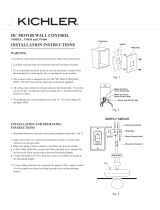
7. HOW TO WIRE YOUR CEILING FAN
8. INSTALLATION OF THE CANOPY
Step 1. Remove one of the two shoulder screws
in the mounting bracket. Loose the second
shoulder screw without fully removing it. (Fig. 14)
Step 2. Assembly canopy by rotating key slot in
canopy over shoulder screw in mounting bracket.
Tighten shoulder screw. Fully assembled and
tighten second shoulder screw that was previously
removed. (Fig. 15)
Fig. 14
Fig. 13
Fig. 12
Fig. 15
Mounting Bracket
Shoulder Screw
Green (ground) Wire
Black Wire
White Wire
Green Wires
Black Wire
White Wire
If you feel that you do not have enough electrical
wiring knowledge or experience, have your fan
installed by a licensed electricial.
Warning: To avoid possible electrical shock, be
sure electricity is turned off at the main fuse box
before wiring.
Note: If you are not sure if the outlet box is
grounded, contact a license electricial for advice,
as it must be grounded for safe operation.
Step 1. Connect the GREEN grounding leads
to the grounding conductor of supply (this may
be a bare wire or wire with green colored insulation).
Securely connect wires with wire connector
supplied. (Fig. 12)
Step 2. Securely connect the fan WHITE wire to
the supply WHITE wire using wire connector
supplied. Securely connect the fan BLACK wire
to the supply BLACK wire using wire connector
supplied. (Fig. 12)
Step 3. After connections have been made, turn
leads upward and carefully push leads into the
outlet box, with the white and green leads on
one side of the outlet box and position
the black leads on the other side of the oulet box.
(Fig. 13)
Canopy
Shoulder Screw
Szeplo II
TM

7
NOTE: Before continuing, make sure the power
is disconnected by turning off the circuit breaker
of removing the fuse at the circuit box.
Step 1. Position the blade over the blade arm
with threaded posts showing. Make sure the
bottom edge of the blade is fully seated against
the blade arm. With a Philips screwdrivr, start
a screw into the blade arm (do not tighten)
and repeat for the 2 remaining blade screws
and washers. Tighten each screw securely
starting with the center screw. Make sure the
blade is straight. Repeat steps for the
remaining blades. (Fig. 17)
Step 2. Remove and discard the three stabilizers
tabs and screws. Faster blade assembly to the
holes located on the bottom of the flywheel.
Tighten the two "pre- installed" motor screws
in the blade arm. Repeat steps for the remaining
blades assemblies. (Fig. 18)
9. ATTACHING THE FAN BLADES
Fig. 17
Fig. 18
Step 3. Securely attach and tighten the canopy
trim ring over the shoulder screws in the mounting
bracket utilizing the keyslot twist-lock feature.
(Fig. 16)
Fig. 16
Canopy Trim Ring
Blade Screw
Blade
Blade Arm
Washer
Shipping Block
Screw
Blade Assembly
Blade Arm Screw
Motor Body

8
11. INSTALLING THE LED ASSEMBLY OR CAP
NOTE: Before continuing, make sure the power
is disconnected by turning off the circuit breaker
of removing the fuse at the circuit box.
Step 1. If installing with steel cap and no light
kit, skip to step 4 on page 9. Remove one of
the three screws in the switch housing.
Retain the screw for later and slightly
loosen the remaining two screws. (Fig. 20)
Step 2. Connect the 2 single pin connectors
from the LED assembly to the 2 single pin
connectors from motor assembly,
BLACK to BLACK, WHITE to WHITE.
Assemble the LED assembly to the switch
housing using the two key slots. Replace the
removed screw and secure all three screws.
(Fig. 21)
Fig. 20
Fig. 21
Step 1. Remove one of the three screws and
loosen the other two (do not remove). Place the
two slot holes on the switch housing over the 2
screws previously loosened from the mounting
ring. Rotate the switch housing until it locks in
place at the narrow end of the key holes.
Securely by tightening the 2 screws previously
loosened and the one previously removed.
(Fig. 19)
10. INSTALLING THE MOUNTING PLATE
Fig. 19
Switch Housing
Screw
Mounting Plate
Switch Housing
Screw
LED Assembly
Screw
Switch Housing
Szeplo II
TM

9
Fig. 24
12. WALL CONTROL INSTALLATION
NOTE: Make all wiring conenctions using wire
connectors (supplied). Make sure that all
connections are tight, including ground, and that
no bare wire is visible at the wire connectors,
except for the ground wire.
Step 1. Remove faceplate and screws from
existing wall control (if present). Pull control out
from the wall box. Determine the "hot" wire and
"load" wire and disconnect these wires from
control (Fig. 24). Do not attempt to disconnect any
wires not already connected to existing control.
Caution: To reduce the risk of electrical shock,
disconnect the electrical supply circuit before
installing the fan, light kit or receiver.
Step 4. If you want to install the steel cap and
not the light kit. Assemble the steel cap to the
switch housing by twisting in a clockwise
direction. (Fig. 23)
Step 3. Secure the glass shade to switch
housing by twisting in a clockwise direction.
Do not over-tighten. (Fig. 22)
HOT
BLK
BLACK
BLACK
LOAD
GROUND
NEUTRAL
Switch Housing
Steel Cap
Fig. 22
Fig. 23
Switch Housing
Glass Shade

10
Step 3. Try different speed setting on wall control
to ensure the fan is now fully functional.
If programming is unsuccessful, retry the process
starting from step 1 agains.
Step 2. The fan will run for approximately 2 minutes
in the upware direction then reverse direction to
down flow and run an additional 2 minutes. When
conditioning is complete, the fan will come to complete
stop and light will blink (if there is a light on the fan).
The fan is now ready for normal use.
IMPORTANT: Do not interrupt the conditioning
until the fan comes to a complete stop in
approximately 5 minutes. All functions of the
control will be rejected during conditioning.
13. PAIRING PROCEDURES
IMPORTANT: Ceiling fan blades MUST be
installed before paring procedure can begin.
Step 1. Turn the wall control to "OFF" postion.
Restore electricity to the ceiling fan branch circuit
at the circuit breaker or fuse box. Within 60
seconds of press the" "switch to "ON" and then
hold the" "button fro 3 to 5 seconds.
Step 2. Before installing the wall control, place it
in "OFF" mode by press the button. (higher than
faceplate).
Step 3. Connect one black wire of wall control to
the "hot" wire (house source). Securely connect
wires with wire connectors supplied. (Fig. 25)
Step 4. Connect another black wire of wall control
to the "load" (black) wire in the wall box. Securly
connect wires with wire connector supplied.
Fig. 25
BLK
BLACK
GROUND
TO LOAD
HOT
TO 120V SOURCE
Szeplo II
TM

Problem
Fan will not start.
Fan sounds noisy.
Fan wobble.
Remote control
malfunction.
Solution
1. Check circuit fuses or breakers.
2. Check all electrical connections to insure proper contact. CAUTION: Make
sure the main power is OFF when checking any electrical connection.
3. Make sure the transmitter batteries are installed properly. Positive (+) side
facing out.
4. Insure the batteries have a good charge.
1. Make sure all motor housing screws are snug.
2. Make sure the screws that attach the fan blade brackets to the motor are
tight.
3. Make sure wire nut connections are not rubbing against each other or the
interior wall of the switch housing. CAUTION: Make sure main power is off.
4. Allow a 24-hour "breaking-in" period. Most noise associated with a new fan
disappear during this time.
5. If using an optional light kit, make sure the screws securing the glassware are
tight. Make sure the light bulbs are not touching any other component.
6. Do not connect this fan to a wall mounted variable speed control(s). They are
not compatible with ceiling fan motors or remote controls.
7. Make sure the upper canopy is a short distance from the ceiling. It should not
touch the ceiling.
1. Check that all blade and blade arm screws are secure.
2. Most fan wobbling problems are caused when blade levels are unequal.
Check this level by selecting a point on the ceiling above the tip of one of the
blades. Measure this distance. Rotate the fan until the next blade is positioned
for measurement. Repeat for each blade. The distance deviation should be
equal within 1/8".
3. Use the enclosed Blade Balancing Kit if the blade wobble is still noticeable.
4. If the blade wobble is still noticeable, interchanging two adjacent (side by
side) blades can redistribute the weight and possibly result in smoother
operation.
1. Ceiling Fans with remote control systems CAN NOT be operated in
conjunction with any other control system EXCEPT a basic On/Off wall switch,
if desired.
15. TROUBLESHOOTING
11
14. USING YOUR CEILING FAN
Press the" "button once to turn ON (or OFF) the
fan. (Fig. 26)
If airflow is desired in the opposition direction,
press the" "button. The fan must be operating at
any speed for the reverse button to function. The
blades will turn in the opposite direction and
reverse the airflow. (Fig. 26)
Fig. 26
To turn the light on and off, press and release the
light" "button. To set the light intensity, press and
hold the light button. The light will turn on at the
light intensity previously selected. (Fig. 26)
To set the desired fan speed, press and hold the" "
button to decrease and increase the speed. (Fig. 26)
Light Button
Fan Speed Button
Airflow Direction
Power Button
Indication Light
(Power)

This device complies with part 15 of the FCC Rules. Operation is subject to the following
two conditions:
(1) This device may not cause harmful interference, and (2) this device must accept any interference
received, including interference that may cause undesired operation.
Changes or modifictions not expressly approved by the party responsible for compliance could void
the user's authority to operate the equipment.
NOTE: This equipment has been tested and found to comply with the limits for a Class B digital device,
pursuant to part 15 of the FCC Rules. These limits are designed to provide reasonable protection against
harmful interference in a residential installatio. This equipment generates, uses and can rediate radio
frequency energy and, if not installed and used in accordance with the instructions, may cause harmful
interference to radio communications. However, there is no guarantee that interference will not occur in
a particular installation. If this equipment does cause harmful interfenence to radio or television reception,
which can be determined by turning the equipment off and on, the user is encouraged to try to correct the
interference by one or more of the following measures:
Reorient or relocate teh receiving antenna, increase the separation between the equipment and receiver,
and connect the equipment into an outlet on a circuit different from that no which the fan is connected.
These are approximate measures. They do not included data for any lamps or fixtures attached to the
ceiling fan.
16. FCC WARNNING:
17. SPECIFICATIONS:
12
12.9kgs 14.3kgs 2.02’
14.6kgs 16.2kgs 2.55’
15.7kgs 17.6kgs 3.10’
N.W. G.W. C.F.RPM
138~141
111~116
98~101
CFM
7846
6488
5696
CFM/W
251
369
550
Fan Size
60"
(300300)
(300301)
(300302)
120
120
120
Volts
0.3936
0.234
0.161
Amps
31
18
10
WattsSpeed
96"
5
4
3 0.124
2
1
6
5
4
3
2
1
0.081
0.051
7
4
3
79~83
64~67
48~52
4881
3870
3039
710
900
1203
89~92
77~80
65~68
11399
9840
8386
360
494
638
0.401
0.268
0.183
32
20
13
0.146
0.090
0.069
8
5
4
53~56
41~44
29~31
7037
5361
4138
840
1096
1169
6
5
4
3
2
1
60~63
51~54
43~46
12854
11395
9710
419
658
852
0.390
0.234
0.167
31
17
11
0.129
0.081
0.047
7
4
3
35~38
27~29
19~21
7994
6199
4614
1098
1435
1831
80"
/