WINGBO WBCF-Q008-NI User manual
- Category
- Household fans
- Type
- User manual
This manual is also suitable for

CEILING FAN
Instruction Manual
Read Completely Before Installation
& Use and Keep for Future Reference

1
TABLE OF CONTENTS
INTRODUCTION
Introduction ··································································································· 1
Package Contents ·························································································· 2
Safety Information··························································································· 3
Preparation ··································································································· 4
Initial Installation ···························································································· 5
Circuit Connections ························································································ 6
Host Installation ····························································································· 7
Fan Blade Installation ······················································································ 7
Light Plate Installation ····················································································· 8
LED Light Kit Installation ·················································································· 8
Lamp Shade Installation ·················································································· 9
Host Testing ·································································································· 9
Color Temperature Adjustment ·········································································· 9
Remote Control Operation ·············································································· 10
Troubleshooting ····························································································11
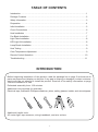
Before beginning installation of this product, read the package list on page 2 and ensure all
parts are present and display no defects. If any part is missing or damaged, contact customer
service and do not attempt to install the product. Read all of the safety information on page
3 before installation or use.
Estimated assembly time: 120 minutes
Additional tools required for assembly:
Electrical tape, flathead & Phillips screwdriver, pliers, safety glasses, ladder, and wire strippers
Additional helpful tools:
AC tester light, tape measure, wiring handbook, and wire cutters

2
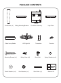
PACKAGE CONTENTS
Fan Blades (×4) Fan Motor Assembly Light Plate
LED Light Kit
Glass Lamp Shade Transmitter
Receiver
MED
HILOW
STOP
2H
4H
1H
R/F
LI
Ceiling Mounting Bracket
Mounting Screws (×4) Wiring Caps (×8) Spring Washers (×4)
Metal Washers (×4) Star Washers (×4) Short Bolts (×2) Balance Kit
Short Bolt

3
1. To reduce the risk of electric shock, ensure electricity has been turned off at the circuit
breaker or fuse box before beginning.
2. All wiring must be in accordance with national and local electrical codes. Electrical
installation should be performed by a qualified licensed electrician.
3. This fan is suitable for use with solid-state speed controls.
4. To reduce the risk of personal injury, use only the screws and washers provided with
the outlet box for mounting to the outlet box. Most outlet boxes commonly used for
the support of lighting fixtures are not acceptable for fan support and may need to be
replaced. Consult a qualified electrician if in doubt.
5. The outlet box and support structure MUST be securely mounted and capable of reliably
supporting a minimum of 50 pounds. Use only UL listed outlet boxes marked "FOR
FAN SUPPORT".
6. After marking electrical connections, spliced conductors should be turned upward and
pushed carefully up into outlet box. The wires should be spread apart with the grounded
conductor and the equipment-grounding conductor on one side of the outlet box.
7. The fan must be mounted with a minimum of 7 feet clearance from the trailing edge of
the blades to the floor.
8. Do not use the reverse switch while the fan blades are in motion. To prevent damage
and ensure long use, the fan must be turned off and the blades stopped before
reversing direction.
9. Do not place objects in the path of the blades.
10. Exercise caution when working around or cleaning the fan.
11. Use a soft dry cloth to clean the fan body and blades. Do not use water or detergent.
12. The electrical diagrams provided herein are for reference only. Light kits that are not
packaged with the fan must be UL listed and suitable for use with this fan. Switches must
be UL general use switches. Refer to their separate instructions for proper assembly.
TO REDUCE THE RISK OF FIRE, ELECTRIC SHOCK, & PERSONAL INJURY,
MOUNT FAN TO AN OUTLET BOX MARKED “ACCEPTABLE FOR FAN SUPPORT”.
SAFETY INFORMATION
Warning!
NEVER BEND THE BLADE BRACKETS/FLANGES FOR ANY REASON.

4
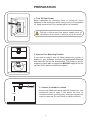
PREPAR ATION
1. Turn Off Your Power
Begin installation by removing fuses or turning off circuit
breakers to the wiring you will be using. Use your compatible
UL listed junction box if you already have one installed.
2. Choose Your Mounting Position
If you need to install a new UL listed junction box, secure it
directly to your building's structure usingappropriate fasteners
and materials. Do not use plastic boxes. The outlet box and its
supports must be able to support the MOVING weight of the fan
(at least 50 lb.) and be rated for fan support.
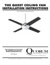
3. Choose a Suitable Location
Ensure the blades will be at least 30 inches from any
obstruction and at least 7 feet above the floor. In
locations without a ceiling joist, a hanger support bar
may be required. Do not install in damp locations.
Failure to disconnect the power supply prior to
installation may result in serious injury or death.
7 feet
30 inches
Use only on flat ceilings
Do not use on slanted surfaces

5
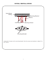
Loosen the 4 screws on the mounting bracket Use the screws and washers to attach it to
your ceiling.
INITIAL INSTALLATION
Mounting Bracket
Washer
Mounting Screws
120V Wires
Solid Wood
Ceiling
Mounting Bracket

6
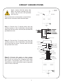
CIRCUIT CONNECTIONS
Receiver
Steel Wire
Mounting
Bracket
White (neutral)
Green or Bare
Copper (ground)
White (“AC IN N”)
Outlet Box
Black (hot)
Black (“AC IN L”)
White (neutral)
Blue (light)
Green (ground)
White (neutral)
Black (motor)
Blue (light)
Red (for L)
Receiver
Red (for L)
Orange
(for N)
Black (“to motor L”)
Orange (for N)
Receiver Head
GREY
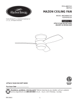
Ensure there are no loose wires or connections,
and secure connectors with electrical tape.
Step 2: Connect the 2 colored wires from the
remote receiver to the 2 identically colored lead
wires from the fan motor. Secure each set with
the provided wire nuts.
Step 3: Connect the green or bare copper
ground wire from the outlet box to the ground
wires from the ceiling fan. Separate the white
and green connections from the black wire
connections, which should be kept on opposite
sides of the outlet box.
Again, ensure that the power has
been cut before working with the
wiring. Use the wire nuts provided
with your fan.
Step 1: Connect the 5 colored wires from the
remote receiver to the 5 identically colored lead
wires from the fan motor. Secure each set with the
provided wire nuts.

7
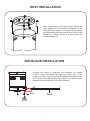
HOST INSTALLATION
FAN BLADE INSTALLATION
After confirming the wiring is correct, install the
main engine onto the mounting bracket. First,
hang the main engine to the mounting bracket
by sliding its slots onto the built-in bolts of the
bracket (1). Then, secure it in place with the
provided bolts (2).
Loosen the bolts & washers pre-installed on blade
holder. Insert the blade through the blade slot in the
motor housing. Align the holes on blade and blade holder
and use the provided washers and bolts to connect them.
Repeat this process with the other blades.
blade
screw
S
Loosen the screws & fiber washers pre-installed on blade holder;
and then insert the blade through the blade slot in the motor housing.
Align the holes on blade and blade holder, making sure the holes are
secured with the screws & washers provided. Repeat this process
with the other blades.
After ensuring the line connection is accurate, install
the main engine on the hanging tray.
Please hide the circuit in the bell on the main
engine, so as to avoid electric leakage. Tighten the
two ears of the clock against the screws on the wall,
then tighten the other two screws and tighten all the
rest screws.
Blade
Bolt
1
2

8
Loosen the screws & fiber washers pre-installed on blade holder;
and then insert the blade through the blade slot in the motor housing.
Align the holes on blade and blade holder, making sure the holes are
with the screws & washers provided. Repeat this process
After ensuring the line connection is accurate, install
engine, so as to avoid electric leakage. Tighten the
two ears of the clock against the screws on the wall,
then tighten the other two screws and tighten all the
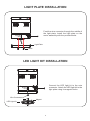
LIGHT PLATE INSTALLATION
LED LIGHT KIT INSTALLATION
Feed the wire connector through the middle of
the light plate. Install the light plate on the
motor assembly with the provided bolts.
Connect the LED light kit to the wire
connector. Attach the LED light kit to the
light plate using its magnetic bolts.
Light Plate
Bolts
Wire Connectors
LED Light Kit
Magnet

9
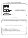
LIGHT PLATE INSTALLATION
COLOR TEMPERATURE ADJUSTMENT
The LED light has 3 different color setting: Warm White (3000K), Daylight (4500K), and
Cool White (6000K). To adjust the light settings,
1. Press LIGHT on the remote control to turn on the LED light.
2. Press and hold the the LIGHT button until the LED light turns off.
3. Press and hold the the LIGHT button until the LED light turns on again with the next
color temperature in order.
Repeat these steps to cycle through the 3 color temperatures.
HOST TESTING
Turn on the power and press the LIGHT key on the remote control to test whether the fan
is powered or not. Test each fan speed. If there are any problems, disconnect the fan from its
power supply and correct the wiring.
Light Plate
Glass Shade
Install the glass lamp shade onto the light
plate, turning it into place. Ensure it is
firmly connected to avoid loosening during
use.

10
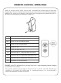
REMOTE CONTROL OPERATION
Install the remote control holder onto any wall or suitable flat surface using the two steel
screws. Upon first use, connect the remote control to its receiver in the fan by pressing LI
and HI on the emitter until a beep is heard (Note that this programming cannot be done for
the first 30 seconds after the receiver is turned on.)
DO NOT press F/R while the fan is turning. Wait for it to stop completely before changing
the direction of its rotation.
This remote operates with a range of 30 feet (10 m). It uses 2 1.5V AAA batteries (not
included). If the remote will not be used for a prolonged period, it is recommended to
remove the batteries for better service life.
Starts the fan at low speed
Starts the fan at medium speed
Starts the fan at high speed
Stops the fan
Turns the light on or off
Runs the fan for 1 hour and then turns it off
Runs the fan for 2 hours and then turns it off
Runs the fan for 4 hours and then turns it off
Reverses the fan’s direction
Key Function
Low
MED
HI
STOP
LIGHT
1H
2H
4H
F/R

11
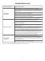
TROUBLESHOOTING
Potential Problems
Fan blades
don't rotate
Fan is too noisy
Fan wobbles
during use
Common Solutions
Check fuses and/or circuit breakers and reset if needed.
Cut off power to the fan and check its internal electrical
connections.
Replace the remote control’s batteries.
Check that the fan cover is correctly placed and no screws
interfere with the movement of the blades.
Contact customer service to replace a faulty remote control.
Check that all screws and fasteners are well tightened.
Ensure the canopy housing has a short distance between
itself and the ceiling.
Upon initial installation, allow 24 hours of use for the machine
to break itself in.
Cut off power to the fan and check that the wire nut connections
are not rubbing against one another or the inner housing.
If you have installed a solid-state variable-speed control, cut
off power to the fan and disconnect this control from the
device. See if using the remote resolves the problem, which
can be caused by erratic signals from such controls.
Check that all screws and fasteners are well tightened.
Use the provided blade balancing kit to adjust the blades if
their tips are found to be an unequal distance from the ceiling
while well fastened.
Exchange the position of the various blades.
Again, do not bend the blades during any of these procedures.
-
 1
1
-
 2
2
-
 3
3
-
 4
4
-
 5
5
-
 6
6
-
 7
7
-
 8
8
-
 9
9
-
 10
10
-
 11
11
-
 12
12


WINGBO WBCF-Q008-NI User manual
- Category
- Household fans
- Type
- User manual
- This manual is also suitable for
Ask a question and I''ll find the answer in the document
Finding information in a document is now easier with AI
Other documents
-
Atlas IR3HLK-CR-WA-42 Operating instructions
-
Home Decorators Collection YG446-BN Operating instructions
-
-
 Quorum Quest Operating instructions
-
-
 Harbor Breeze MZ44WW3LR Installation guide
-
 Harbor Breeze MZ44MBK3LR User manual
-
-
-


