Page is loading ...

Español p. 21
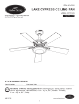
ITEM #0396794
MODEL #LP8073LAZ
BAJA II CEILING FAN
ATTACH YOUR RECEIPT HERE
Serial Number
Purchase Date
Lowes.com/harborbreeze
Questions, problems, missing parts? Before returning to your retailer, call our customer
service department at 1-800-643-0067, 8 a.m. - 6 p.m., EST, Monday - Thursday and
8 a.m. - 5 p.m., EST, Friday.
Harbor Breeze® is a registered trademark
of LF, LLC. All Rights Reserved.
1
EB13232

Lowes.com/harborbreeze
TABLE OF CONTENTS
Package Contents .........................................................................................................................
Hardware Contents .......................................................................................................................
Safety Information .........................................................................................................................
Preparation ...................................................................................................................................
Assembly Instructions ...................................................................................................................
Wiring Instructions ........................................................................................................................
Final Assembly Instructions ..........................................................................................................
Operating Instructions ..................................................................................................................
Blade Balancing Instructions ........................................................................................................
Care and Maintenance .................................................................................................................
Troubleshooting ............................................................................................................................
Warranty .......................................................................................................................................
Replacement Parts List ................................................................................................................
3
4
4
5
6
10
11
15
16
17
17
19
20
2

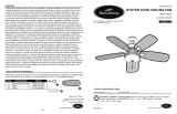
PART DESCRIPTION QUANTITY
A Motor Assembly 1
B
Hanger Bracket
1
C
Downrod
D
Ceiling Canopy
1
E
Canopy Screw Cover
1
F
Motor Coupling Cover
1
G
Switch Housing Assembly
1
H Blade Arm 5
PART DESCRIPTION QUANTITY
F
G
H
I
1
B
C
D
E
A
Lowes.com/harborbreeze
I
Blade 5
PACKAGE CONTENTS
3

SAFETY INFORMATION
Please read and understand this entire manual before attempting to assemble, operate or install
the product.
Before you begin installing the fan, disconnect the power by removing fuses or turning off circuit
breakers.
Make sure all electrical connections comply with local codes, ordinances, or the National Electrical
code. Hire a qualified electrician or consult a do-it-yourself wiring handbook if you are unfamiliar
with installing electrical wiring.
Make sure the installation site you choose allows a minimum clearance of 7 ft. from the blades
to the floor and at least 30 in. from the ends of the blades to any obstruction.
If you are mounting the fan to a ceiling outlet box, use a METAL octagonal outlet box.
Secure the box directly to the building structure. The outlet box and its support must be able to
support the moving weight of the fan (at least 35 lbs.). Do NOT use a plastic outlet box.
After you install the fan, make sure all connections are secure to prevent the fan from falling.
For supply connections, if the conductor of a fan is identified as a grounded conductor, then it
should be connected to a grounded conductor power supply. If the conductor of a fan is identified
as an ungrounded conductor, then it should be connected to an ungrounded conductor power
supply. If the conductor of a fan is identified for equipment grounding, then it should be connected
to an equipment-grounding conductor.
The net weight of this fan is: 22.27 lbs.
HARDWARE CONTENTS (shown actual size)
Wire
Connector
Qty. 4
DD
Screw
Qty. 11
AA
Fiber
Washer
Qty. 11
CC
BB
Washer-Head
Screw
Qty. 11
Lowes.com/harborbreeze
Balance
Kit
(not shown
to size)
Qty. 1
FFEE
Fan Chain
Coupler
(not shown
to size)
Qty. 1
4

SAFETY INFORMATION
Lowes.com/harborbreeze
Before beginning assembly of product, make sure all parts are present. Compare parts with
package contents list and hardware contents list. If any part is missing or damaged, do not
attempt to assemble the product.
Estimated Assembly Time: 60 minutes
Tools Required for Assembly (not included): Phillips screwdriver, 1/4 in. flathead screwdriver,
wire stripper and step ladder.
Helpful Tools (not included):AC tester light, do-it-yourself wiring handbook and wire cutters.
PREPARATION
WARNING
'RQRWLQVWDOORUXVHIDQLIDQ\SDUWLVGDPDJHGRUPLVVLQJ
7RUHGXFHWKHULVNRIILUHHOHFWULFDOVKRFNRUSHUVRQDOLQMXU\ZLUHFRQQHFWRUVSURYLGHGZLWKWKLV
fan are designed to accept only one 12-gauge house wire and two lead wires from the fan. If
your house wire is larger than 12-gauge or there is more than one house wire to connect to the
two fan lead wires, consult an electrician for the proper size wire connectors to use. Before
cutting, drilling or hammering, verify their location. If needed, contact your electrician, plumber
or service person.
To reduce the risk of fire, electric shock, or personal injury, do not bend the blade arms when
installing them, balancing the blades, or cleaning the fan. Do not insert foreign objects between
the rotating fan blades. Mount to outlet box marked “ACCEPTABLE FOR FAN SUPPORT” and
use mounting screws provided with the outlet box. Most outlet boxes commonly used for the
support of lighting fixtures are not acceptable for fan support and may need to be replaced.
Consult a qualified electrician if in doubt.
This fan is to be used in dry or damp locations.
5HDGDOOLQVWUXFWLRQVDQGVDIHW\LQIRUPDWLRQEHIRUHLQVWDOOLQJWKHQHZIDQ5HYLHZDFFRPSDQ\LQJ
assembly diagrams.
CAUTION
5

C
ASSEMBLY INSTRUCTIONS
C
A
Lowes.com/harborbreeze
C
1
2
3
1. Remove the hanger ball portion from the
downrod (C) by loosening the preassembled
set screw in the hanger ball until the ball falls
freely down the downrod (C). Remove the
preassembled pin from the downrod (C), then
remove the hanger ball. Retain the pin and
hanger ball for later.
2. Remove the preassembled hairpin clip and
clevis pin from the bottom of downrod (C).
Retain the pin and clip for later.
3. Loosen the two preassembled set screws in
the downrod support of the motor assembly
(A). Route the black white and blue wires
through the downrod (C).
6

ASSEMBLY INSTRUCTIONS
C
Lowes.com/harborbreeze
D
E
F
5
6
4. Thread the downrod (C) into downrod support
of the motor assembly (A). Align the holes in
the downrod support of the motor assembly (A)
with the holes in the downrod (C) and install the
previously removed clevis pin. Secure clevis
pin with previously removed hairpin clip.
Tighten the two set screws in the downrod
support of the motor assembly (A).
5. Route wires through motor coupling cover
(F), canopy screw cover (E) and ceiling
canopy (D).
Note: The keyslots of the canopy screw cover (E)
should be toward the ceiling direction.
C
A
4
6. Reinstall the hanger ball on the downrod (C)
by routing the three 54 in. wires from the motor
assembly (A) through the hanger ball. Position
the pin removed in step 1 through the two
holes in the downrod (C) and align the hanger
ball so the pin is captured in the groove in the
top of the hanger ball. Pull the hanger ball up
tight against the pin. Securely tighten the
preassembled set screw in the hanger ball.
A loose set screw could result in a wobbly fan.
CAUTION
WARNING
It is critical the clevis pin in the downrod support
is properly installed and the set screws are
securely tightened. Failure to do so could result
in the fan falling.
7

ASSEMBLY INSTRUCTIONS
Lowes.com/harborbreeze
7
7. Cut off excess lead wire approximately 6 to 9
in. above top of the top of the downrod (C).
Strip insulation off 1/2 in. from the end of each
lead wire.
NOTE: If you are not sure if the outlet box is
grounded, contact a licensed electrician for
advice, as it must be grounded for safe operation.
WARNING
To avoid possible electrical shock, be sure
electricity is turned off at the main fuse box before
hanging.
WARNING
The fan must hang with at least 7 ft. of clearance
from the floor to blades.
B
8
8. Securely attach the hanger bracket (B) to the
outlet box (not included) using the outlet box
screws and washers supplied with the outlet
box.
WARNING
The outlet box must be securely anchored.
Hanger bracket must seat firmly against outlet
box. If the outlet box is recessed, remove
wallboard until bracket contacts box. If bracket
and/or outlet box are not securely attached, the
fan could wobble or fall.
8

Lowes.com/harborbreeze
ASSEMBLY INSTRUCTIONS
B
C
9
9. Carefully lift the assembly and seat hanger
ball of the downrod (C) on the hanger bracket
(B). Be sure the groove in the ball is lined up
with tab on the hanger bracket (B).
WARNING
Failure to seat tab in groove could cause damage
to electrical wires and possible shock or fire
hazard.
To avoid possible shock, do not pinch wires
between the hanger ball assembly and the
hanger bracket.
9

WIRING INSTRUCTIONS
Lowes.com/harborbreeze
NOTE: If you are not sure if the outlet box is grounded, contact a licensed electrician for advice, as
it must be grounded for safe operation.
To avoid possible electrical shock, be sure electricity is turned off at the main fuse box before wiring.
WARNING
10
1
2
DD
DD
C
B
Green Wire
from Supply
(Ground)
White Wire
from Supply
White Wire
from Fan
Green Wire
from Hanger
Bracket (Ground)
Green Wire
from Hanger
Ball (Ground)
Listed
Outlet Box
Household
Supply
Black Wire
from Supply
Blue Wire
from Fan
Black Wire
from Fan
Green Wire
from Supply
(Ground)
White Wire
from Supply
White Wire
from Fan
Green Wire
from Hanger
Bracket (Ground)
Green Wire
from Hanger
Ball (Ground)
Listed
Outlet Box
Household
Supply
Black Wire
from Supply
Blue Wire
from Fan
Black Wire
from Fan
1. Connect the green grounding lead from the
downrod (C) and the green grounding lead from
the hanger bracket (B) to the supply grounding
conductor (this may be a bare wire or wire with
green colored insulation). Securely connect
wires with wire connector (DD).
Securely
connect the white fan motor wire to the white
supply (neutral) wire using wire connector (DD).
Securely connect the black fan motor wire and
blue wire to the black supply wire using wire
connector (DD).
Hardware Used
DD
x 3
Wire
Connector
2. After connections have been made, turn leads
upward and carefully push leads into the outlet
box, with the white and green leads to one side
of the box and the black leads toward the
other side.
WARNING
Check to see all connections are tight, including
ground, and no bare wire is visible at the wire
connectors except for the ground wire. Do not
operate fan until the blades are in place. Noise
and motor damage could result.

Lowes.com/harborbreeze
FINAL ASSEMBLY INSTRUCTIONS
1
D
2
E
1. Remove one of the two preassembled
shoulder screws in the hanger bracket (B).
Loosen the second shoulder screw without
fully removing it. Rotate ceiling canopy (D) so
second shoulder screw moves into the small
opening of the keyslot. Tighten shoulder
screw. Re-install the previously removed
shoulder screw to fully assembly ceiling
canopy (D) to hanger bracket (B).
2. Securely attach and tighten the canopy
screw cover (E) over the shoulder screws in
the hanger bracket (B), utilizing the keyslot
twist-lock feature.
WARNING
To avoid possible fire or shock, make sure the
electrical wires are completely inside the canopy
housing and not pinched between the housing
and the ceiling.
11

Lowes.com/harborbreeze
WARNING
To reduce the risk of personal injury, do not
bend the blade holders when installing,
balancing the blades or cleaning the fan. Do not
insert foreign objects in between the rotating
blades.
FINAL ASSEMBLY INSTRUCTIONS
4
Do not connect fan blades until the fan is
completely installed. Installing the fan with
blades assembled may result in damage to the
fan blades.
CAUTION
3.
Remove and discard the preassembled motor
stops from the motor assembly (A) by
removing the screws.
3
A
I
H
4. Position the blades (I) over the blade arms (H)
with threaded posts showing. Make sure the
bottom edge of the blades (I) are fully seated
against the blade arms (H). Install and tighten
the washer-head screws (BB) with fiber
washers (CC) to secure the blades (I) to the
blade arms (H).
Hardware Used
BB
Washer-Head
Screw
CC
Fiber
Washer
x 10
Hardware Used
x 10
CC
BB
NOTE: Periodically check blade arms hardware
and resecure if necessary.
5. Attach blade arms (H) to the hub of motor
assembly (A) using
screws (AA).
x 10 Screw
AA
5
A
H
AA
12

WARNING
The color label on these two connectors must
correspond to each other.
G
A
8
Lowes.com/harborbreeze
FINAL ASSEMBLY INSTRUCTIONS
6
6. Remove the switch housing cover from the
switch housing assembly (G) by removing the
four preassembled screws. Retain the screws
for later.
7. Remove one of the three preassembled
screws inside the support bracket of the motor
assembly (A). Slightly loosen the remaining
two screws. Assemble the
switch housing
assembly (G)
to the support bracket of motor
assembly (A) using the two keyslots in the
switch housing assembly (G). Replace the
third screw and secure all three screws.
8. Securely attach the connector from the motor
assembly (A) to the wire harness socket within
the switch housing assembly (G).
G
7
G
A
13

Lowes.com/harborbreeze
FINAL ASSEMBLY INSTRUCTIONS
9. Reassemble the switch housing assembly (G)
onto the adaptor-switch cup with previously
removed screws.
9
G
14

Lowes.com/harborbreeze
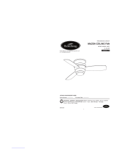
OPERATING INSTRUCTIONS
1. Restore electrical power to the outlet box by
turning the electricity on at the main fuse box.
ON
ON
ON
ON
ON
ON
ON
ON
2. Check the operation of the fan by gently
pulling on the fan chain coupler (EE).
1
st
Pull
2
nd
Pull
3
rd
Pull
4
th
Pull
High
Off
Low
Medium
Fan Pull Chain Operating Sequence
3. If airflow is desired in the opposite direction, turn
the fan off and wait for the blades to stop
turning. Slide the reverse switch to the opposite
position and turn fan on again.
Season
Summer
Winter
Rotation Direction Switch Position
Clockwise
Counterclockwise Right
Left
Reverse Switch Information
1
3
EE
2
15

BLADE BALANCING INSTRUCTIONS
Lowes.com/harborbreeze
I
FF
1
I
FF
2
I
FF
3
1. Interchanging positions of adjacent blades (I)
can redistribute the weight and result in
smoother operation. If wobble decreases,
leave blades (I) as they are. If wobble
increases, switch back to original position.
Attach the balancing clip from the balance kit
(FF) to the mid-point on the top edge of one
blade (I).
3. Peel the backing paper from one of the
weighted squares in the balance kit (FF).
Secure the weighted square in the balance kit
))¿UPO\WRWKHWRSRIWKHEODGH,
centered at the balancing clip location and
between the edges of the blade (I).
Remove the balancing clip (FF), start the fan
and observe. If the wobble still persists, repeat
steps 1 through 3 until the wobble disappears.
2. 5XQWKHIDQDWKLJKVSHHGDLUGRZQÀRZDQG
observe wobble. Repeat steps 1 and 2 for
each blade (I). Note which blade (I) has the
least wobble. On that blade (I), install the
balancing clip to the top edge of the blade (I)
near the blade arm (H).
Start the fan and observe wobble. Stop the fan
and move the balancing clip in small steps
toward the end of the blade (I). At each
incremental step, turn on the fan and observe
the wobble. Determine the location of the
balancing clip that gives the least amount of
wobble.
WARNING
7KHEDODQFLQJFOLSPXVWDOZD\VEH¿UPO\SXVKHG
onto the blade until it touches the edge of the
EODGH)DLOXUHWRGRVRFRXOGDOORZFOLSWRÀ\RII
and cause personal injury.
If the fan wobbles when in use, turn off the fan and follow the below steps:
16

TROUBLESHOOTING
When cleaning, use only a soft brush or lint-free cloth to avoid scratching the finish.
$EUDVLYHFOHDQLQJDJHQWVDUHQRWUHTXLUHGDQGVKRXOGEHDYRLGHGWRSUHYHQWGDPDJHWRILQLVK
RECOMMENDED: Periodically check that the fan motor unit screws, blade screws, support
housing and light kit screws are tight and secure.
3HULRGLFOLJKWGXVWLQJRIWKHEODGHVLVUHFRPPHQGHG$IHDWKHUGXVWHUZLOOZRUNEHVW
$YRLGXVLQJZDWHUFOHDQVHUVRUKDUVKUDJVZKLFKFDQZDUSDQGUXLQWKHILQLVK
Do not install or use fan if any part is damaged or missing.
CARE AND MAINTENANCE
4. Wire connectors inside housing are
rattling.
1. Blades not attached to fan.
2. Loose screws in motor housing.
3. Screws securing fan blade holders to
motor hub are loose.
Lowes.com/harborbreeze
WARNING
Do not use water when cleaning the ceiling fan. It could damage the motor or the finish and
create the possibility of electrical shock.
1. Check main and branch circuit
fuses or circuit breakers.
2. Check line wire connections to
fan and switch wire connections
in the switch housings.
WARNING
Make sure main power is turned
off!
WARNING
Make sure main power is turned
off!
4. Check to make sure wire
connectors in switch housing
are not rattling against each
other or against the interior wall
of the switch housing.
1. Attach blades to fan before
operating.
2. Check to make sure all screws
in motor housing are snug
(do not overtighten).
3. Check to make sure the screws
that attach the fan blade
holders to the motor hub are tight.
PROBLEM POSSIBLE CAUSE CORRECTIVE ACTION
Fan will not start. 1. Fuse or circuit breaker blown.
3. Reversing switch in neutral position. 3. Make sure reversing switch
position is all the way to one
side.
2. Loose power line connections to the
fan, or loose switch wire connections
in the switch housing assembly.
Fan sounds noisy.
17

TROUBLESHOOTING
Lowes.com/harborbreeze
5. Screws holding blades to blade
holders are loose.
5. Tighten screws securely. Fan sounds noisy.
Not enough air
movement.
6. Fan blades are out of balance.
1. Set screw in downrod support is loose.
2. Set screw in downrod/hanger ball
assembly is loose.
3. Screws securing fan blade holders to
motor hub are loose.
4. Blade holders are not seated properly.
5. Hanger bracket and/or ceiling outlet box
is not securely fastened.
If possible, consider using a longer
downrod (not included).
6. Interchanging position of fan
blades can redistribute the
weight and result in smoother
operation. For example,
exchange blades in positions 1
and 3 or 1 and 4. If this does
not improve wobble, exchange
2 and 4 or 2 and 5.
2. Tighten the set screw in the
downrod
/
han
g
er ball assembl
y.
3. Check to be sure screws that
attach the fan blade holders to the
motor hub are tight.
4. Check to be sure the fan blade
holders seat firmly and
uniformly to the surface of the
motor housing. If holders are
seated incorrectly, loosen the
screws and retighten.
5. Tighten the hanger bracket
screws to the outlet box, and
secure outlet box.
1. Tighten set screws securely in
downrod support.
Downrod is too short.
PROBLEM POSSIBLE CAUSE CORRECTIVE ACTION
Fan wobbles
excessively.
18

WARRANTY
To obtain warranty service, present a copy of your sales receipt as proof of purchase. All cost of
removal and reinstallation are the expressed responsibility of the purchaser. Any damage to the
ceiling fan by accident, misuse or improper installation, or by affixing accessories not produced by
this warranty, are at the purchaser’s own responsibility. The manufacturer assumes no responsibility
whatsoever for fan installation during the lifetime limited warranty. Any service performed by an
unauthorized person will render the warranty invalid.
Due to varying climate conditions, this warranty does not cover changes in brass finish, rusting,
pitting, tarnishing, corroding or peeling. Brass finish fans maintain their beauty when protected from
varying weather conditions. Any glass provided with this fan is not covered by the warranty.
Any replacement of defective parts for the ceiling fan must be reported within the first year from the
date of purchase. For the balance of the warranty, call our customer service department at
1-800-643-0067 for return authorization and shipping instructions so that we may repair or replace
the ceiling fan. Any fan or parts returned improperly packaged is the sole responsibility of the purchaser.
There is no further expressed warranty. The manufacturer disclaims any and all implied warranties.
The duration of any implied warranty which can not be disclaimed is limited to the lifetime limited
period as specified in our warranty. The manufacturer shall not be liable for incidental, consequential
or special damages arising at or in connection with product use or performance except as may
otherwise be accorded by law. This warranty gives you specific legal rights and you also have other
rights which vary from state to state. This warranty supersedes all prior warranties.
Note: A small amount of “wobble” is normal and should not be considered a defect.
Lowes.com/harborbreeze
The manufacturer warrants this fan to be free from defects in workmanship and material present at
time of shipment from the factory. The warranty terms from the date of purchase. The motor has a
lifetime warranty, and a 2 year warranty for the light kit and all remaining components. This warranty
applies only to the original purchaser. The manufacturer agrees to correct such defect at no charge
or, at our option, replace the ceiling fan with a comparable or superior model.
19

Printed in China
REPLACEMENT PARTS LIST
For replacement parts, call our customer service department at 1-800-643-0067, 8 a.m. - 6 p.m.,
EST, Monday - Thursday and 8 a.m. - 5 p.m., EST, Friday.
Lowes.com/harborbreeze
Harbor Breeze® is a registered
trademark of LF, LLC. All Rights
Reserved.
EE
DD
I
H
B
C
E
F
D
A
G
M
BB
CC
AA
FF
PART DESCRIPTION PART #
AMA8073LAZ
APGAC110RBL
ADRACT1-45LAZ
P801301LAZ
APPAC1101LAZ
AP1115LAZ
AP807301LAZ
AP807202LAZ
AP807203DB
HDWBH8072SS
HDWBM8072SS
HDWBM8072SS
HDWWNUTS4
ALP000002LAZ
LBALKT
Motor Assembly
Hanger Bracket
Downrod
Ceiling Canopy
Canopy Screw Cover
Motor Coupling Cover
Switch Housing
Assembly
Blade Arm
Blade
Screw
Washer-Head Screw
Fiber Washers
Wire Connector
Fan Chain Coupler
Balance Kit
A
B
C
D
E
F
G
H
I
AA
BB
CC
DD
EE
FF
20
/